FIELD OF THE INVENTION
The present invention generally relates to a die set with a guide sleeve having a seal, guide post and ball bearing assembly for maintaining the opposite die shoes of the die set in alignment during relative reciprocal movements.
BACKGROUND OF THE INVENTION
Bearing assemblies are well known. An example of a ball bearing assembly is disclosed in U.S. Pat. No. 4,664,534 dated May 12, 1987, and issued to the present inventor. The ball bearings within the ball bearing assembly must be lubricated to reduce the friction within the system to a minimum. The open ended guide sleeve of the U.S. Pat. No. 4,664,534 bearing assembly limits how and where the lubrication can be maintained in the system. Typically, the guide sleeve was maintained in a lower die shoe with a seal at the bottom thereby providing a reservoir for lubricating fluid, such as oil, to lubricate the ball bearings. In such a configuration, there were limitations on the amount of lubrication provided to the ball bearing cage. In the typical configuration, the lubricating fluid reservoir was only at the bottom of the guide sleeve. Therefore, the top portion of the ball bearing cage, which engages the guide post more often than the lower portion, did not receive optimal lubrication throughout its stroke.
Further, the open ended guide sleeve reservoir requires a spatial orientation including horizontal die shoes with the guide sleeve set vertically within the lower shoe. Any other orientation would result in the lubricating fluid leaking out of the reservoir, defeating the intended purpose and potentially interfering with the die casting, stamping or injection molding. Additionally, any debris or dirt in the system potentially could collect on the ball bearing assembly or the guide post thereby causing additional friction and wear leading to untimely loss of precision of the tooling and accuracy in the manufactured component.
Previously with guide post, guide sleeve and ball bearing assemblies there was not known any means for positively assuring an adequate lubrication of the ball bearing cage and maintaining a relatively dirt free environment for the ball bearings to act upon the guide post within the guide sleeve.
SUMMARY OF THE INVENTION
An important feature of the present invention is to provide adequate lubrication to the ball bearing cage assembly. The present invention maintains a superior lubricating system for the ball bearing assembly by having a sealing member fixedly attached to one end of the guide sleeve. The sealing member provides a means for maintaining a lubricating fluid reservoir within the entire guide sleeve that receives the entire ball bearing cage assembly inside an internal bore. The sealing member is placed between the interface between the guide sleeve and guide post providing a leak proof barrier to maintain lubricating fluid inside the guide sleeve. In this manner, the lubricating fluid is available to constantly lubricate the entire ball bearing cage.
An additional advantage of the inventive guide sleeve seal is that it effectively removes limits on the guide sleeve's spatial orientation relative to the die set. For example, previously guide sleeves had to be placed vertically within a lower horizontal die shoe so that any lubricating fluid maintained in a reservoir at the bottom of the guide sleeve would not leak out during a typical die casting operation. With the inventive sealing member attached to a guide sleeve, it is possible to maintain a guide sleeve on an upper horizontal die shoe or a vertical die shoe or one oriented at any angle. In this manner, greater versatility is available for configuring die sets allowing full lubrication of the ball bearing cage without allowing any of the lubricating fluid to leak into the system outside of the guide sleeve. Moreover, affixing the guide sleeve to an upper die shoe concentrates the lubricating fluid where it is needed most; at the points where the ball bearing assembly engages the guide post throughout a die casting operation.
A further advantage of the present invention is that it provides a means for cleaning the guide post during a die casting, metal stamping or injection molding operation. The sealing member travels longitudinally along the surface of the guide post during the die shoe reciprocal movements effectively cleaning the guide post. The seal provides a sweeping, cleaning action as it slides along the guide post. In this manner, any debris or dirt that collects on the guide post during a die casting operation is pushed away by the sealing member preventing it from entering the guide sleeve, collecting on the ball bearings or contaminating the lubricating fluid. Therefore, the inventive guide sleeve seal provides a means for maintaining cleaner lubrication of the ball bearing cage assembly which, effectively reduces the amount of friction between the guide post, guide sleeve, and the interposed ball bearings and lengthens life of original tooling specification.
These and other features and objects of the present invention will be seen in the following specification and claims in conjunction with the appended drawings, of which the following is a brief description.
BRIEF DESCRIPTION OF THE DRAWINGS
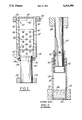
FIG. 1 is a partial cross sectional view of the inventive guide sleeve, guide post and ball bearing assembly interposed between upper and lower die shoes of a die set.
FIG. 2 is a partial cross sectional view of a prior art guide sleeve, guide post and ball bearing assembly showing an open ended guide sleeve.
DETAILED DESCRIPTION OF THE INVENTION
Referring to FIG. 1, there is shown a guide sleeve, guide post and ball bearing assembly incorporating the inventive guide sleeve sealing member. The guide post 20 is shown affixed to a lower die shoe 22 press fitted in an inner aperture 24 in the lower die shoe.
Guide sleeve 26 is shown affixed to an upper die shoe 28 within an aperture 30 and axially aligned such that it slidably receives guide post 20 during relative reciprocal movements between die shoes 22 and 28. Guide sleeve 26 has an internal coaxial bore 32 and a plug 34 maintained at the end of the guide sleeve affixed to the die shoe 28. At the opposite end of the guide sleeve, there is a sealing member 36 which slidably seals the interface between the free end 37 of guide sleeve 26 and guide post 20.
Sealing member 36 is fixedly maintained within the free end 37 of guide sleeve 26. Free end 37 preferably has a tapered, conical exterior that is narrowest near a terminal point on guide sleeve 26. The interior of free end 37 is preferably of a smaller radius than interior bore 32. The inner peripheral surface of free end 37 preferably has a nominal radius that is only slightly larger than the outside radius of guide post 20 such that guide sleeve 26 slidably receives guide post 20. Free end 37 preferably contains a notch 38 extending radially outward and having a radius that is slightly larger than the nominal radius of free end 37. Notch 38 preferably has a constant radius for a portion of its longitudinal length beginning at a reaction surface 39a defined at a most internal end of the notch and ending at a second reaction surface 39b. The radial length of the second, more external reaction surface 39b is approximately half the length of the most internal reaction surface 39a, which is equal to the radius of the notch at its most internal end minus the nominal radius of free end 37. Adjacent the second reaction surface, the radius of notch 38 begins to steadily decrease until a point adjacent a terminal point on guide sleeve 26 where the radius of notch 38 is approximately equal to the nominal radius of free end 37. Notch 38, therefore has a tapered conical portion that is widest at its most internal end and extends longitudinally outward from second reaction surface 39b to a point adjacent a terminal point on guide sleeve 26.
The shape of notch 38, therefore, defines a pair of axially opposing reaction surfaces 39a and 39b that bear against sealing member 36 such that sealing member 36 remains stationary relative to guide sleeve 26 during reciprocal movements between guide sleeve 26 and guide post 20. In this manner, free end 37 of guide sleeve 26 is shaped to securely contain a sealing means 36 such as a correspondingly shaped rubber coaxial ring.
The ball bearing cage 40 is of cylindrical form and is maintained within the central bore 32 of the guide sleeve and adjustably receives the guide post 20. Cage 40 is maintained in central bore 32 by known retention means, such as for example the retention means disclosed in U.S. Pat. No. 4,665,534 which is incorporated herein by reference. Ball bearing cage 40 maintains a plurality of ball bearings 42 in a series of longitudinally spaced circles of radially bored holes. The ball bearings 42 are circularly arranged and project inwardly and outwardly respectively, of the ball bearing cage 40 and are engageable with guide post 20 and with the internal coaxial bore 32 of guide sleeve 26.
A reservoir 43 for lubricating fluid 44 is maintained within internal bore 32 between the end 45 of the interior of the guide sleeve 26 and the plug 34 by seal 36. In the disclosed embodiment, oil is supplied to the interior of guide sleeve 26 through openings 50 in sleeve 26. Lube filler openings 52 are provided in the die shoe 28 and intersect the opening 50. Therefore, the ball bearing cage 40 is maintained within a generally enclosed environment containing lubricating fluid. Moreover, the inventive configuration allows for the lubricating fluid to be maintained where it is required most. In the illustrated embodiment, the ball bearing cage 40 engages the guide post 20 near the lower end of the guide sleeve. With the inventive guide sleeve seal configuration, it is possible to concentrate lubricating fluid at the lower end of the guide sleeve thereby lubricating the ball bearings at the point where they engage the guide post throughout its stroke which may reach 2500 strokes per minute. The inventive configuration facilitates cooler operation under such high speed conditions, and therefore, adds additional life to original tolerance specifications.
Although FIG. 1 illustrates guide sleeve 26 above guide post 20, the configuration could be reversed such that guide sleeve 26 is below guide post 20. In this latter configuration, sleeve 26 is preferably modified to include a cap to prevent lubrication loss or migration.
FIG. 2, wherein like numerals refer to like parts of the guide post, guide sleeve assemblies, shows an example of the prior art wherein the oil reservoir 46 is maintained at a lowest end of the guide sleeve closest to the die shoe 22 and furthest from the point where the ball bearing cage assembly adjustably receives the guide post. Therefore, optimal lubrication of the ball bearings is not maintained without the inventive guide sleeve seal configuration.
Referring again now to FIG. 1, as guide post 20 and guide sleeve 26 move reciprocally, the sealing member 36 slidingly moves longitudinally along guide post 20 effectively performing a cleaning action along the edge of the guide post. Therefore, sealing member 36 prevents any dirt, dust or debris which may have collected on guide post 20 from entering into the lubricating fluid reservoir 43. As can be seen in FIG. 2, in the prior art, a gap exists between guide sleeve 26 and guide post 20 such that any debris or dirt collecting on guide post 20 could contaminate the lubricating fluid 48. Therefore, the inventive guide sleeve seal provides a more effective lubricating fluid reservoir, resulting in a better, more frictionless environment within a die set. In the prior art, any debris or dirt collecting on a ball bearing or guide post or within the lubricating fluid reservoir would increase the amount of friction during reciprocal movement of the guide post and guide sleeve with the interposed bill bearing cage assembly and could scar the post creating more wear on the system.
The inventive guide sleeve seal is adaptable for use with any guide sleeve, guide post and ball bearing assembly for a die set including those where the ball bearing assembly is not rotatably mounted and those where the ball bearing assembly is rotatably mounted, such as in U.S. Pat. No. 4,664,534, previously described.
It will be apparent to those skilled in the art that the foregoing disclosure is exemplary in nature rather than limiting, the invention being limited only by the appended claims.