US5311715A - Expansion joint flexible seal - Google Patents

Expansion joint flexible seal Download PDF

Info

Publication number
US5311715A
US5311715A US07/598,250 US59825090A US5311715A US 5311715 A US5311715 A US 5311715A US 59825090 A US59825090 A US 59825090A US 5311715 A US5311715 A US 5311715A
Authority
US
United States
Prior art keywords
filter element
insulating body
pair
flexible
end faces
Prior art date
Legal status (The legal status is an assumption and is not a legal conclusion. Google has not performed a legal analysis and makes no representation as to the accuracy of the status listed.)
Expired - Fee Related
Application number
US07/598,250
Inventor
Ed Linck
Neil R. Raskin
V. Swaminathan
Current Assignee (The listed assignees may be inaccurate. Google has not performed a legal analysis and makes no representation or warranty as to the accuracy of the list.)
AHLSTROM PYROPOWER Inc A CORP OF
PYROPOWER Corp A NY CORP
Pyropower Corp
Original Assignee
Pyropower Corp
Priority date (The priority date is an assumption and is not a legal conclusion. Google has not performed a legal analysis and makes no representation as to the accuracy of the date listed.)
Filing date
Publication date
Application filed by Pyropower Corp filed Critical Pyropower Corp
Priority to US07/598,250 priority Critical patent/US5311715A/en
Priority to US07/773,217 priority patent/US5383316A/en
Assigned to AHLSTROM PYROPOWER, INC., A CORP. OF CA reassignment AHLSTROM PYROPOWER, INC., A CORP. OF CA ASSIGNMENT OF ASSIGNORS INTEREST. Assignors: LINCK, ED, RASKIN, NEIL R., SWAMINATHAN, V.
Assigned to PYROPOWER CORPORATION reassignment PYROPOWER CORPORATION ASSIGNMENT OF ASSIGNORS INTEREST (SEE DOCUMENT FOR DETAILS). Assignors: LINCK, ED, SWAMINATHAN, V., RASKIN, R.
Priority to US08/118,389 priority patent/US5560166A/en
Assigned to PYROPOWER CORPORATION, A NY CORP. reassignment PYROPOWER CORPORATION, A NY CORP. REQUEST FOR CORRECTION OF RECORDED ASSIGNMENT DOCUMENT PREVIOUSLY RECORDED AT REEL 6587, FRAME NOS. 0104-0109. Assignors: LINCK, ED, SWAMINATHAN, V., RASKIN, NEAL R.
Application granted granted Critical
Publication of US5311715A publication Critical patent/US5311715A/en
Anticipated expiration legal-status Critical
Expired - Fee Related legal-status Critical Current

Links

Images

Classifications

    • FMECHANICAL ENGINEERING; LIGHTING; HEATING; WEAPONS; BLASTING
    • F16ENGINEERING ELEMENTS AND UNITS; GENERAL MEASURES FOR PRODUCING AND MAINTAINING EFFECTIVE FUNCTIONING OF MACHINES OR INSTALLATIONS; THERMAL INSULATION IN GENERAL
    • F16LPIPES; JOINTS OR FITTINGS FOR PIPES; SUPPORTS FOR PIPES, CABLES OR PROTECTIVE TUBING; MEANS FOR THERMAL INSULATION IN GENERAL
    • F16L51/00Expansion-compensation arrangements for pipe-lines
    • F16L51/02Expansion-compensation arrangements for pipe-lines making use of bellows or an expansible folded or corrugated tube
    • F16L51/024Expansion-compensation arrangements for pipe-lines making use of bellows or an expansible folded or corrugated tube non-metallic
    • FMECHANICAL ENGINEERING; LIGHTING; HEATING; WEAPONS; BLASTING
    • F16ENGINEERING ELEMENTS AND UNITS; GENERAL MEASURES FOR PRODUCING AND MAINTAINING EFFECTIVE FUNCTIONING OF MACHINES OR INSTALLATIONS; THERMAL INSULATION IN GENERAL
    • F16JPISTONS; CYLINDERS; SEALINGS
    • F16J15/00Sealings
    • F16J15/02Sealings between relatively-stationary surfaces
    • F16J15/06Sealings between relatively-stationary surfaces with solid packing compressed between sealing surfaces
    • F16J15/064Sealings between relatively-stationary surfaces with solid packing compressed between sealing surfaces the packing combining the sealing function with other functions
    • F16J15/065Sealings between relatively-stationary surfaces with solid packing compressed between sealing surfaces the packing combining the sealing function with other functions fire resistant
    • FMECHANICAL ENGINEERING; LIGHTING; HEATING; WEAPONS; BLASTING
    • F16ENGINEERING ELEMENTS AND UNITS; GENERAL MEASURES FOR PRODUCING AND MAINTAINING EFFECTIVE FUNCTIONING OF MACHINES OR INSTALLATIONS; THERMAL INSULATION IN GENERAL
    • F16LPIPES; JOINTS OR FITTINGS FOR PIPES; SUPPORTS FOR PIPES, CABLES OR PROTECTIVE TUBING; MEANS FOR THERMAL INSULATION IN GENERAL
    • F16L59/00Thermal insulation in general
    • F16L59/14Arrangements for the insulation of pipes or pipe systems
    • F16L59/16Arrangements specially adapted to local requirements at flanges, junctions, valves or the like
    • F16L59/21Arrangements specially adapted to local requirements at flanges, junctions, valves or the like adapted for expansion-compensation devices
    • FMECHANICAL ENGINEERING; LIGHTING; HEATING; WEAPONS; BLASTING
    • F23COMBUSTION APPARATUS; COMBUSTION PROCESSES
    • F23JREMOVAL OR TREATMENT OF COMBUSTION PRODUCTS OR COMBUSTION RESIDUES; FLUES 
    • F23J13/00Fittings for chimneys or flues 
    • F23J13/04Joints; Connections
    • FMECHANICAL ENGINEERING; LIGHTING; HEATING; WEAPONS; BLASTING
    • F23COMBUSTION APPARATUS; COMBUSTION PROCESSES
    • F23JREMOVAL OR TREATMENT OF COMBUSTION PRODUCTS OR COMBUSTION RESIDUES; FLUES 
    • F23J2213/00Chimneys or flues
    • F23J2213/20Joints; Connections
    • F23J2213/202Joints; Connections between duct or stack sections

Definitions

  • the field of the present invention is expansion joints for ducting and flue systems, and more particularly, nonmetallic flexible expansion joints to provide stress relief in refactory lined flue systems used in high temperature applications such as power generation and related activities.
  • FIG. 1 illustrates a power generation plant of unique design that includes a furnace having a circulating fluidized bed (CFB) wherein various fuel materials are combusted.
  • the hot flue gases containing combustion by-products are transferred from the furnace through a flue/expansion joint to a cyclone separator.
  • the cyclone separator diverts heavier combustion particulate matter back to the CFB and the fine particulate matter and hot flue gases are directed through a heat exchanger.
  • the fine particulate matter is then diverted to a particulate filter for disposal.
  • Gases emitted from the facility will have most of the combustion by-product emissions, including NO x , SO 2 , CO, particulates, etc., removed therefrom, resulting in an environmentally safe means of power generation.
  • Nonmetallic flue expansion joints are flexible connectors designed to provide stress relief in flue systems by absorbing movement caused by thermal changes. They also act as vibration isolators, and in some instances, make up for minor misalignment of adjoining flues or equipment. They may be fabricated from a wide variety of nonmetallic materials, including synthetic elastomers, fabrics, insulation materials and other suitable materials depending upon the designs thereof. Since their introduction in the early 1960's, the use of nonmetallic expansion joints has continuously grown. The advent of more rigid emission standards has caused the use of more complex flue work systems. Nonmetallic expansion joints have been used in place of the traditional all metal expansion joints to solve problems caused by the thermal and mechanical stresses generated in these complex systems.
  • FIG. 2 A typical prior art nonmetallic expansion joint is shown in FIG. 2.
  • the joint includes a pair of angle brackets mounted to the respective ends of a pair of adjoining ducts or flues.
  • a pair of frame members are in turn attached to the angle brackets.
  • the frame members have mounted thereto a flexible pressure seal that extends around the periphery of the expansion joint.
  • the pressure seal may be of the elastomeric type for operation below 400 degrees F or may be of the composite type for operation at temperatures continuously above 400 degrees F. It will be appreciated that the flexible pressure seal allows relative axial, transverse, angular and rotational movement between the respective ducts while preventing the escape of pressurized flue gasses and particulates carried therein.
  • nonmetallic expansion joints are prone to failure from the build-up of abrasive particulates carried by the flue gas stream, which can accumulate in the expansion joint in such quantities that they eventually rupture the pressure seal.
  • fly ash and other particulates can cause damage to the expansion joint by solidifying to a cementatious state.
  • certain non-cementatious particulates can create a severe, corrosive (acidic) environment when subjected to cooling (below the H 2 SO 4 dew point) during a maintenance outage.
  • baffles have been proposed to help direct particulate matter beyond the expansion joint, as shown in FIG. 2.
  • Other proposals include mounting the flexible pressure seal substantially flush with the interior surface of the duct or flue, as shown in FIG. 3, or mounting an insulation barrier behind a baffle arrangement as shown in FIG. 4.
  • FIG. 3 may result in thermal transfer on the inner face of the expansion joint and abrasion from particulates in the gas stream. A greater setback would be desirable.
  • the arrangement of FIG. 4 may result in the insulation barrier rubbing on the baffle under negative pressures.
  • the insulation barrier must be fixedly attached to both sides of the joint, which may complicate joint construction and also impart adverse loads on the barrier.
  • the present invention accomplishes the foregoing objects and advantages. It is therefore an object of the present invention to provide an improved expansion joint and flexible seal therefor.
  • an expansion joint may include flexible seal means having flexible insulating body means and filter means positioned adjacent thereto. Additional filter element means may be provided, as well as flexible seal mounting means for easy installation and joint accessibility.
  • FIG. 1 is a diagrammatic view of a fluidized circulating bed power generation plant that includes expansion joints in the ducting system thereof;
  • FIG. 2 is a detailed cross-sectional view of a prior art expansion joint having a baffle system to prevent premature joint failure;
  • FIG. 3 is a detailed cross-sectional view of another prior art expansion joint having a flush mounted flexible pressure seal also designed to eliminate premature joint failure;
  • FIG. 4 is a detailed cross-sectional view of still another prior art expansion joint having an insulation barrier and baffle system also designed to minimize premature joint failure;
  • FIG. 5 is a detailed cross-sectional view of a nonmetallic expansion joint and flexible seal constructed in accordance with the present invention.
  • FIG. 6 is a detailed isometric view of a flexible seal constructed in accordance with the present invention having a portion broken away for clarity;
  • FIG. 7 is a plan view of the flexible seal of FIG. 6 having end portions adapted for interlocking with adjacent flexible seal elements;
  • FIG. 8 is an exploded detailed cross-sectional view of a nonmetallic expansion joint and flexible seal constructed in accordance with the present invention.
  • the invention may be embodied in structural form in a nonmetallic expansion joint 2 provided between a pair of refractory lined flues 4 and 6.
  • the flues 4 and 6 include respective refractory portions 8 and 10 and metallic outer shell portions 12 and 14, respectively.
  • the flue sections 4 and 6 terminate at respective terminal faces 16 and 18 which are positioned to form a gap extending around the periphery of the duct sections.
  • a pressure seal assembly including a flexible pressure seal 20 fastened in conventional fashion to a pair of angle frames 22 and 24 which are in turn mounted to a pair of angle brackets 26 and 28 that are permanently attached by welding or other means to the metallic shell portions 12 and 14 of the flues 4 and 6.
  • a flexible seal assembly 30 Disposed in the gap formed by the terminal flue faces 16 and 18 is a flexible seal assembly 30, the details of which will now be described.
  • the flexible seal assembly 30 includes a flexible insulating body 32 made from a ceramic fiber blanket material of suitable density, such as blown or spun alumina silicate material, and a pair of insulating side panels 34 and 36 also made from a ceramic fiber board material of suitable density providing a pair of lateral or side faces adapted for positioning adjacent and parallel to the respective terminal flue faces 16 and 18.
  • the flexible insulating body 32 further includes a pair of end faces 38 and 40 adapted to be positioned generally perpendicularly to the terminal flue faces 16 and 18.
  • the insulating body further includes a longitudinal dimension extending in a direction shown by the arrow A, so as to generally extend along the perimeter of the flue elements 4 and 6.
  • the flexible seal 30 further includes a pair of filter elements 50 and 52 positioned adjacent to the respective end faces 38 and 40 and extending in the longitudinal direction of the insulating body.
  • the filter elements are preferably formed from a wire mesh material arranged in a plurality of wrapping arrangements.
  • a suitable wire mesh material such as 304 SS wire mesh may be rolled into a series of tubes 54 and 56.
  • a plurality of the tubes 54 may be arranged in a bundle, with one of the tubes 54 serving as a central core tube, and wrapped in a larger wire mesh wrapping 58 to complete the filter element 50.
  • the filter element 52 can be formed by a plurality of wire mesh tube elements 56 arranged around a central core tube to form a tube bundle, with the bundle being wrapped in a larger wire mesh wrapping 60 to form the filter element 52.
  • the filter elements 50 and 52 could be formed from a pair of solid core flexible hoses. Other filter constructions could also be employed.
  • Means are provided for securing the filter elements 50 and 52 to the insulating body 32 in the form of a wire mesh wrapping 70 that extends around the filter elements and the insulating body.
  • the wire mesh wrapping may also be 304SS wire mesh.
  • the assembly 30 may be further secured in an exterior flexible casing or wrapping 80 formed from high temperature plastic, or other material.
  • Other wrapping configurations would also no doubt be possible.
  • there may be provided a thin (e.g. one-sixteenth inch) ceramic fiber paper covering under the exterior wrapping 80.
  • the flexible seal assembly 30 may further be secured with a wire mesh cloth 90 extending between the filter elements 50 and 52, through the insulating core 32.
  • a wire mesh cloth 90 extending between the filter elements 50 and 52, through the insulating core 32.
  • the transverse tie wires 100 may be anchored in the external wire mesh wrapping 70.
  • the flexible seal assembly 30 includes end portions 110 and 112 having respective cut-outs 114 and 116 formed therein to provide for interlocking arrangement of successive seal assemblies disposed around the periphery of the flues 4 and 6.
  • the modular seal assembles 30 may be easily joined in forming the expansion joint tube by initially mounting the seal assemblies on pin members 120 extending from the terminal face 16 of the flue 4 attached to the flue 4. Once the seal assemblies 30 are arranged around the periphery of the flue 4 on the pins 120, the adjoining flue section 6 may be applied into place against the seal assemblies 30 until the seal assemblies are moderately compressed. The external pressure seal may then be attached to the angle frame members 22 and 24 to complete the seal. Alternatively, additional insulative material 130 may be placed between the angle brackets 26 and 28 and the pressure seal 20 attached thereafter. The insulative material 130 will provide an additional insulative barrier between the hot duct flue gases and the external pressure seal.

Landscapes

  • Engineering & Computer Science (AREA)
  • General Engineering & Computer Science (AREA)
  • Mechanical Engineering (AREA)
  • Gasket Seals (AREA)

Abstract

An expansion joint and flexible seal for refractory lined flues includes a flexible insulating body having a pair of end faces, a pair of lateral faces and a longitudinal dimension. The flexible seal further includes a filter element positioned adjacent to one of the end faces and extending in the longitudinal dimension. The filter element is attached to the insulating body and the assembly may be placed with other seal assemblies in endwise fashion around the periphery of a pair of opposing flue members. A further external pressure seal is provided, mounted to each end of the flue elements.

Description

BACKGROUND OF THE INVENTION
The field of the present invention is expansion joints for ducting and flue systems, and more particularly, nonmetallic flexible expansion joints to provide stress relief in refactory lined flue systems used in high temperature applications such as power generation and related activities.
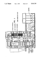
In power generating or cogeneration plants, including facilities for obtaining usable electrical power or processing steam/hot water from the burning of solid, liquid or gaseous fuel products, hot flue gases generated by the combustion process are typically directed through a series of processing areas to remove particulates and environmentally hazardous components before finally being exhausted from the facility. FIG. 1 illustrates a power generation plant of unique design that includes a furnace having a circulating fluidized bed (CFB) wherein various fuel materials are combusted. The hot flue gases containing combustion by-products are transferred from the furnace through a flue/expansion joint to a cyclone separator. The cyclone separator diverts heavier combustion particulate matter back to the CFB and the fine particulate matter and hot flue gases are directed through a heat exchanger. The fine particulate matter is then diverted to a particulate filter for disposal. Gases emitted from the facility will have most of the combustion by-product emissions, including NOx, SO2, CO, particulates, etc., removed therefrom, resulting in an environmentally safe means of power generation.
Nonmetallic flue expansion joints are flexible connectors designed to provide stress relief in flue systems by absorbing movement caused by thermal changes. They also act as vibration isolators, and in some instances, make up for minor misalignment of adjoining flues or equipment. They may be fabricated from a wide variety of nonmetallic materials, including synthetic elastomers, fabrics, insulation materials and other suitable materials depending upon the designs thereof. Since their introduction in the early 1960's, the use of nonmetallic expansion joints has continuously grown. The advent of more rigid emission standards has caused the use of more complex flue work systems. Nonmetallic expansion joints have been used in place of the traditional all metal expansion joints to solve problems caused by the thermal and mechanical stresses generated in these complex systems. Although the major user of the nonmetallic joint continues to be the power generation industry, the use of this product has expanded into many other industries wherein gases are conveyed including pulp and paper plants, refineries, steel mills, foundries, smelters, cement plants, kilns, refuse incineration, marine applications, vapor-heat-dust recovery, food processing, and HVAC (Heating, Ventilating and Air Conditioning).
A typical prior art nonmetallic expansion joint is shown in FIG. 2. The joint includes a pair of angle brackets mounted to the respective ends of a pair of adjoining ducts or flues. A pair of frame members are in turn attached to the angle brackets. The frame members have mounted thereto a flexible pressure seal that extends around the periphery of the expansion joint. The pressure seal may be of the elastomeric type for operation below 400 degrees F or may be of the composite type for operation at temperatures continuously above 400 degrees F. It will be appreciated that the flexible pressure seal allows relative axial, transverse, angular and rotational movement between the respective ducts while preventing the escape of pressurized flue gasses and particulates carried therein. Other nonmetallic expansion joint constructions may be seen in the "Technical Handbook" published by the Ducting Systems Nonmetallic Expansion Joint Division of the Fluid Sealing Association, 2017 Walnut Street, Philadelphia, Pa. 19103 (2nd Edition), the contents of which are fully incorporated herein by this reference.
It is known that nonmetallic expansion joints are prone to failure from the build-up of abrasive particulates carried by the flue gas stream, which can accumulate in the expansion joint in such quantities that they eventually rupture the pressure seal. Moreover, fly ash and other particulates can cause damage to the expansion joint by solidifying to a cementatious state. Also, certain non-cementatious particulates (fly ash) can create a severe, corrosive (acidic) environment when subjected to cooling (below the H2 SO4 dew point) during a maintenance outage.
To prevent premature expansion joint failure from the build up of particulate matter therein, baffles have been proposed to help direct particulate matter beyond the expansion joint, as shown in FIG. 2. Other proposals include mounting the flexible pressure seal substantially flush with the interior surface of the duct or flue, as shown in FIG. 3, or mounting an insulation barrier behind a baffle arrangement as shown in FIG. 4. Although these proposals may exhibit varying degrees of effectiveness in minimizing expansion joint failure, the arrangement of FIG. 3 may result in thermal transfer on the inner face of the expansion joint and abrasion from particulates in the gas stream. A greater setback would be desirable. The arrangement of FIG. 4 may result in the insulation barrier rubbing on the baffle under negative pressures. Moreover, the insulation barrier must be fixedly attached to both sides of the joint, which may complicate joint construction and also impart adverse loads on the barrier.
Accordingly, there is an evident need for an expansion joint flexible seal which not only prevents particulate build up, but which is durable, easy to install and will perform satisfactorily despite joint movement. It would be further desirable to provide an expansion joint flexible seal that also performs a sealing function to provide an additional gas sealing barrier.
The present invention accomplishes the foregoing objects and advantages. It is therefore an object of the present invention to provide an improved expansion joint and flexible seal therefor.
It is a further object of the present invention to provide an expansion joint having a flexible seal that is not adversely affected by relative joint movement.
It is a further object of the present invention to provide an expansion joint having a modular construction for easier installation.
It is a further object of the present invention to provide an expansion joint and flexible seal therefor providing an additional gas sealing barrier.
SUMMARY OF THE INVENTION
The present invention employs concepts for an expansion joint and flexible seal therefor that accomplish the foregoing objects and advantages. In accordance therewith, an expansion joint may include flexible seal means having flexible insulating body means and filter means positioned adjacent thereto. Additional filter element means may be provided, as well as flexible seal mounting means for easy installation and joint accessibility.
BRIEF DESCRIPTION OF THE DRAWINGS
The objects, advantages and features of this invention will be more clearly perceived from the following detailed description when read in accordance with the accompanying drawing in which:
FIG. 1 is a diagrammatic view of a fluidized circulating bed power generation plant that includes expansion joints in the ducting system thereof;
FIG. 2 is a detailed cross-sectional view of a prior art expansion joint having a baffle system to prevent premature joint failure;
FIG. 3 is a detailed cross-sectional view of another prior art expansion joint having a flush mounted flexible pressure seal also designed to eliminate premature joint failure;
FIG. 4 is a detailed cross-sectional view of still another prior art expansion joint having an insulation barrier and baffle system also designed to minimize premature joint failure;
FIG. 5 is a detailed cross-sectional view of a nonmetallic expansion joint and flexible seal constructed in accordance with the present invention;
FIG. 6 is a detailed isometric view of a flexible seal constructed in accordance with the present invention having a portion broken away for clarity;
FIG. 7 is a plan view of the flexible seal of FIG. 6 having end portions adapted for interlocking with adjacent flexible seal elements; and
FIG. 8 is an exploded detailed cross-sectional view of a nonmetallic expansion joint and flexible seal constructed in accordance with the present invention.
DETAILED DESCRIPTION OF PREFERRED EMBODIMENTS
Referring now to FIG. 5, the invention may be embodied in structural form in a nonmetallic expansion joint 2 provided between a pair of refractory lined flues 4 and 6. The flues 4 and 6 include respective refractory portions 8 and 10 and metallic outer shell portions 12 and 14, respectively. The flue sections 4 and 6 terminate at respective terminal faces 16 and 18 which are positioned to form a gap extending around the periphery of the duct sections. There is also conventionally provided a pressure seal assembly including a flexible pressure seal 20 fastened in conventional fashion to a pair of angle frames 22 and 24 which are in turn mounted to a pair of angle brackets 26 and 28 that are permanently attached by welding or other means to the metallic shell portions 12 and 14 of the flues 4 and 6. Disposed in the gap formed by the terminal flue faces 16 and 18 is a flexible seal assembly 30, the details of which will now be described.
Turning now to FIG. 6, the flexible seal assembly 30 includes a flexible insulating body 32 made from a ceramic fiber blanket material of suitable density, such as blown or spun alumina silicate material, and a pair of insulating side panels 34 and 36 also made from a ceramic fiber board material of suitable density providing a pair of lateral or side faces adapted for positioning adjacent and parallel to the respective terminal flue faces 16 and 18. The flexible insulating body 32 further includes a pair of end faces 38 and 40 adapted to be positioned generally perpendicularly to the terminal flue faces 16 and 18. The insulating body further includes a longitudinal dimension extending in a direction shown by the arrow A, so as to generally extend along the perimeter of the flue elements 4 and 6.
The flexible seal 30 further includes a pair of filter elements 50 and 52 positioned adjacent to the respective end faces 38 and 40 and extending in the longitudinal direction of the insulating body. The filter elements are preferably formed from a wire mesh material arranged in a plurality of wrapping arrangements. Thus, a suitable wire mesh material such as 304 SS wire mesh may be rolled into a series of tubes 54 and 56. To form the filter element 50, a plurality of the tubes 54 may be arranged in a bundle, with one of the tubes 54 serving as a central core tube, and wrapped in a larger wire mesh wrapping 58 to complete the filter element 50. Similarly, the filter element 52 can be formed by a plurality of wire mesh tube elements 56 arranged around a central core tube to form a tube bundle, with the bundle being wrapped in a larger wire mesh wrapping 60 to form the filter element 52. Alternatively, the filter elements 50 and 52 could be formed from a pair of solid core flexible hoses. Other filter constructions could also be employed.
Means are provided for securing the filter elements 50 and 52 to the insulating body 32 in the form of a wire mesh wrapping 70 that extends around the filter elements and the insulating body. The wire mesh wrapping may also be 304SS wire mesh. The assembly 30 may be further secured in an exterior flexible casing or wrapping 80 formed from high temperature plastic, or other material. Other wrapping configurations would also no doubt be possible. For example, there may be provided a thin (e.g. one-sixteenth inch) ceramic fiber paper covering under the exterior wrapping 80.
The flexible seal assembly 30 may further be secured with a wire mesh cloth 90 extending between the filter elements 50 and 52, through the insulating core 32. There may be also provided a pair of transverse tie-wires 100 extending through the insulating core 32 and side panels 34 and 36. The transverse tie wires 100 may be anchored in the external wire mesh wrapping 70.
Turning now to FIG. 7, the flexible seal assembly 30 includes end portions 110 and 112 having respective cut- outs 114 and 116 formed therein to provide for interlocking arrangement of successive seal assemblies disposed around the periphery of the flues 4 and 6.
As further shown in FIG. 8, the modular seal assembles 30 may be easily joined in forming the expansion joint tube by initially mounting the seal assemblies on pin members 120 extending from the terminal face 16 of the flue 4 attached to the flue 4. Once the seal assemblies 30 are arranged around the periphery of the flue 4 on the pins 120, the adjoining flue section 6 may be applied into place against the seal assemblies 30 until the seal assemblies are moderately compressed. The external pressure seal may then be attached to the angle frame members 22 and 24 to complete the seal. Alternatively, additional insulative material 130 may be placed between the angle brackets 26 and 28 and the pressure seal 20 attached thereafter. The insulative material 130 will provide an additional insulative barrier between the hot duct flue gases and the external pressure seal.
It is understood that the foregoing description and accompanying illustrations are merely exemplary and are in no way intended to limit the scope of the invention. Various changes and modifications to the preferred embodiments should be apparent to those skilled in the art. Such changes and modifications could be made without departing from the spirit and scope of the invention. Accordingly, it is intended that all such changed and modifications be covered by the appended claims and equivalents.

Claims (15)

What is claimed is:
1. A flue and duct system expansion joint flexible seal comprising:
a flexible insulating body having a pair of end faces, a pair of lateral faces and a longitudinal dimension;
a filter element positioned adjacent one of said end faces and extending in said longitudinal dimension, said filter element being made from a wire mesh material; and
means for securing said filter element to said insulating body.
2. A flue and duct system expansion joint flexible seal comprising:
a flexible insulating body having a pair of end faces, a pair of lateral faces and a longitudinal dimension;
a filter element positioned adjacent one of said end faces and extending in said longitudinal dimension, said filter element including a wrapping of wire mesh cloth; and
means for securing said filter element to said simulating body.
3. A flue and duct system expansion joint flexible seal comprising:
a flexible insulating body having a pair of end faces, a pair of lateral faces and a longitudinal dimension;
a filter element positioned adjacent one of said end faces and extending in said longitudinal dimension, said filter element including a plurality of wire mesh elements wrapped in a larger wire mesh wrapping; and
means for securing said filter element to said insulating body.
4. A flue and duct system expansion joint flexible seal comprising:
a flexible insulating body having a pair of end faces, a pair of lateral faces and a longitudinal dimension;
a filter element positioned adjacent one of said end faces and extending in said longitudinal dimension; and
means for securing said filter element to said insulating body including a wire mesh wrapping around said filter element and said insulating body.
5. The flexible seal of claim 4 wherein said means for securing said filter element to said insulating body further includes a flexible casing that encases said wire mesh wrapping.
6. A flue and duct system expansion joint flexible seal comprising:
a flexible insulating body having a pair of end faces, a pair of lateral faces, and a longitudinal dimension;
a filter element positioned adjacent one of said end faces and extending in said longitudinal dimension, said filter element including a pair of filter elements positioned on said end faces; and
means for securing said filter elements to said insulating body including a tie fastened to said filter elements and extending through said insulating body.
7. A flue and duct system expansion joint flexible seal comprising:
a flexible insulating body having a pair of end faces, a pair of lateral faces and a longitudinal dimension, said insulating body including a central insulating core and a pair of simulating side panels providing said lateral faces;
a filter element positioned adjacent one of said end faces and extending in said longitudinal dimension, said filter element including a wrapping of wire cloth; and
means for securing said filter element to said insulating body.
8. The flexible seal of claim 7 wherein said filter element includes a plurality of wire mesh elements wrapped in a larger wire mesh wrapping.
9. The flexible seal of claim 8 wherein said means for securing said filter element to said insulating body includes a wire mesh wrapping around said filter element and said insulating body.
10. The flexible seal of claim 9 wherein said means for securing said filter element to said insulating body further includes a flexible casing that encases said wire mesh wrapping.
11. The flexible seal of claim 10 further including a second filter element positioned adjacent one of said end faces and extending along said longitudinal dimension.
12. The flexible seal of claim 11 wherein said means for securing said filter element to said insulating body includes a tie fastened to said filter elements and extending through said insulating body.
13. An expansion joint flexible seal comprising:
a flexible insulating body made from a ceramic fiber blanket material having a pair of end faces, a pair of lateral faces and a longitudinal dimension, said insulating body including a central insulating core and a pair of insulating side panels providing said lateral faces;
a filter element positioned adjacent one o said end faces and extending in said longitudinal dimension, said filter element including a plurality of wire mesh tube elements wrapped in a larger wire mesh wrapping; and
means for securing said filter element to said insulating body, said securing means include a wire mesh wrapping around said filter element and said insulating body, and a flexible casing that encases said wire mesh wrapping.
14. The flexible seal of claim 13 further including a second filter element positioned adjacent one of said end faces and extending in said longitudinal dimension.
15. A flue and duct system expansion joint for joining a first flue and a second flue having inner surfaces made from a refractory material, said expansion joint comprising a first flue terminal face, a second flue terminal face, and a flexible seal sandwiched between said first and second flue terminal faces, said flexible seal including a flexible insulating body having a pair of inner and outer end faces oriented generally perpendicularly to said first and second flue terminal faces, a pair of lateral faces generally parallel to and abutting, respectively, said first and second flue terminal faces, and a longitudinal dimension, said flexible seal further including a filter element mounted against said inner end faces of said flexible insulating body, and extending in said longitudinal dimension, said expansion joint further including an external pressure seal mounted to the first and second flues, outwardly from said flexible seal, said flexible seal being mounted to said first flue terminal face by a pin arrangement extending from said first flue terminal face into said flexible seal insulating body.
US07/598,250 1990-10-16 1990-10-16 Expansion joint flexible seal Expired - Fee Related US5311715A (en)

Priority Applications (3)

Application Number Priority Date Filing Date Title
US07/598,250 US5311715A (en) 1990-10-16 1990-10-16 Expansion joint flexible seal
US07/773,217 US5383316A (en) 1990-10-16 1991-10-09 Loop seal expansion joint
US08/118,389 US5560166A (en) 1990-10-16 1993-09-07 Expansion joint with protective shielding

Applications Claiming Priority (1)

Application Number Priority Date Filing Date Title
US07/598,250 US5311715A (en) 1990-10-16 1990-10-16 Expansion joint flexible seal

Related Child Applications (1)

Application Number Title Priority Date Filing Date
US69711191A Continuation-In-Part 1990-10-16 1991-05-08

Publications (1)

Publication Number Publication Date
US5311715A true US5311715A (en) 1994-05-17

Family

ID=24394822

Family Applications (1)

Application Number Title Priority Date Filing Date
US07/598,250 Expired - Fee Related US5311715A (en) 1990-10-16 1990-10-16 Expansion joint flexible seal

Country Status (1)

Country Link
US (1) US5311715A (en)

Cited By (18)

* Cited by examiner, † Cited by third party
Publication number Priority date Publication date Assignee Title
WO1996024797A1 (en) * 1995-02-08 1996-08-15 Cockerill Mechanical Industries S.A. Expansion joint for combined-cycle power plants
US5560166A (en) * 1990-10-16 1996-10-01 Foster Wheeler Energia Oy Expansion joint with protective shielding
US5765332A (en) * 1995-02-21 1998-06-16 Minnesota Mining And Manufacturing Company Fire barrier protected dynamic joint
WO2000047926A1 (en) * 1999-02-11 2000-08-17 Khd Humboldt Wedag Ag Compensator for compensating thermal expansions
US20080073907A1 (en) * 2006-09-22 2008-03-27 Kellogg Brown & Root Llc Self purging expansion joint
US20110123801A1 (en) * 2009-11-24 2011-05-26 Valenciano Philip F Intumescent rod
CN102330992A (en) * 2011-08-18 2012-01-25 无锡华光锅炉股份有限公司 Flue sealing structure of vertical type gas turbine waste heat boiler
US20120110934A1 (en) * 2010-08-02 2012-05-10 Tremco Incorporated Intumescent backer rod
CN102620094A (en) * 2012-03-31 2012-08-01 南通三创机械制造有限公司 Full-seal fiber expansion joint with ring belt protection device
CN102628536A (en) * 2012-03-31 2012-08-08 南通三创机械制造有限公司 Easily-hoisted compensator
ITTV20110061A1 (en) * 2011-05-12 2012-11-13 New Componit S R L THERMICALLY INSULATING ELEMENT FOR INTERNAL COATINGS OF DUCTS OF GASEOUS PRODUCTS AT HIGH TEMPERATURE
US20130034821A1 (en) * 2011-06-07 2013-02-07 Brunnschweiler S.A. Conveyor Oven
CN103075601A (en) * 2013-01-24 2013-05-01 江苏日升科技实业有限公司 Mesh-belt type bidirectional pipeline compensator
US20130323027A1 (en) * 2011-03-31 2013-12-05 Tsukasa Shimakawa Expansion joint and steam turbine system including the same
CN108543352A (en) * 2018-06-14 2018-09-18 成都易态科技有限公司 Filter core connector and its component
US10323359B2 (en) * 2012-02-27 2019-06-18 Hengelhoef Concrete Joints Nv Structural joint
CN111734911A (en) * 2020-06-29 2020-10-02 天津西泰斯机械制造有限公司 Sealing structure for braided fabric expansion joint
US10907757B2 (en) 2017-07-11 2021-02-02 General Electric Technology Gmbh System and method for connecting duct components in a boiler

Citations (13)

* Cited by examiner, † Cited by third party
Publication number Priority date Publication date Assignee Title
GB776713A (en) * 1954-10-01 1957-06-12 Servicised Products Corp Improvements in or relating to a water stop connector
US3068763A (en) * 1958-10-06 1962-12-18 Harza Patents Top seal
US3141206A (en) * 1957-10-02 1964-07-21 Gustin Bacon Mfg Co Edge sealing insulation panels
US3606826A (en) * 1969-07-01 1971-09-21 Acme Highway Prod Expansion joint
US3813180A (en) * 1972-11-16 1974-05-28 Brill R O Frangible concrete-joint sealant package
US3967911A (en) * 1973-11-28 1976-07-06 John Aubrey Miers Sealing member
US3998015A (en) * 1973-07-26 1976-12-21 United States Gypsum Company Resilient-edged wallboard and wall assembled therewith
US4007994A (en) * 1975-12-18 1977-02-15 The D. S. Brown Company Expansion joint with elastomer seal
US4041665A (en) * 1975-11-22 1977-08-16 Vredestein N.V. Injection sealable waterstop and method of installing same
EP0100208A1 (en) * 1982-07-23 1984-02-08 Alh Systems Limited Expansion joint
US4866898A (en) * 1988-06-20 1989-09-19 Manville Corporation Fire resistant expansion joint
US4899512A (en) * 1988-02-10 1990-02-13 Degooyer Lonnie C Spacer and fabric mesh reinforcement member for glass block masonry installation
US4967527A (en) * 1985-09-23 1990-11-06 Metalines, Inc. Expansion joint fire barrier systems

Patent Citations (13)

* Cited by examiner, † Cited by third party
Publication number Priority date Publication date Assignee Title
GB776713A (en) * 1954-10-01 1957-06-12 Servicised Products Corp Improvements in or relating to a water stop connector
US3141206A (en) * 1957-10-02 1964-07-21 Gustin Bacon Mfg Co Edge sealing insulation panels
US3068763A (en) * 1958-10-06 1962-12-18 Harza Patents Top seal
US3606826A (en) * 1969-07-01 1971-09-21 Acme Highway Prod Expansion joint
US3813180A (en) * 1972-11-16 1974-05-28 Brill R O Frangible concrete-joint sealant package
US3998015A (en) * 1973-07-26 1976-12-21 United States Gypsum Company Resilient-edged wallboard and wall assembled therewith
US3967911A (en) * 1973-11-28 1976-07-06 John Aubrey Miers Sealing member
US4041665A (en) * 1975-11-22 1977-08-16 Vredestein N.V. Injection sealable waterstop and method of installing same
US4007994A (en) * 1975-12-18 1977-02-15 The D. S. Brown Company Expansion joint with elastomer seal
EP0100208A1 (en) * 1982-07-23 1984-02-08 Alh Systems Limited Expansion joint
US4967527A (en) * 1985-09-23 1990-11-06 Metalines, Inc. Expansion joint fire barrier systems
US4899512A (en) * 1988-02-10 1990-02-13 Degooyer Lonnie C Spacer and fabric mesh reinforcement member for glass block masonry installation
US4866898A (en) * 1988-06-20 1989-09-19 Manville Corporation Fire resistant expansion joint

Cited By (27)

* Cited by examiner, † Cited by third party
Publication number Priority date Publication date Assignee Title
US5560166A (en) * 1990-10-16 1996-10-01 Foster Wheeler Energia Oy Expansion joint with protective shielding
BE1009083A4 (en) * 1995-02-08 1996-11-05 Cockerill Mech Ind Sa Expansion joint for the combined cycle power plants.
WO1996024797A1 (en) * 1995-02-08 1996-08-15 Cockerill Mechanical Industries S.A. Expansion joint for combined-cycle power plants
US5765332A (en) * 1995-02-21 1998-06-16 Minnesota Mining And Manufacturing Company Fire barrier protected dynamic joint
WO2000047926A1 (en) * 1999-02-11 2000-08-17 Khd Humboldt Wedag Ag Compensator for compensating thermal expansions
US7021013B1 (en) 1999-02-11 2006-04-04 Khd Humboldt Wedag Ag Compensator for compensating thermal expansions
US20080073907A1 (en) * 2006-09-22 2008-03-27 Kellogg Brown & Root Llc Self purging expansion joint
US7484773B2 (en) 2006-09-22 2009-02-03 Kellogg Brown & Root Llc Self purging expansion joint
US8318304B2 (en) 2009-11-24 2012-11-27 Alva-Tech, Inc. Intumescent rod
US20110123801A1 (en) * 2009-11-24 2011-05-26 Valenciano Philip F Intumescent rod
US20120110934A1 (en) * 2010-08-02 2012-05-10 Tremco Incorporated Intumescent backer rod
US8578672B2 (en) * 2010-08-02 2013-11-12 Tremco Incorporated Intumescent backer rod
US20130323027A1 (en) * 2011-03-31 2013-12-05 Tsukasa Shimakawa Expansion joint and steam turbine system including the same
US9631752B2 (en) * 2011-03-31 2017-04-25 Mitsubishi Heavy Industries Compressor Corporation Expansion joint and steam turbine system including the same
ITTV20110061A1 (en) * 2011-05-12 2012-11-13 New Componit S R L THERMICALLY INSULATING ELEMENT FOR INTERNAL COATINGS OF DUCTS OF GASEOUS PRODUCTS AT HIGH TEMPERATURE
US20130034821A1 (en) * 2011-06-07 2013-02-07 Brunnschweiler S.A. Conveyor Oven
US9163877B2 (en) * 2011-06-07 2015-10-20 Berndorf Band Gmbh Conveyor oven
CN102330992A (en) * 2011-08-18 2012-01-25 无锡华光锅炉股份有限公司 Flue sealing structure of vertical type gas turbine waste heat boiler
US10323359B2 (en) * 2012-02-27 2019-06-18 Hengelhoef Concrete Joints Nv Structural joint
US10711410B2 (en) 2012-02-27 2020-07-14 Hengelhoef Concrete Joints Nv Structural joint
CN102620094A (en) * 2012-03-31 2012-08-01 南通三创机械制造有限公司 Full-seal fiber expansion joint with ring belt protection device
CN102628536A (en) * 2012-03-31 2012-08-08 南通三创机械制造有限公司 Easily-hoisted compensator
CN103075601A (en) * 2013-01-24 2013-05-01 江苏日升科技实业有限公司 Mesh-belt type bidirectional pipeline compensator
US10907757B2 (en) 2017-07-11 2021-02-02 General Electric Technology Gmbh System and method for connecting duct components in a boiler
CN108543352A (en) * 2018-06-14 2018-09-18 成都易态科技有限公司 Filter core connector and its component
CN108543352B (en) * 2018-06-14 2023-12-12 成都易态科技有限公司 Filter element joint and assembly thereof
CN111734911A (en) * 2020-06-29 2020-10-02 天津西泰斯机械制造有限公司 Sealing structure for braided fabric expansion joint

Similar Documents

Publication Publication Date Title
US5311715A (en) Expansion joint flexible seal
US5560166A (en) Expansion joint with protective shielding
US5383316A (en) Loop seal expansion joint
US3460856A (en) Expansion joints for conduits
CA2100598C (en) Cylindrical flexible joint unit
US4961761A (en) Cyclone separator wall refractory material system
US5630470A (en) Ceramic heat exchanger system
GB2153030A (en) Self-acting gap seal
US5116394A (en) Cyclone separator roof
AU748486B2 (en) High temperature high pressure air-to-air heat exchangers and assemblies useful therein
US3730566A (en) Duct connector
EP0559387B1 (en) Expansion seal assembly
CA2209037C (en) Internal flexible dust seal
US5209503A (en) Hot gas elastic joint seal
FI64849C (en) BAELGFOERBINDNINGSKONSTRUKTION
US5358284A (en) High temperature non-metallic expansion joint
EP0214538B1 (en) Power plant with a fluidized bed combustion chamber
US6131955A (en) Expansion joint with thermal transition connector
US10605401B2 (en) Expansion joint containing dynamic flange
EP0421288B1 (en) Insulation in a low-pressure turbine plant
JP6653186B2 (en) Refractory structures
US5359965A (en) Furnace windbox/water wall seal
JP3768423B2 (en) Connecting material for high temperature environment
KR970061010A (en) Rotary combustor and sealing assembly therefor
JP3221855B2 (en) High temperature fluid piping

Legal Events

Date Code Title Description
AS Assignment

Owner name: AHLSTROM PYROPOWER, INC., A CORP. OF CA, CALIFORN

Free format text: ASSIGNMENT OF ASSIGNORS INTEREST.;ASSIGNORS:LINCK, ED;RASKIN, NEIL R.;SWAMINATHAN, V.;REEL/FRAME:005919/0264

Effective date: 19901001

AS Assignment

Owner name: PYROPOWER CORPORATION

Free format text: ASSIGNMENT OF ASSIGNORS INTEREST;ASSIGNORS:LINCK, ED;RASKIN, R.;SWAMINATHAN, V.;REEL/FRAME:006587/0104;SIGNING DATES FROM 19921027 TO 19930216

AS Assignment

Owner name: PYROPOWER CORPORATION, A NY CORP., CALIFORNIA

Free format text: REQUEST FOR CORRECTION OF RECORDED ASSIGNMENT DOCUMENT PREVIOUSLY RECORDED AT REEL 6587, FRAME NOS. 0104-0109.;ASSIGNORS:LINCK, ED;RASKIN, NEAL R.;SWAMINATHAN, V.;REEL/FRAME:006712/0370;SIGNING DATES FROM 19921027 TO 19930216

LAPS Lapse for failure to pay maintenance fees
FP Lapsed due to failure to pay maintenance fee

Effective date: 19980517

STCH Information on status: patent discontinuation

Free format text: PATENT EXPIRED DUE TO NONPAYMENT OF MAINTENANCE FEES UNDER 37 CFR 1.362