US531069A - scotford - Google Patents
scotford Download PDFInfo
- Publication number
- US531069A US531069A US531069DA US531069A US 531069 A US531069 A US 531069A US 531069D A US531069D A US 531069DA US 531069 A US531069 A US 531069A
- Authority
- US
- United States
- Prior art keywords
- knife
- guide
- type
- cutting
- strips
- Prior art date
- Legal status (The legal status is an assumption and is not a legal conclusion. Google has not performed a legal analysis and makes no representation as to the accuracy of the status listed.)
- Expired - Lifetime
Links
- 238000005520 cutting process Methods 0.000 description 27
- 229920001971 elastomer Polymers 0.000 description 23
- 239000005060 rubber Substances 0.000 description 23
- 239000000463 material Substances 0.000 description 5
- 230000000994 depressogenic effect Effects 0.000 description 3
- 238000000034 method Methods 0.000 description 3
- 239000002023 wood Substances 0.000 description 3
- 238000004519 manufacturing process Methods 0.000 description 2
- 239000011159 matrix material Substances 0.000 description 2
- 241000543381 Cliftonia monophylla Species 0.000 description 1
- 238000005266 casting Methods 0.000 description 1
- 238000010276 construction Methods 0.000 description 1
- 230000001788 irregular Effects 0.000 description 1
- 239000002184 metal Substances 0.000 description 1
- 238000000465 moulding Methods 0.000 description 1
- 239000004033 plastic Substances 0.000 description 1
Images

Classifications
-
- B—PERFORMING OPERATIONS; TRANSPORTING
- B26—HAND CUTTING TOOLS; CUTTING; SEVERING
- B26D—CUTTING; DETAILS COMMON TO MACHINES FOR PERFORATING, PUNCHING, CUTTING-OUT, STAMPING-OUT OR SEVERING
- B26D1/00—Cutting through work characterised by the nature or movement of the cutting member or particular materials not otherwise provided for; Apparatus or machines therefor; Cutting members therefor
- B26D1/01—Cutting through work characterised by the nature or movement of the cutting member or particular materials not otherwise provided for; Apparatus or machines therefor; Cutting members therefor involving a cutting member which does not travel with the work
- B26D1/12—Cutting through work characterised by the nature or movement of the cutting member or particular materials not otherwise provided for; Apparatus or machines therefor; Cutting members therefor involving a cutting member which does not travel with the work having a cutting member moving about an axis
- B26D1/25—Cutting through work characterised by the nature or movement of the cutting member or particular materials not otherwise provided for; Apparatus or machines therefor; Cutting members therefor involving a cutting member which does not travel with the work having a cutting member moving about an axis with a non-circular cutting member
- B26D1/26—Cutting through work characterised by the nature or movement of the cutting member or particular materials not otherwise provided for; Apparatus or machines therefor; Cutting members therefor involving a cutting member which does not travel with the work having a cutting member moving about an axis with a non-circular cutting member moving about an axis substantially perpendicular to the line of cut
- B26D1/28—Cutting through work characterised by the nature or movement of the cutting member or particular materials not otherwise provided for; Apparatus or machines therefor; Cutting members therefor involving a cutting member which does not travel with the work having a cutting member moving about an axis with a non-circular cutting member moving about an axis substantially perpendicular to the line of cut and rotating continuously in one direction during cutting
- B26D1/29—Cutting through work characterised by the nature or movement of the cutting member or particular materials not otherwise provided for; Apparatus or machines therefor; Cutting members therefor involving a cutting member which does not travel with the work having a cutting member moving about an axis with a non-circular cutting member moving about an axis substantially perpendicular to the line of cut and rotating continuously in one direction during cutting with cutting member mounted in the plane of a rotating disc, e.g. for slicing beans
-
- Y—GENERAL TAGGING OF NEW TECHNOLOGICAL DEVELOPMENTS; GENERAL TAGGING OF CROSS-SECTIONAL TECHNOLOGIES SPANNING OVER SEVERAL SECTIONS OF THE IPC; TECHNICAL SUBJECTS COVERED BY FORMER USPC CROSS-REFERENCE ART COLLECTIONS [XRACs] AND DIGESTS
- Y10—TECHNICAL SUBJECTS COVERED BY FORMER USPC
- Y10T—TECHNICAL SUBJECTS COVERED BY FORMER US CLASSIFICATION
- Y10T83/00—Cutting
- Y10T83/647—With means to convey work relative to tool station
- Y10T83/6572—With additional mans to engage work and orient it relative to tool station
-
- Y—GENERAL TAGGING OF NEW TECHNOLOGICAL DEVELOPMENTS; GENERAL TAGGING OF CROSS-SECTIONAL TECHNOLOGIES SPANNING OVER SEVERAL SECTIONS OF THE IPC; TECHNICAL SUBJECTS COVERED BY FORMER USPC CROSS-REFERENCE ART COLLECTIONS [XRACs] AND DIGESTS
- Y10—TECHNICAL SUBJECTS COVERED BY FORMER USPC
- Y10T—TECHNICAL SUBJECTS COVERED BY FORMER US CLASSIFICATION
- Y10T83/00—Cutting
- Y10T83/647—With means to convey work relative to tool station
- Y10T83/6656—Rectilinear movement only
- Y10T83/6657—Tool opposing pusher
- Y10T83/6662—Gear or pulley actuated
Definitions
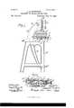
- L..K.SOOTFORD MACHINE FOR CUTTING RUBBER, TYPE.
- This invention relates to an improved machine for use in forming rubber type by cutting from a rubber sheet containinga large number of separate pieces or blocks each containing a single character and which constitute separate type bodies.
- the ordinary metal or wooden type- is commonly used as a pattern from which the rubber type is made or copied by a process involving the arrangement of the type in a form containing a large number of characters, the making of a matrix for the use of plastic material or otherwise from such form, and the molding and vulcanizing of the rubber by use of the matrix into a sheet containing a large number of characters corresponding with those of the original type form.
- the separate types or type bodies in such a sheet it is common to sever the sheet between the rows of characters so as to form strips containing a large number of characters side by side, and to then sever the strips between the characters so as to form the individual type bodies.
- the machine herein shown is more particularly intended for this latter step in the process, to wit, for severing the individual characters from the strips containing a single line or row of such characters, and is designed more particularly to facilitate and cheapen the manufacture of type in quan-v tities by severing the individual characters from a number of rubber type strips at one time or by one operation.
- Fig. 4 is a sectional view taken online 44 of Fig. 3.
- Fig. 5 is a view from beneath of a rubber type sheet after it had been cut or severed by the use of the machine.
- A indicates the horizontal bed or table of the machine which. is'mounted onv suitable legs or uprights A.
- a horizontal sliding table B- which rests and slides upon horizontal guides O O secured to the top of the table.
- a vertically reciprocating knife D which is mounted at the lower end of the upright reciprocating bar or plunger E which is held and guided in the upper end of an overhanging frame F attached to the table A at the rear of the carriage B.
- Said carriage as herein sho wn.
- the upper surface of said table B is provided with small parallel grooves b b arranged at equal distances apart and parallel with the guides O O.
- Said guides G O are shown as cast integral with the base plate 0' which is secured by a bolt 0 or otherwise to the machine table A.
- the plate 0 At its rear edge or side which is remote from theoperator the plate 0 is provided with an outwardly extending arm or flange O carrying at its upper end a guide G which is located at the rear edge of the table B but which overlaps or extends forward over'the uppersu'rface of said table.
- Said guide G is provided with a transverse groove or notch 9 adapted to engage the rear portion of the knifeD, which knife extends from front to rear over the top of the table or at right angles to the direction of motion of the same.
- the said knife D is shown as attached to a cross head E secured to the lower end of the plunger E, which latter is held at its side margins in upright parallel guide grooves ff at the forward end of the arm F, as clearly seen in Figs.
- a lever H is forward through the slot in said plunger and engages a central opening e in a block E which is attached to the front surface of the plunger.
- Said lever ll is curved downwardly and forwardly and terminates at a point near the level of the floor in front of the machine, where it is provided with an end piece 71. whereby the lever may be operated. by the foot of an attendant seated before the machine to actuate the cutting knife, the parts being so arranged that the cutting knife will be depressed when the lower end of the lever II is swung rearwardly or away from the operator.
- a suitable device is provided by which the operator may move the table B along the ways or guides C C.
- Such device is herein shown consisting of a short horizontal shaft I mounted in the plate 0 and extending forwardly therefrom at the center of the front of the machine.
- Said shaftI is provided with a small gear wheel or pinion I which engages the rack 13 formed on or attached to the lower surface of the carriage B.
- the shaft I is provided with a milled head or hand wheel I by grasping which the operator may turn the shaft 1 in either direction and thus move the table backward and forward or to right and left as desired.
- the table B At one side or end, preferably the left hand side, of the table B the latter is provided with a guide strip J secured thereto in such manner as to form a transverse guide surface or ledge against which the type strips placed on the surface of the table for cutting may be brought in order to maintain the characters thereon in alignment with each other during the process of cutting.
- This guide strip J preferably consists of a strip of rubber, wood, or other material which may be cut by a knife and which is glued or cemented to the down surface of the table B
- the use of material which may be cut by a knife, as described, is preferred in order that the front or working edge of the said guide may be formed or cut by the action of the knife of the machine after the parts are assembled, so that in case the knife is slightly bent or curved, or if it is not exactly at right angles with the path of the table, the working face of the guide will be correspondingly curved or inclined thereby insuring that such irregularity in the knife will have no efiect on the accuracy of the work in cutting the individual letters or characters from the rub ber strips.
- the rubber type sheets when taken from the mold in which they are formed have edges which are more or less irregular, but the figures or characters thereon are arranged in straight lines extending lengthwise and crosswise with the sheet.
- a first step in the making of a separate or individual type from the type sheet the latter is first severed between the horizontal rows or lines of type by means of a suitable cutting knife and preferably by the use of a machine similar to that herein shown, but one which is commonly constructed without a movable cutting table.
- the strips thus formed contain a single line or row of characters but are rough or unfinished at their ends.
- a number of the strips which it is desired to cut at once are now placed upon the table with their ends against the guide strip J at the end of the table and the side edge of the rearmost strip against the stationary guide G at the rear edge of the table.
- the table is then moved to bring the advanced ends or the strips adjacent to the edge of the cutting knife.
- the knife is then lowered so as to just clear the body part of the strip but low enough to strike the sides of the characters which project above the body of the strips, and the strips are then pushed or shifted endwise until the end characters are all uniformlya little pressed against the edge of the knife.
- the knife is then depressed with the result of severing the rough ends of all of the strips at points equi-distantto the several characters nearest the ends of the strips.
- the several strips are then turned bodily around so as to bring the cut off ends against the guide J and the strips are all pushed endwise against the said guide so as to bring the characters on the several strips exactly in line with each other from front to rear of the table.
- the table is then moved to bring the end characters which are nearest the knife up to the latter and the knife is then depressed, thereby severing all of the rough ends from the opposite ends of the strips from those first operated upon.
- the strips will then be properly arranged for the action of the knife in severing them into separate type bodies, and this will be done by moving the carriage forward step by step a distance each time suff cient to bring the knife between the rows of characters, the out being made in each instance as close as possible to the left hand side of the characters, so that the location of the characters themselves on the type bodies will be uniform.
- the guide strip J is preferably made of rubber, wood, or other material which can be cut by the knife of the machine, and the edge of said guide against which the type strips are placed is finished by being cut by the knife itself after all the parts are assembled.
- the purpose of providing the table with small parallel grooves b b is to avoid completely severing the individual types from the type strip but to leave the same connected by minute threadsof rubberso thattheindividual types will be held together in the handling and sale of the same, but may be easily dotached 0r pulledapart before they are used. It is desirable, however, for this purpose that the types in the line of type should be connected in more than one place, because ,if joined at single points only the connected line of type would easily become twisted or tangled in handling it and the grooves b b are therefore placed so close together as to give more than one line of connection in the smallest type. This will be clearly seen from Fig.
- each horizontal line or row of characters on the sheet will commonly constitute what is known as a font of type; that is to say, it will contain all of the letters of the alphabet and both the upper and lower case letters, most of the letters being repeated several times so as to afford the proper proportion of letters as common in making up concert type for ordinary printing;
- Each line therefore, after it has been severed by the machine described will consist of a series of types connected by minute threads or filaments as described, and will constitute a single small font adapted for use with a type holder in a dating stamp or the like.
- a cutting machine for rubber type comprising a vertically reciprocating knife and a sliding carriage movable beneath and in a direction at right angles to the cutting edge of the knife, said table being provided in its uppersu rface with a plurality of parallel grooves placed close together and arranged parallel with the path of the table, substantially as described.
- a cutting machine for rubber type comprising a vertically reciprocating knife, a horizontally movable table beneath the same, a stationary guide overhanging the edge of the table provided with a notch to receive the knife, a guide carried by the table, and means forgiving endwise movement to the table, sub stantially as described.
Landscapes
- Life Sciences & Earth Sciences (AREA)
- Forests & Forestry (AREA)
- Engineering & Computer Science (AREA)
- Mechanical Engineering (AREA)
- Control Of Cutting Processes (AREA)
Description
(No Model.) 2 Sheets-Sheet I.
L..K.SOOTFORD. MACHINE FOR CUTTING RUBBER, TYPE.
No. 531,069. Pat ted Dec. 18, 1894. //E
illll u: NORRIS vrrtlps ca, FHOTD-LITHO. wnsnmzrrcu, n. c.
(No Model.) 2 Sheets-Sheet 2.
L. K. SGOTPORD. MAGHINE FOR CUTTING RUBBER TYPE.
N0. 531,069. Patented D60. 18, 1894.
I Wmaw I JhrezzZ /i I gl mw/ limzzsKScoyfom Tn: NORRIS PETERS cu..mo1'o-uTHo.. AsnmeToN n c I f ED STATES PATENT OFFICE.
LOUIS K. SOOTFORD, OF CHICAGO, ILLINOIS, ASSIGNOR TO THE SUPERIOR RUBBER TYPE COMPANY, OF SAME PLACE.
MACHINE FoR CVUT'QI'IVNG RUBBER TYPE.
. SPECIFICATION forming part of Letters Patent No. 531,069, dated December 18, 1 894.
' Application filed August 30, 18 94. serial No. 521.689- (No model.)
To all whom it may concern:'
Be it known that I, LoUIs K. SCOTFORD, of Chicago, in the county of Cook and State of Illinois, have invented certain new and useful Improvements in Machines for Cutting Rubber Type; and I do hereby declare that the following is a full, clear, and exact description thereof, reference being had to the accompanying drawings, and to the letters of reference marked thereon, which form a part of this specification.
This invention relates to an improved machine for use in forming rubber type by cutting from a rubber sheet containinga large number of separate pieces or blocks each containing a single character and which constitute separate type bodies.
In the manufacture of rubber type the ordinary metal or wooden type-is commonly used as a pattern from which the rubber type is made or copied by a process involving the arrangement of the type in a form containing a large number of characters, the making of a matrix for the use of plastic material or otherwise from such form, and the molding and vulcanizing of the rubber by use of the matrix into a sheet containing a large number of characters corresponding with those of the original type form. In making the separate types or type bodies in such a sheet it is common to sever the sheet between the rows of characters so as to form strips containing a large number of characters side by side, and to then sever the strips between the characters so as to form the individual type bodies. The machine herein shown is more particularly intended for this latter step in the process, to wit, for severing the individual characters from the strips containing a single line or row of such characters, and is designed more particularly to facilitate and cheapen the manufacture of type in quan-v tities by severing the individual characters from a number of rubber type strips at one time or by one operation.
In the accompanying drawings illustrating 3-3 of Fig. 2. Fig. 4 is a sectional view taken online 44 of Fig. 3. Fig. 5 is a view from beneath of a rubber type sheet after it had been cut or severed by the use of the machine.
As shown in said drawings, A indicates the horizontal bed or table of the machine which. is'mounted onv suitable legs or uprights A. Mounted on the top of the frame A at the front thereof is a horizontal sliding table B- which rests and slides upon horizontal guides O O secured to the top of the table. Above the table is located a vertically reciprocating knife D which is mounted at the lower end of the upright reciprocating bar or plunger E which is held and guided in the upper end of an overhanging frame F attached to the table A at the rear of the carriage B. Said carriage, as herein sho wn. consists of a bed plate 3' provided on its end surface with grooves Z) b engaging the guides O C and a cutting table B on which the work rests and which is made of wood, lead, or other material against which the cutting edge of the knife may act withoutinj ury to the said cutting edge. The upper surface of said table B is provided with small parallel grooves b b arranged at equal distances apart and parallel with the guides O O. Said guides G O are shown as cast integral with the base plate 0' which is secured by a bolt 0 or otherwise to the machine table A. a At its rear edge or side which is remote from theoperator the plate 0 is provided with an outwardly extending arm or flange O carrying at its upper end a guide G which is located at the rear edge of the table B but which overlaps or extends forward over'the uppersu'rface of said table. Said guide G is provided with a transverse groove or notch 9 adapted to engage the rear portion of the knifeD, which knife extends from front to rear over the top of the table or at right angles to the direction of motion of the same. The said knife D is shown as attached to a cross head E secured to the lower end of the plunger E, which latter is held at its side margins in upright parallel guide grooves ff at the forward end of the arm F, as clearly seen in Figs. 1 and 2. For actuating the plunger E and the knife attached thereto a lever H is forward through the slot in said plunger and engages a central opening e in a block E which is attached to the front surface of the plunger. Said lever ll is curved downwardly and forwardly and terminates at a point near the level of the floor in front of the machine, where it is provided with an end piece 71. whereby the lever may be operated. by the foot of an attendant seated before the machine to actuate the cutting knife, the parts being so arranged that the cutting knife will be depressed when the lower end of the lever II is swung rearwardly or away from the operator.
A suitable device is provided by which the operator may move the table B along the ways or guides C C. Such device is herein shown consisting of a short horizontal shaft I mounted in the plate 0 and extending forwardly therefrom at the center of the front of the machine. Said shaftI is provided with a small gear wheel or pinion I which engages the rack 13 formed on or attached to the lower surface of the carriage B. At its outer or forward end the shaft I is provided with a milled head or hand wheel I by grasping which the operator may turn the shaft 1 in either direction and thus move the table backward and forward or to right and left as desired.
At one side or end, preferably the left hand side, of the table B the latter is provided with a guide strip J secured thereto in such manner as to form a transverse guide surface or ledge against which the type strips placed on the surface of the table for cutting may be brought in order to maintain the characters thereon in alignment with each other during the process of cutting. This guide strip J preferably consists of a strip of rubber, wood, or other material which may be cut by a knife and which is glued or cemented to the down surface of the table B The use of material which may be cut by a knife, as described, is preferred in order that the front or working edge of the said guide may be formed or cut by the action of the knife of the machine after the parts are assembled, so that in case the knife is slightly bent or curved, or if it is not exactly at right angles with the path of the table, the working face of the guide will be correspondingly curved or inclined thereby insuring that such irregularity in the knife will have no efiect on the accuracy of the work in cutting the individual letters or characters from the rub ber strips.
The advantages gained by constructing the cutting device in the particular manner described and shown will be more fully understood from the following description of the operation of the machine in cutting the type.
The rubber type sheets when taken from the mold in which they are formed have edges which are more or less irregular, but the figures or characters thereon are arranged in straight lines extending lengthwise and crosswise with the sheet. As a first step in the making of a separate or individual type from the type sheet the latter is first severed between the horizontal rows or lines of type by means of a suitable cutting knife and preferably by the use of a machine similar to that herein shown, but one which is commonly constructed without a movable cutting table. The strips thus formed contain a single line or row of characters but are rough or unfinished at their ends. A number of the strips which it is desired to cut at once are now placed upon the table with their ends against the guide strip J at the end of the table and the side edge of the rearmost strip against the stationary guide G at the rear edge of the table. The table is then moved to bring the advanced ends or the strips adjacent to the edge of the cutting knife. The knife is then lowered so as to just clear the body part of the strip but low enough to strike the sides of the characters which project above the body of the strips, and the strips are then pushed or shifted endwise until the end characters are all uniformlya little pressed against the edge of the knife. The knife is then depressed with the result of severing the rough ends of all of the strips at points equi-distantto the several characters nearest the ends of the strips. The several strips are then turned bodily around so as to bring the cut off ends against the guide J and the strips are all pushed endwise against the said guide so as to bring the characters on the several strips exactly in line with each other from front to rear of the table. The table is then moved to bring the end characters which are nearest the knife up to the latter and the knife is then depressed, thereby severing all of the rough ends from the opposite ends of the strips from those first operated upon. The strips will then be properly arranged for the action of the knife in severing them into separate type bodies, and this will be done by moving the carriage forward step by step a distance each time suff cient to bring the knife between the rows of characters, the out being made in each instance as close as possible to the left hand side of the characters, so that the location of the characters themselves on the type bodies will be uniform.
The object gained by bringing the projecting parts of the characters against the knife in making the first cut and preparatory to severing the first row of types will of course be understood, it being clear that the ends of the strips are raised against the guide J and must first be severed at a uniform distance from the characters at that end of the strips in order that the said characters may come exactly in alignment with each other when the strips are finally reversed and arranged fol-cutting in a mannershown in thedrawings.
As before stated, the guide strip J is preferably made of rubber, wood, or other material which can be cut by the knife of the machine, and the edge of said guide against which the type strips are placed is finished by being cut by the knife itself after all the parts are assembled. By so doing all irregularity in cutting the type from the strips which would result from inaccuracy in the placing of the knife or a failure to secure adjustment of the knife exactly parallel with the working edge of the guide J is avoided, it being obvious that if the said working edge of the guide J is cut with a knife it will be or not.
An important advantage is gained by the construction in which the rear guide G is stationary and overhangs the cutting surface or table B It is obvious that if the rear guide were attached to the table it would be necessary to push the rear end of the cutting knife so as to pass in front of the guide, and in that case it would be difficult if not impossible to maintain the end of the knife so close to the guide as to entirely sever the rearmost type strip, or that whichis' placed in contact with said guide. Similarly, if a stationary guide were used which did not overlap the table a groove or space would be formed between the rear edge of the table and the guide in which a part of the rubber strip nearest the guide would be squeezed by the downward pressure of the knife, so the knife would fail to entirely sever the said type strip; and at the same time it would be difficult to adjust the end of the knife so closeto the guide as to certainly sever the strip which is in contact with the guide. By making the guide G stationary and providing it with a notch 9 through which the knife moves and by making the guide to overhang the table, as shown, all the objections referredto are avoided, it being obvious that by extending the rear end of the knife past the working surface of the said guide G the strip nearest the guide would be acted on throughout its entire width, and that the said strip nearest the guide would be supported by the table in making the final part of the cut in the same manner as are the other strips.
. The purpose of providing the table with small parallel grooves b b is to avoid completely severing the individual types from the type strip but to leave the same connected by minute threadsof rubberso thattheindividual types will be held together in the handling and sale of the same, but may be easily dotached 0r pulledapart before they are used. It is desirable, however, for this purpose that the types in the line of type should be connected in more than one place, because ,if joined at single points only the connected line of type would easily become twisted or tangled in handling it and the grooves b b are therefore placed so close together as to give more than one line of connection in the smallest type. This will be clearly seen from Fig. 5, which isa rear, underneath view of a series of type strips after they have been severed in both directions, this figure clearly showing the plurality of connections between .the individual types of each strip which are formed by reason of the presence of the grooves in the table B It will, of course, be understood that the presence of the minute connections described after the action of the cutting knife is due to the fact that the rubber at the lower face of the sheet yields or is squeezed downwardly to the grooves so that the rubber is entirely severed only at the prominences or ridges between the grooves where the knife comes in actual contact with the surface of the table.
. In casting or making the type sheets which are to be cut or severed by the machine to form single types each horizontal line or row of characters on the sheet will commonly constitute what is known as a font of type; that is to say, it will contain all of the letters of the alphabet and both the upper and lower case letters, most of the letters being repeated several times so as to afford the proper proportion of letters as common in making up concert type for ordinary printing; Each line, therefore, after it has been severed by the machine described will consist of a series of types connected by minute threads or filaments as described, and will constitute a single small font adapted for use with a type holder in a dating stamp or the like. 'Aprincipal object, therefore, of leaving the separate types in each row connected by filaments at their lower ends or edges, as described, is to enable each small font to be handled and sold ble movable beneath the same at right angles to the cutting edge of the knife, stationary guide overlapping the table at the side edge of the same, and a guide attached to the table at the end of the same, substantially as described.
2. A cutting machine for rubber type com prising a vertically reciprocating knife, a table movable beneath the same at right angles to the cutting edge of the knife, stationary guide overlapping the table at the side edge of the same, a guide attached to the table at the end of the same, said stationary guide being provided witha notch to receive-the knife, substantially as described.
3. A cutting machine for rubber typecomprising a vertically reciprocating knife and a sliding carriage movable beneath and in a direction at right angles to the cutting edge of the knife, said table being provided in its uppersu rface with a plurality of parallel grooves placed close together and arranged parallel with the path of the table, substantially as described.
4. A cutting machine for rubber type comprising a vertically reciprocating knife, a horizontally movable table beneath the same, a stationary guide overhanging the edge of the table provided with a notch to receive the knife, a guide carried by the table, and means forgiving endwise movement to the table, sub stantially as described.
5. A cutting machine for rubber type com- LOUIS K. SCOTFORD.
lVitn esses:
TAYLOR S. BROWN, WM. S. HALL.
Publications (1)
| Publication Number | Publication Date |
|---|---|
| US531069A true US531069A (en) | 1894-12-18 |
Family
ID=2599848
Family Applications (1)
| Application Number | Title | Priority Date | Filing Date |
|---|---|---|---|
| US531069D Expired - Lifetime US531069A (en) | scotford |
Country Status (1)
| Country | Link |
|---|---|
| US (1) | US531069A (en) |
Cited By (1)
| Publication number | Priority date | Publication date | Assignee | Title |
|---|---|---|---|---|
| US20050069947A1 (en) * | 2001-07-16 | 2005-03-31 | Erlanger Bernard F. | Antibodies specific for nanotubes and related methods and compositions |
-
0
- US US531069D patent/US531069A/en not_active Expired - Lifetime
Cited By (1)
| Publication number | Priority date | Publication date | Assignee | Title |
|---|---|---|---|---|
| US20050069947A1 (en) * | 2001-07-16 | 2005-03-31 | Erlanger Bernard F. | Antibodies specific for nanotubes and related methods and compositions |
Similar Documents
| Publication | Publication Date | Title |
|---|---|---|
| US531069A (en) | scotford | |
| US509854A (en) | Machine for cutting tags | |
| US1340966A (en) | Lumber-marking machine | |
| US1622256A (en) | Valve-hole-punching machine for inner tubes | |
| US494546A (en) | Stencil-machine | |
| US641177A (en) | Machine for forming and driving staples. | |
| US236162A (en) | Mechanism for cutting out heel-lifts | |
| US757151A (en) | Automatic carving-machine. | |
| US496373A (en) | The morris peters co | |
| US2065621A (en) | Machine for operating upon sheet materials | |
| US124352A (en) | Improvement in paper-cutting machines | |
| US1068990A (en) | Wood-fastener machine. | |
| US988365A (en) | Pegging-machine. | |
| US1078147A (en) | Nail making and driving machine. | |
| US2172502A (en) | Machine for operating upon sheet material | |
| US1806195A (en) | Glazier's-point machine | |
| US1289522A (en) | Punch and shear press. | |
| US964614A (en) | Machine for notching and slitting strips. | |
| US1190151A (en) | Machine for groving boxes. | |
| US111863A (en) | Improvement in the manufacture of shoe-shanks | |
| US1755994A (en) | Hot punching and shearing machine | |
| US1220059A (en) | Vania | |
| US1451187A (en) | Brick-surfacing machine | |
| US436359A (en) | Machine for cutting shoe-soles | |
| US1856108A (en) | Slug profiling machine |