US5309057A - Weighted transducer for surface acoustic wave filter - Google Patents
Weighted transducer for surface acoustic wave filter Download PDFInfo
- Publication number
- US5309057A US5309057A US07/921,921 US92192192A US5309057A US 5309057 A US5309057 A US 5309057A US 92192192 A US92192192 A US 92192192A US 5309057 A US5309057 A US 5309057A
- Authority
- US
- United States
- Prior art keywords
- overlap
- transducer
- fingers
- transducer fingers
- acoustic wave
- Prior art date
- Legal status (The legal status is an assumption and is not a legal conclusion. Google has not performed a legal analysis and makes no representation as to the accuracy of the status listed.)
- Expired - Lifetime
Links
Images

Classifications
-
- H—ELECTRICITY
- H03—ELECTRONIC CIRCUITRY
- H03H—IMPEDANCE NETWORKS, e.g. RESONANT CIRCUITS; RESONATORS
- H03H9/00—Networks comprising electromechanical or electro-acoustic devices; Electromechanical resonators
- H03H9/02—Details
- H03H9/125—Driving means, e.g. electrodes, coils
- H03H9/145—Driving means, e.g. electrodes, coils for networks using surface acoustic waves
- H03H9/14517—Means for weighting
- H03H9/1452—Means for weighting by finger overlap length, apodisation
Definitions
- the present invention relates to a weighted transducer applied to a surface acoustic wave filter.
- an SAW (Surface Acoustic Wave) filter is an element used for obtaining filter characteristics as follows.
- An IDT (interdigital transducer) which is obtained by properly weighting an excited intensity therein is arranged in a piezoelectric substrate surface, and an SAW is transmitted and received by the IDT.
- amplitude and phase characteristics can be arbitrarily and independently designed.
- an apodized method is mainly used as a conventional weighted transducer used for a surface acoustic wave filter of this type. As shown in FIG. 2A, according to the apodized method, overlap widths between transducer fingers 21 and 22 are locally changed in proportion to a weighting function. Note that reference numerals 23 and 24 denote bus bars to which the transducer fingers 22 and 21 are respectively connected.
- a withdrawal method is used in the same manner as described above.
- the density of the transducer fingers 31 and 32 having the overlap width W is proportional to a weighting function.
- reference numerals 33 and 34 denote bus bars to which the transducer fingers 32 and 31 are respectively connected.
- FIGS. 2B and 3B show a surface acoustic wave energy distribution 25 in the apodized method and a surface acoustic wave energy distribution 35 in the withdrawal method, respectively.
- reference symbols L represent distances from the bus bars 24 and 34, respectively.
- weighted transducers have drawbacks respectively inherent thereto and have been selectively used depending on applications. That is, in the apodized method shown in FIG. 2A and 2B, a weighting function can be faithfully represented by the overlap width W, and the filter characteristics of a portion having a small weighting function, i.e., a portion having a narrow overlap width W are easily degraded by an error caused by a diffraction effect.
- the energy distribution 25 excited from the transducer is not uniform due to the transverse distribution of weighting functions and causes a weighting loss.
- a weighted transducer for a surface acoustic wave filter comprising first overlap transducer fingers formed on a surface of a piezoelectric substrate and having overlap widths continuously changed in a propagation direction of a surface acoustic wave, and second overlap transducer fingers which are alternately adjacent to the first overlap transducer fingers in a longitudinal direction of the first overlap transducer fingers, formed on the surface of the piezoelectric substrate to be electrically connected to each other in parallel and reverse-biased, and have overlap widths of the second overlap transducer fingers continuously changed in the propagation direction of the surface acoustic wave, wherein a sum of the overlap widths of the first and second overlap transducer fingers is always set to be constant in the propagation direction of the surface acoustic wave.
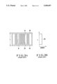
- FIGS. 1A and 1B are views for explaining an arrangement of a weighted transducer for a surface acoustic wave filter according to an embodiment of the present invention
- FIGS. 2A and 2B are views for explaining an arrangement of an apodized transducer pattern serving as a conventional weighted transducer for a surface acoustic wave filter;
- FIGS. 3A and 3B are views for explaining a withdrawal transducer pattern serving as a conventional weighted transducer for a surface acoustic wave filter.
- FIGS. 1A and 1B explain an arrangement of a weighted transducer for a surface acoustic wave filter according the embodiment of the present invention.
- FIG. 1A shows the weighted transducer for a surface acoustic wave filter
- FIG. 1B shows a surface acoustic wave energy distribution.
- reference numerals 11 and 12 denote two different sets of overlap transducer fingers.
- the hot terminals of the overlap transducer fingers 11 and 12 are connected to a common bus bar 15, and the ground terminals of the transducer fingers 11 and 12 are connected to bus bars 13 and 14, respectively, to be grounded, thereby electrically connecting the transducer fingers 11 and 12 in parallel and reverse-biasing them.
- the odd-numbered transducer fingers of the overlap transducer fingers 11 and the even-numbered transducer fingers of the overlap transducer fingers 12 are connected to a bias source (not shown) as hot terminal transducer fingers by the common bus bar 15, and the even-numbered transducer fingers of the overlap transducer fingers 11 and the odd-numbered transducer fingers of the overlap transducer fingers 12 are grounded by the bus bars 13 and 14, respectively, as ground terminal transducer fingers.
- a bias source not shown
- a sum (W 1 +W 2 ) or overlap widths W 1 and W 2 of the overlap transducer fingers 11 and 12 is set to be constant regardless of the positions of the overlap transducer fingers 11 and 12.
- the polarities of the overlap transducer fingers 11 and 12 are reversed to each other in a reverse-biased state with respect to the common bus bar 15, and the strength of a surface acoustic wave excited from the overlap widths W 1 and W 2 is proportional to (W 1 -W 2 ). Therefore, as shown in FIG. 1B, a uniform surface acoustic wave energy distribution 16 can be obtained.
- an overlap width is constant (W 1 +W 2 ) regardless of positions
- the effective excitation strength of a surface acoustic wave is proportional to a difference in overlap widths of first and second overlap transducer fingers
- degradation which is a drawback of a conventional apodized transducer and caused by a diffraction effect is very small, and there are no limits in design caused by a quantization error as in a conventional withdrawal transducer. Therefore, the present invention can be freely applied.
- a high impedance caused by a decrease in excitation effect due to a weighting operation cannot be inevitably prevented in a conventional technique.
- the first and second overlap transducer fingers are electrically connected to each other in parallel, an impedance can be maintained to be low. This is considerably effective to improve the performance of the surface acoustic wave filter.
Abstract
Description
Claims (3)
Applications Claiming Priority (2)
| Application Number | Priority Date | Filing Date | Title |
|---|---|---|---|
| JP3230824A JP2738179B2 (en) | 1991-08-19 | 1991-08-19 | Weighted electrodes for surface acoustic wave filters |
| JP3-230824 | 1991-08-19 |
Publications (1)
| Publication Number | Publication Date |
|---|---|
| US5309057A true US5309057A (en) | 1994-05-03 |
Family
ID=16913861
Family Applications (1)
| Application Number | Title | Priority Date | Filing Date |
|---|---|---|---|
| US07/921,921 Expired - Lifetime US5309057A (en) | 1991-08-19 | 1992-07-29 | Weighted transducer for surface acoustic wave filter |
Country Status (2)
| Country | Link |
|---|---|
| US (1) | US5309057A (en) |
| JP (1) | JP2738179B2 (en) |
Cited By (3)
| Publication number | Priority date | Publication date | Assignee | Title |
|---|---|---|---|---|
| EP0735672A2 (en) * | 1995-03-31 | 1996-10-02 | Siemens Aktiengesellschaft | Dual surface acoustic wave transducer for dual filter, in particular for television receivers |
| WO2010000122A1 (en) * | 2008-07-04 | 2010-01-07 | 无锡市好达电子有限公司 | A dual channel saw filter |
| DE10309250B4 (en) * | 2003-03-03 | 2015-10-22 | Epcos Ag | Electroacoustic transducer for surface wave device |
Families Citing this family (1)
| Publication number | Priority date | Publication date | Assignee | Title |
|---|---|---|---|---|
| JP2010239396A (en) * | 2009-03-31 | 2010-10-21 | Taiyo Yuden Co Ltd | Surface acoustic wave device |
Citations (1)
| Publication number | Priority date | Publication date | Assignee | Title |
|---|---|---|---|---|
| US4604595A (en) * | 1982-06-16 | 1986-08-05 | Murata Manufacturing Co., Ltd. | Surface acoustic wave device having interdigitated comb electrodes weighted for odd/even response |
-
1991
- 1991-08-19 JP JP3230824A patent/JP2738179B2/en not_active Expired - Fee Related
-
1992
- 1992-07-29 US US07/921,921 patent/US5309057A/en not_active Expired - Lifetime
Patent Citations (1)
| Publication number | Priority date | Publication date | Assignee | Title |
|---|---|---|---|---|
| US4604595A (en) * | 1982-06-16 | 1986-08-05 | Murata Manufacturing Co., Ltd. | Surface acoustic wave device having interdigitated comb electrodes weighted for odd/even response |
Non-Patent Citations (4)
| Title |
|---|
| Herbert Matthews, "Surface Wave Filter", John Wiley & Sons, Inc., 1977, pp. vii-viii. |
| Herbert Matthews, Surface Wave Filter , John Wiley & Sons, Inc., 1977, pp. vii viii. * |
| M. Hikita et al., "Phase Weighting for Low Loss Saw Filters", 1980 Ultrasonics Symposium, IEEE, pp. 308-316. |
| M. Hikita et al., Phase Weighting for Low Loss Saw Filters , 1980 Ultrasonics Symposium, IEEE, pp. 308 316. * |
Cited By (6)
| Publication number | Priority date | Publication date | Assignee | Title |
|---|---|---|---|---|
| EP0735672A2 (en) * | 1995-03-31 | 1996-10-02 | Siemens Aktiengesellschaft | Dual surface acoustic wave transducer for dual filter, in particular for television receivers |
| EP0735672A3 (en) * | 1995-03-31 | 1997-02-05 | Siemens Ag | Dual surface acoustic wave transducer for dual filter, in particular for television receivers |
| US5867075A (en) * | 1995-03-31 | 1999-02-02 | Siemens Aktiengesellschaft | Surface wave dual converter for a dual filter in particular for television sets |
| DE10309250B4 (en) * | 2003-03-03 | 2015-10-22 | Epcos Ag | Electroacoustic transducer for surface wave device |
| WO2010000122A1 (en) * | 2008-07-04 | 2010-01-07 | 无锡市好达电子有限公司 | A dual channel saw filter |
| US8232852B2 (en) | 2008-07-04 | 2012-07-31 | Shoulder Electronics Co., Ltd. | Dual-track surface-wave filter |
Also Published As
| Publication number | Publication date |
|---|---|
| JPH0548374A (en) | 1993-02-26 |
| JP2738179B2 (en) | 1998-04-08 |
Similar Documents
| Publication | Publication Date | Title |
|---|---|---|
| EP0633659B1 (en) | Surface acoustic wave filter | |
| EP0633660B1 (en) | Surface acoustic wave filter | |
| US5952899A (en) | Ladder filter having edge reflection type saw resonators | |
| KR100280609B1 (en) | Surface acoustic wave filter | |
| EP0921636A3 (en) | Surface acoustic wave filter and multistage surface acoustic wave filter | |
| US4044321A (en) | Surface acoustic wave band pass filtering | |
| JP2560991B2 (en) | Surface acoustic wave filter | |
| US4604595A (en) | Surface acoustic wave device having interdigitated comb electrodes weighted for odd/even response | |
| US5309057A (en) | Weighted transducer for surface acoustic wave filter | |
| US4506239A (en) | Compound surface acoustic wave matched filters | |
| US5336957A (en) | Surface acoustic wave convolver | |
| US4701657A (en) | Dispersive interdigital transducer for arrangements operating with acoustic waves | |
| US4263571A (en) | Surface acoustic wave filter | |
| CN100490320C (en) | Surface acoustic wave device | |
| EP0899874B1 (en) | Surface acoustic wave filter of multistage connection type | |
| EP0802627A1 (en) | Surface acoustic wave converter and acoustic wave filter using the same | |
| US6534896B2 (en) | Spatial harmonic transducers for surface wave devices | |
| US4733207A (en) | Surface acoustic wave filters | |
| US6762534B2 (en) | Transversally coupled resonator filter | |
| KR101035173B1 (en) | A boundary acoustic wave device, and a communicator using the same | |
| US5781083A (en) | Surface wave resonator having a plurality of resonance frequencies | |
| JP3432323B2 (en) | SAW device | |
| JPH0652853B2 (en) | Electrode structure of reflector type high frequency narrow band multiple mode filter | |
| GB2381975A (en) | Surface acoustic wave device | |
| US10277195B2 (en) | Electro-acoustic transducer and electro-acoustic component comprising an electro-acoustic transducer |
Legal Events
| Date | Code | Title | Description |
|---|---|---|---|
| AS | Assignment |
Owner name: NEC CORPORATION, JAPAN Free format text: ASSIGNMENT OF ASSIGNORS INTEREST.;ASSIGNOR:YAMAMOTO, YASUSHI;REEL/FRAME:006230/0115 Effective date: 19920720 |
|
| FEPP | Fee payment procedure |
Free format text: PAYOR NUMBER ASSIGNED (ORIGINAL EVENT CODE: ASPN); ENTITY STATUS OF PATENT OWNER: LARGE ENTITY |
|
| FPAY | Fee payment |
Year of fee payment: 4 |
|
| FEPP | Fee payment procedure |
Free format text: PAYOR NUMBER ASSIGNED (ORIGINAL EVENT CODE: ASPN); ENTITY STATUS OF PATENT OWNER: LARGE ENTITY Free format text: PAYER NUMBER DE-ASSIGNED (ORIGINAL EVENT CODE: RMPN); ENTITY STATUS OF PATENT OWNER: LARGE ENTITY |
|
| FPAY | Fee payment |
Year of fee payment: 8 |
|
| AS | Assignment |
Owner name: NRS TECHNOLOGIES, INC., JAPAN Free format text: ASSIGNMENT OF ASSIGNORS INTEREST;ASSIGNOR:NEC CORPORATION;REEL/FRAME:014653/0524 Effective date: 20020408 |
|
| REMI | Maintenance fee reminder mailed | ||
| STCH | Information on status: patent discontinuation |
Free format text: PATENT EXPIRED DUE TO NONPAYMENT OF MAINTENANCE FEES UNDER 37 CFR 1.362 |
|
| FP | Lapsed due to failure to pay maintenance fee |
Effective date: 20060503 |