US5307981A - Method and apparatus for optimizing bond tool pressure distribution - Google Patents
Method and apparatus for optimizing bond tool pressure distribution Download PDFInfo
- Publication number
- US5307981A US5307981A US07/993,985 US99398592A US5307981A US 5307981 A US5307981 A US 5307981A US 99398592 A US99398592 A US 99398592A US 5307981 A US5307981 A US 5307981A
- Authority
- US
- United States
- Prior art keywords
- bonding
- bonding arrangement
- arrangement
- gimbal
- providing
- Prior art date
- Legal status (The legal status is an assumption and is not a legal conclusion. Google has not performed a legal analysis and makes no representation as to the accuracy of the status listed.)
- Expired - Fee Related
Links
Images


Classifications
-
- B—PERFORMING OPERATIONS; TRANSPORTING
- B23—MACHINE TOOLS; METAL-WORKING NOT OTHERWISE PROVIDED FOR
- B23K—SOLDERING OR UNSOLDERING; WELDING; CLADDING OR PLATING BY SOLDERING OR WELDING; CUTTING BY APPLYING HEAT LOCALLY, e.g. FLAME CUTTING; WORKING BY LASER BEAM
- B23K20/00—Non-electric welding by applying impact or other pressure, with or without the application of heat, e.g. cladding or plating
- B23K20/02—Non-electric welding by applying impact or other pressure, with or without the application of heat, e.g. cladding or plating by means of a press ; Diffusion bonding
-
- B—PERFORMING OPERATIONS; TRANSPORTING
- B23—MACHINE TOOLS; METAL-WORKING NOT OTHERWISE PROVIDED FOR
- B23K—SOLDERING OR UNSOLDERING; WELDING; CLADDING OR PLATING BY SOLDERING OR WELDING; CUTTING BY APPLYING HEAT LOCALLY, e.g. FLAME CUTTING; WORKING BY LASER BEAM
- B23K2101/00—Articles made by soldering, welding or cutting
- B23K2101/36—Electric or electronic devices
- B23K2101/40—Semiconductor devices
Definitions
- This invention relates, in general, to a method of bonding leads to an integrated circuit, including, but not limited to, a method of optimizing bond tool pressure distribution.
- the present invention provides for a method of optimizing a bond tool pressure distribution, comprising the steps of providing a device having a first surface which permits inclination of the first surface in at least one direction, wherein the device is in a locked position.
- a first bonding arrangement is positioned on the first surface of the device.
- a second surface contacts the first bonding arrangement.
- the device is then unlocked to allow the first surface to incline while the second surface is in contact with the first bonding arrangement.
- the second surface is applied to the first bonding arrangement with a force, the device is locked upon application of the force.
- the method of the present invention is preferably carried out by an apparatus, comprising a device having a first surface which permits inclination of the first surface in at least one direction and a second surface capable of contacting a first bonding arrangement positioned on the first surface of the device.
- a means for determining when the second surface makes contact with the first bonding arrangement is coupled to the device.
- a means for locking and unlocking the first surface is coupled to the device and cooperates with the means for determining when the second surface makes contact with the first bonding arrangement.
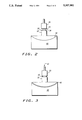
- FIG. 1 illustrates an application for the present invention
- FIG. 2 illustrates the application shown in FIG. 1 utilizing the method of the present invention in a beginning step
- FIG. 3 illustrates the application shown in FIG. 1 utilizing the method of the present invention in a further step
- FIG. 4 illustrates the application shown in FIG. 1 utilizing the method of the present invention in a further step
- FIG. 5 illustrates a functional diagram of an embodiment of the present invention.
- FIG. 1 illustrates an embodiment of an application for the present invention. What is shown is a portion of a TAB system and a bonding arrangement 10 comprised of a work piece 15, in this embodiment, a thin film tape carrier frame 15, and a semiconductor device or integrated circuit (IC) 12.
- Carrier frame 15 holds a thin film tape 14.
- Tape 14 contains a plurality of leads 16 which are bonded to a plurality of contact areas 13 on IC 12.
- IC 12 is mounted on a first surface 34 of a platform 32, which, in a preferred embodiment, also serves as a heater block.
- Bonding tool 20 is used to apply a force to bond the leads 16 of tape 14 to contact areas 13 of IC 12.
- Bonding tool 20 is shown in a very simplified form, but is actually more complex than is shown. A simplified illustration is shown because there are many variations of bonding tool 20, which is typically referred to as a thermode. An important feature of bonding tool 20 is that it have a flat bottom surface 21.
- the bottom surface 21 of bonding tool 20 be substantially coplanar or parallel with leads 16 on tape 14, with IC 12, and with first surface 34 of platform 32. If this coplanarity is not present, the bonding pressure will not be equal on all leads 16 of tape 14. This would result in nonuniform bonding of the leads 16 to IC 12. Nonuniform bonding of leads 16 means that some of the leads 16 may not be adequately bonded to IC 12, resulting in lead lifts.
- the present invention provides a method and apparatus for optimizing the coplanarity of the system in order to obtain more uniform bonding. Uniform bonding is important because variations of as little as microns can result in a finished IC 12 having inconsistent bond strengths, and in particular, lead lifts.
- FIG. 2 illustrates the application shown in FIG. 1 utilizing the method of the present invention in a beginning step.
- a portion of bonding arrangement 10 is positioned on first surface 34 of platform 32 (Bonding arrangement 10 is shown as one piece in FIGS. 2-4 to simplify the drawings).
- Platform 32 is coupled to a gimbal 40.
- Gimbal 40 is a device which permits a body to incline freely in at least one direction.
- Gimbal 40 can be comprised of a self-aligning air bearing disclosed in U.S. Pat. No. 4,934,671, issued to Laninga et al on Jun. 19, 1990, which allows for inclination in two directions and which is hereby incorporated by reference. However, a device which allows for inclination in any direction may also be used.
- gimbal 40 is shown to have an air bearing 42, which allows first surface 34 to incline or float when air pressure is provided in air bearing 42 or to be locked in a position when a vacuum is used in air bearing 42.
- gimbal 40 could be provided in either the locked or float mode by toggling a manually operated switch. If gimbal 40 is left only in the float mode, it tends to drift, resulting in bonding arrangement 10 not being coplanar at the time bonding tool 20 makes initial contact to bonding arrangement 10. If bonding arrangement 10 is not coplanar with bonding tool 20 at initial impact, the subsequent force applied by bonding tool 20 may never be equalized across bonding arrangement 10. If gimbal 40 is left only in the locked mode, variations from one bonding arrangement 10 to another will not be accounted for and will result in an unequalized amount of pressure distribution on bonding arrangement 10 from bonding tool 20. In the worst case, bonding tool 20 may never make contact with a portion of bonding arrangement 10. In addition, a manually operated switch is not well suited for a manufacturing process.
- the present invention provides a method and apparatus for optimizing the coplanarity of bonding tool 20, bonding arrangement 10 and platform 32 in order to obtain product having consistent bond strength. This is provided by providing gimbal 40 in a locked position as shown in FIG. 2. Preferably, this locked position is determined by a previously coplanar bonding arrangement substantially similar to bonding arrangement 10 to be bonded or by an initial setup routine. Bonding tool 20 then descends toward bonding arrangement 10.
- FIG. 3 illustrates the structure of FIG. 2 in a further step.
- Bonding tool 20 is lowered in the direction of arrow 50 to make contact to bonding arrangement 10.
- gimbal 40 switches to the float mode, which allows inclination of first surface 34 of platform 32. Because bonding tool 20 is contacting bonding arrangement 10, only a movement to allow pressure equalization is allowed. This equalization continues as more force is applied to bonding arrangement 10 by bonding tool 20.
- FIG. 4 illustrates the structure of FIG. 3 in a further step.
- gimbal 40 is locked when the bonding force reaches a setpoint or maximum bonding force.
- gimbal 40 may be locked prior to the application of maximum force, but somewhere in between initial contact and maximum force. It is preferable to lock gimbal 40 when maximum force is reached because coplanarity of bonding arrangement 10 and bonding tool 20 is optimized at this point.
- bonding tool 20 is raised or withdrawn from bonding arrangement 10, as shown in FIG. 2, and bonding arrangement 10 is removed from platform 32 and another bonding arrangement 10 is positioned on platform 32. Bonding of the second bonding arrangement 10 is then performed in the same manner at described with respect to FIGS. 2-4.
- gimbal 40 is provided in a locked position which was determined to be coplanar with the previous, substantially similar bonding arrangement 10. In this way, gimbal 40 is not allowed to float to an arbitrary level, which is not as optimum as the locked position of gimbal 40 in bonding the preceding bonding arrangement 10.
- FIG. 5 illustrates a functional diagram of an embodiment of the present invention.
- a means for detecting 50 when bonding tool 20 initially contacts bonding arrangement 10 is coupled to a control circuit 60 which is coupled to a means for locking and unlocking 70 gimbal 40, which is coupled to gimbal 40.
- the means for detecting 50 when bonding tool 20 initially contacts bonding arrangement 10 may be comprised of a device which can detect contact automatically, such as a circuit, a laser or a micrometer.
- Means for detecting 50 is coupled to bonding tool 20 or may be a force sensing structure built directly into bonding tool 20. If means for detecting is comprised of a circuit, then it is preferably comprised of an edge triggered variable interval timer.
- Means for detecting 50 sends a signal to control circuit 60, which processes it and sends a signal to means for locking and unlocking 70.
- means for locking and unlocking 70 is coupled to a means for providing an inert gas 80, and is, in a preferred embodiment, comprised of a valve which switches inert gas 80 on/off.
- Means for locking and unlocking 70 could be coupled to a means for providing a vacuum 90. However, it is easier to control the regulation of a flow of a gas, and therefore coupling to means for providing an inert gas 80 provides for more optimization of obtaining coplanarity of the system.
Landscapes
- Engineering & Computer Science (AREA)
- Mechanical Engineering (AREA)
- Wire Bonding (AREA)
Abstract
Description
Claims (13)
Priority Applications (1)
| Application Number | Priority Date | Filing Date | Title |
|---|---|---|---|
| US07/993,985 US5307981A (en) | 1992-12-21 | 1992-12-21 | Method and apparatus for optimizing bond tool pressure distribution |
Applications Claiming Priority (1)
| Application Number | Priority Date | Filing Date | Title |
|---|---|---|---|
| US07/993,985 US5307981A (en) | 1992-12-21 | 1992-12-21 | Method and apparatus for optimizing bond tool pressure distribution |
Publications (1)
| Publication Number | Publication Date |
|---|---|
| US5307981A true US5307981A (en) | 1994-05-03 |
Family
ID=25540156
Family Applications (1)
| Application Number | Title | Priority Date | Filing Date |
|---|---|---|---|
| US07/993,985 Expired - Fee Related US5307981A (en) | 1992-12-21 | 1992-12-21 | Method and apparatus for optimizing bond tool pressure distribution |
Country Status (1)
| Country | Link |
|---|---|
| US (1) | US5307981A (en) |
Cited By (1)
| Publication number | Priority date | Publication date | Assignee | Title |
|---|---|---|---|---|
| US5996434A (en) * | 1997-07-29 | 1999-12-07 | Swanson; David W. | Pressure head with dual horns |
Citations (4)
| Publication number | Priority date | Publication date | Assignee | Title |
|---|---|---|---|---|
| US4657170A (en) * | 1984-10-16 | 1987-04-14 | Farco, S.A. | Process for bonding an electric component to a block of connecting tags and a machine and tape for carrying out this process |
| US4934671A (en) * | 1989-04-27 | 1990-06-19 | Motorola Inc. | Self aligning air bearing platform |
| US5127573A (en) * | 1991-05-22 | 1992-07-07 | Industrial Technology Research Institute | Tape automated bonding apparatus with automatic leveling stage |
| US5150827A (en) * | 1991-11-22 | 1992-09-29 | Hughes Aircraft Company | Self-leveling reflow solder head with double pivot |
-
1992
- 1992-12-21 US US07/993,985 patent/US5307981A/en not_active Expired - Fee Related
Patent Citations (4)
| Publication number | Priority date | Publication date | Assignee | Title |
|---|---|---|---|---|
| US4657170A (en) * | 1984-10-16 | 1987-04-14 | Farco, S.A. | Process for bonding an electric component to a block of connecting tags and a machine and tape for carrying out this process |
| US4934671A (en) * | 1989-04-27 | 1990-06-19 | Motorola Inc. | Self aligning air bearing platform |
| US5127573A (en) * | 1991-05-22 | 1992-07-07 | Industrial Technology Research Institute | Tape automated bonding apparatus with automatic leveling stage |
| US5150827A (en) * | 1991-11-22 | 1992-09-29 | Hughes Aircraft Company | Self-leveling reflow solder head with double pivot |
Cited By (1)
| Publication number | Priority date | Publication date | Assignee | Title |
|---|---|---|---|---|
| US5996434A (en) * | 1997-07-29 | 1999-12-07 | Swanson; David W. | Pressure head with dual horns |
Similar Documents
| Publication | Publication Date | Title |
|---|---|---|
| US5769991A (en) | Method and apparatus for wafer bonding | |
| US6017812A (en) | Bump bonding method and bump bonding apparatus | |
| US3442432A (en) | Bonding a beam-leaded device to a substrate | |
| US5314107A (en) | Automated method for joining wafers | |
| US4954453A (en) | Method of producing an article comprising a multichip assembly | |
| US20040231600A1 (en) | Wafer carrier locking device | |
| US5667128A (en) | Workstation for processing a flexible membrane | |
| US20020081108A1 (en) | Heat treatment apparatus and method | |
| US7279358B2 (en) | Mounting method and mounting device | |
| CA2067027A1 (en) | Apparatus for peeling semiconductor substrate | |
| CA2231852C (en) | Substrate processing apparatus and method | |
| US5307981A (en) | Method and apparatus for optimizing bond tool pressure distribution | |
| US5904288A (en) | Wire bond clamping method | |
| US5040293A (en) | Bonding method | |
| US6109509A (en) | Method of securely mounting conductive balls | |
| US4362902A (en) | Ceramic chip carrier | |
| US5338705A (en) | Pressure differential downset | |
| US4913763A (en) | Die bonding apparatus | |
| JPH0521532A (en) | Tape clamp mechanism | |
| US5528070A (en) | Semiconductor sensor manufactured through anodic-bonding process | |
| JPH0793305B2 (en) | Bump forming method and bump forming apparatus | |
| EP0315655B1 (en) | Coplanar die to a silicon substrate bond method | |
| KR102726566B1 (en) | Detaching a die from an adhesive tape by air ejection | |
| JPH0715183A (en) | Electronic component mounting device | |
| US6061466A (en) | Apparatus and method for inspecting an LSI device in an assembling process, capable of detecting connection failure of individual flexible leads |
Legal Events
| Date | Code | Title | Description |
|---|---|---|---|
| AS | Assignment |
Owner name: MOTOROLA INC., ILLINOIS Free format text: ASSIGNMENT OF ASSIGNORS INTEREST.;ASSIGNORS:HECKMAN, JAMES K.;HOGGATT, MARK C.;REEL/FRAME:006362/0294 Effective date: 19921210 |
|
| FPAY | Fee payment |
Year of fee payment: 4 |
|
| FPAY | Fee payment |
Year of fee payment: 8 |
|
| AS | Assignment |
Owner name: FREESCALE SEMICONDUCTOR, INC., TEXAS Free format text: ASSIGNMENT OF ASSIGNORS INTEREST;ASSIGNOR:MOTOROLA, INC.;REEL/FRAME:015698/0657 Effective date: 20040404 Owner name: FREESCALE SEMICONDUCTOR, INC.,TEXAS Free format text: ASSIGNMENT OF ASSIGNORS INTEREST;ASSIGNOR:MOTOROLA, INC.;REEL/FRAME:015698/0657 Effective date: 20040404 |
|
| REMI | Maintenance fee reminder mailed | ||
| LAPS | Lapse for failure to pay maintenance fees |
Free format text: PATENT EXPIRED FOR FAILURE TO PAY MAINTENANCE FEES (ORIGINAL EVENT CODE: EXP.); ENTITY STATUS OF PATENT OWNER: LARGE ENTITY |
|
| STCH | Information on status: patent discontinuation |
Free format text: PATENT EXPIRED DUE TO NONPAYMENT OF MAINTENANCE FEES UNDER 37 CFR 1.362 |
|
| FP | Lapsed due to failure to pay maintenance fee |
Effective date: 20060503 |