US5289701A - Method of determining sleeve and body patterns - Google Patents
Method of determining sleeve and body patterns Download PDFInfo
- Publication number
- US5289701A US5289701A US07/932,152 US93215292A US5289701A US 5289701 A US5289701 A US 5289701A US 93215292 A US93215292 A US 93215292A US 5289701 A US5289701 A US 5289701A
- Authority
- US
- United States
- Prior art keywords
- reference point
- sleeve
- pattern
- determining
- point
- Prior art date
- Legal status (The legal status is an assumption and is not a legal conclusion. Google has not performed a legal analysis and makes no representation as to the accuracy of the status listed.)
- Expired - Lifetime
Links
- 238000000034 method Methods 0.000 title claims description 23
- 238000009940 knitting Methods 0.000 claims description 16
- 238000005259 measurement Methods 0.000 claims description 8
- 230000003247 decreasing effect Effects 0.000 description 5
- 230000012447 hatching Effects 0.000 description 2
- 238000012986 modification Methods 0.000 description 2
- 230000004048 modification Effects 0.000 description 2
- 238000009958 sewing Methods 0.000 description 2
- 238000006073 displacement reaction Methods 0.000 description 1
- 238000002474 experimental method Methods 0.000 description 1
- 239000004744 fabric Substances 0.000 description 1
- 238000004519 manufacturing process Methods 0.000 description 1
Images


Classifications
-
- D—TEXTILES; PAPER
- D04—BRAIDING; LACE-MAKING; KNITTING; TRIMMINGS; NON-WOVEN FABRICS
- D04B—KNITTING
- D04B1/00—Weft knitting processes for the production of fabrics or articles not dependent on the use of particular machines; Fabrics or articles defined by such processes
- D04B1/22—Weft knitting processes for the production of fabrics or articles not dependent on the use of particular machines; Fabrics or articles defined by such processes specially adapted for knitting goods of particular configuration
- D04B1/24—Weft knitting processes for the production of fabrics or articles not dependent on the use of particular machines; Fabrics or articles defined by such processes specially adapted for knitting goods of particular configuration wearing apparel
- D04B1/246—Upper torso garments, e.g. sweaters, shirts, leotards
Definitions
- the present invention relates to a method of determining patterns or shapes of knitted segments for efficiency knitting a knit product, e.g. a sweater or cardigan, which is also known as an integral or whole garment, with the use of a knitting machine which performs a knitting action for yielding rows of major stitches, and more particularly, a method of determining a sleeve and a body pattern which are joined in a good fit.
- a knit product e.g. a sweater or cardigan, which is also known as an integral or whole garment
- a body portion and a sleeve or other portion of a knit fabric are joined by sewing at the joining step succeeding the knitting step. This takes a considerable length of time in the production. Also, a resulting knitted product composed of the segment portions joined by sewing will exhibit less stretchability and if worse, may be torn apart along a joined seam in use.
- each sleeve portion Since the set-in end of each sleeve portion is joined to the armhole of the body portion, the two seams have to be equal to each other in the number of stitches.
- the disadvantage of the method is that the two seams can be joined with difficulty while their armhole circumferential lengths only are measured to match. In action, optimum patterns or shapes of the sleeve and body portions for desired joining will be given through a series of experiments, which will result in the loss of time.
- the method of knitting sleeve and body patterns of which shapes are determined after a number of trials is low in the productive efficiency and when modification is wanted in the shape, it has to use a troublesome cut-and-try technique.
- a method of determining a sleeve and a body pattern of a knit product which are joined to each other during a knitting operation with a knitting machine comprises the step of having the body pattern arranged so that the vertical length or height of an armhole thereof between a shoulder point and an underarm point is equal to the height of a set-in triangle region of the sleeve pattern.
- the set-in region of the sleeve pattern can be shaped into a trapezoid form which is smaller by a given distance in the height than the original triangle form.
- the pattern determining method of the present invention allows the sleeve and body patterns to be created so that the vertical length or height of the armhole of the body pattern between the shoulder end and the underarm end is equal to the height of the set-in region of the sleeve pattern. Accordingly, the sleeve pattern is neatly joined to the body pattern and is equal to it in the number of course stitches.
- the set-in region of the sleeve pattern can be shifted from the original triangle shape to a trapezoid shape for decreasing its height by any desired distance.
- the knitting is carried out by joining the wale stitches of the top side of the trapezoid shape of the sleeve pattern to the course stitches of the desired distance from the shoulder end of the armhole of the body pattern at a predetermined stitch ratio.
- Any desired shape of the set-in region of the sleeve pattern can be fabricated according to the method of the present invention.
- FIGS. 1 to 3 are explanatory views showing patterns which are fabricated by a method of the present invention
- FIGS. 4 and 5 are explanatory views of a sleeve pattern joined to a body pattern
- FIGS. 6 to 9 are explanatory views showing stitch-to-stitch movements in joining the sleeve pattern to the body pattern.
- FIG. 10 is a front view of a sweater knitted according to the present invention.
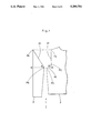
- FIGS. 1 and 2 show the right half of a set-in-sleeve sweater of which segment patterns are determined by the method of the present invention, while the left half is not illustrated for ease of explanation.
- a sweater 1 is composed of a sleeve pattern 2 and a body pattern 3.
- the width of the sleeve pattern 2 is measured from a reference point P9 at the underarm to a point B on the horizontal line extending from the point P9.
- the distance from the point B to its overhead point P4 is designated to match a sleeve set-in measurement.
- the extension of an armhole end 21 of the sleeve 2 is measured between the points P4 and P9. It is also assumed that the line between P4 and P9 is at an angle ⁇ to the horizontal line between B and P9.
- the body pattern 3 has a reference point P0 located at the underarm and a first point Pl distanced by the length of a gusset horizontally from the reference point P0.
- a second point P2 is located at the intersection of the vertical shoulder-end line with the line which extends from the point P1 at the angle ⁇ to the horizontal line between P0 and P1.
- a third point P3 at the shoulder is distanced from the horizontal or reference P0 line upwardly by a length equal to the sleeve set-in measurement.
- an armhole end 31 of the body pattern 3 is extended from P0 to P1, P2 and P3.
- the point A is located at the intersection between the horizontal line from the reference point P0 and the perpendicular line fron the third or shoulder point P3.
- the sleeve patterns 2 and 3 are symmetrically shown in the left half of the set-in sleeve sweater.
- the size of an armhole determined by the armhole end 31 of the body pattern 3 is designated by a diagonal line which extends between P0 and P3.
- the length of the sleeve pattern 2 and other measurements are not specified as will be determined by individual requirements.
- each sleeve pattern is joined to the body pattern so that a point P10 beneath the reference point P9 of the sleeve pattern meets the reference point P0 of the body pattern, the point P9 of the sleeve pattern meets the point P1 of the body pattern, and the point P4 of the sleeve pattern meets the point P3 of the body pattern, as best shown in FIG. 6.
- FIG.2 Shown in FIG.2 are a sleeve pattern 2' and a body pattern 3' similar to those illustrated in FIG.1.
- the sleeve pattern 2' has an armhole end 21' which is defined by the line between the reference point P9 and the uppermost point P4 as similar to that explained in FIG.1.
- the body pattern 3' has an armhole end 31' determined by the line which extends from the reference point P0 to the points P1, P2, and P3 as is similar to that explained in FIG.1.
- a portion cut along the horizontal line which extends between two points P5 and P6 and is spaced a distance d from the uppermost point P4 is terminated.
- the corresponding point of the body pattern 3' is denoted by P7 as downwardly spaced d from the shoulder point P3.
- each sleeve pattern is joined to the body pattern through laterally displacing its armhole end stitches wale by wale towards the body pattern as shown in FIGS.4 and 5 respectively.
- the points P5, P9, and P10 of the modified sleeve pattern 2' are coincided to the points P7, P1, and P0 of the body pattern 3' respectively and the loops of yarn from P5 to P6 are placed over a row of loops from P7 to P3 in every wale as shown in FIG. 7.
- the excess of the stitches can be offset by adding a series of stitches to the body pattern as denoted by the cross hatching in FIG.8 or by adding a series of stitches to the sleeve pattern as denoted by the cross hatching in FIG.9.
- the stitch number of d can be two times greater than w with x and y being predetermined.
- each pattern can be designed to an appropriate shape.
- a gusset of the body pattern is shortened to decrease a greater number of stitches at the underarm, as shown in FIG.3, so that the rate of stitch decreasing in the sleeve can be maintained uniform.
- the width of an original sleeve pattern is C and the length of an original gusset of a body pattern is D
- the displacement from P1 to P1' corresponding to a difference (C'-C) between the original width C and its increased width C' results in decrease of the gusset length to D'.
- the angle P1P1'P2 becomes smaller and thus, a greater number of the stitches than that in the original pattern are to be decreased.
- the measurements of a pattern are determined corresponding to the ratio between the vertical and horizontal stitches which is predetermined for the standard shape.
- a pattern of a desired shape can be fabricated, regardless of counting the number of stitches in a given length, by the method of the present invention in which the measurements of the pattern are determined corresponding to the ratio between vertical and horizontal stitches which is preset for the standard pattern.
- the method of the present invention allows a pattern to be determined at high efficiency for a knitting operation.
- the method can control a knitting machine without use of any templates.
Landscapes
- Engineering & Computer Science (AREA)
- Textile Engineering (AREA)
- Knitting Machines (AREA)
- Outer Garments And Coats (AREA)
- Knitting Of Fabric (AREA)
Abstract
A method for determining a sleeve and body pattern so that each sleeve is the same vertically as related to the body. The body is arranged so that the vertical height of an armhole between a shoulder point and an underarm point is equal in height of a set-in region of the sleeve pattern. The sleeves are joined to the body of the garment by a knitting process.
Description
The present invention relates to a method of determining patterns or shapes of knitted segments for efficiency knitting a knit product, e.g. a sweater or cardigan, which is also known as an integral or whole garment, with the use of a knitting machine which performs a knitting action for yielding rows of major stitches, and more particularly, a method of determining a sleeve and a body pattern which are joined in a good fit.
In common, a body portion and a sleeve or other portion of a knit fabric are joined by sewing at the joining step succeeding the knitting step. This takes a considerable length of time in the production. Also, a resulting knitted product composed of the segment portions joined by sewing will exhibit less stretchability and if worse, may be torn apart along a joined seam in use.
For overcoming the foregoing drawback, modified methods have been introduced which incorporate an integral or whole garment knitting technique. One such method is proposed by the same applicant as of this specification, as disclosed in Japanese Patent Laid-open Publication 2-229248(1990), in which each tubular sleeve portion is joined with a body portion during knitting action with the use of a flat knitting machine which has two pair of front and rear needle beds arranged in an upper position and a lower position respectively. front and rear sides respectively.
Since the set-in end of each sleeve portion is joined to the armhole of the body portion, the two seams have to be equal to each other in the number of stitches. The disadvantage of the method is that the two seams can be joined with difficulty while their armhole circumferential lengths only are measured to match. In action, optimum patterns or shapes of the sleeve and body portions for desired joining will be given through a series of experiments, which will result in the loss of time.
Hence, the method of knitting sleeve and body patterns of which shapes are determined after a number of trials is low in the productive efficiency and when modification is wanted in the shape, it has to use a troublesome cut-and-try technique.
In particular, if such sleeve and body patterns are joined while their length measurements are translated to stitches, it will be necessary, due to difference in the number of courses, to displace some stitches and/or adjust the number of lines. Therefore, an improved method of determining patterns for optimum joining has been wanted.
It is an object of the present invention to provide an improved method in which both a sleeve and a body pattern are simultaneously determined from the standard ratio between vertical and horizontal stitches so that assignment of stitches to the patterns can easily be implemented without any troublesome control.
According to the present invention, a method of determining a sleeve and a body pattern of a knit product which are joined to each other during a knitting operation with a knitting machine, comprises the step of having the body pattern arranged so that the vertical length or height of an armhole thereof between a shoulder point and an underarm point is equal to the height of a set-in triangle region of the sleeve pattern.
Also, for modification of the sleeve pattern or size, the set-in region of the sleeve pattern can be shaped into a trapezoid form which is smaller by a given distance in the height than the original triangle form.
In action, the pattern determining method of the present invention allows the sleeve and body patterns to be created so that the vertical length or height of the armhole of the body pattern between the shoulder end and the underarm end is equal to the height of the set-in region of the sleeve pattern. Accordingly, the sleeve pattern is neatly joined to the body pattern and is equal to it in the number of course stitches.
The set-in region of the sleeve pattern can be shifted from the original triangle shape to a trapezoid shape for decreasing its height by any desired distance. In this case, the knitting is carried out by joining the wale stitches of the top side of the trapezoid shape of the sleeve pattern to the course stitches of the desired distance from the shoulder end of the armhole of the body pattern at a predetermined stitch ratio. Any desired shape of the set-in region of the sleeve pattern can be fabricated according to the method of the present invention.
FIGS. 1 to 3 are explanatory views showing patterns which are fabricated by a method of the present invention;
FIGS. 4 and 5 are explanatory views of a sleeve pattern joined to a body pattern;
FIGS. 6 to 9 are explanatory views showing stitch-to-stitch movements in joining the sleeve pattern to the body pattern; and
FIG. 10 is a front view of a sweater knitted according to the present invention.
A method of determining patterns according to the present invention will be described referring to the accompanying drawings.
FIGS. 1 and 2 show the right half of a set-in-sleeve sweater of which segment patterns are determined by the method of the present invention, while the left half is not illustrated for ease of explanation.
As shown in FIG. 1, a sweater 1 is composed of a sleeve pattern 2 and a body pattern 3.
The width of the sleeve pattern 2 is measured from a reference point P9 at the underarm to a point B on the horizontal line extending from the point P9. The distance from the point B to its overhead point P4 is designated to match a sleeve set-in measurement. The extension of an armhole end 21 of the sleeve 2 is measured between the points P4 and P9. It is also assumed that the line between P4 and P9 is at an angle θ to the horizontal line between B and P9.
The body pattern 3 has a reference point P0 located at the underarm and a first point Pl distanced by the length of a gusset horizontally from the reference point P0. A second point P2 is located at the intersection of the vertical shoulder-end line with the line which extends from the point P1 at the angle θ to the horizontal line between P0 and P1. A third point P3 at the shoulder is distanced from the horizontal or reference P0 line upwardly by a length equal to the sleeve set-in measurement. Hence, an armhole end 31 of the body pattern 3 is extended from P0 to P1, P2 and P3. The point A is located at the intersection between the horizontal line from the reference point P0 and the perpendicular line fron the third or shoulder point P3.
The sleeve patterns 2 and 3 are symmetrically shown in the left half of the set-in sleeve sweater.
The size of an armhole determined by the armhole end 31 of the body pattern 3 is designated by a diagonal line which extends between P0 and P3. The length of the sleeve pattern 2 and other measurements are not specified as will be determined by individual requirements. When the number of stitches in a given wale length is x, and the number of stitches in a given course length is y in the patterns 2 and 3, a ratio between the distances, where the decrease of stitches, e.g. one wale in every two courses, is given at either sleeve set-in and body underarm, is expressed by: ##EQU1## Hence, ##EQU2## Then, the angle θ=tan-1 (2x/y).
It should be understood that the decrease is not limited to one wale in every two courses.
For fabricating the sweater, each sleeve pattern is joined to the body pattern so that a point P10 beneath the reference point P9 of the sleeve pattern meets the reference point P0 of the body pattern, the point P9 of the sleeve pattern meets the point P1 of the body pattern, and the point P4 of the sleeve pattern meets the point P3 of the body pattern, as best shown in FIG. 6.
A technique for modifying the standard shape of a set-in region of the sleeve pattern will now be explained.
Shown in FIG.2 are a sleeve pattern 2' and a body pattern 3' similar to those illustrated in FIG.1.
The sleeve pattern 2' has an armhole end 21' which is defined by the line between the reference point P9 and the uppermost point P4 as similar to that explained in FIG.1.
Also, the body pattern 3' has an armhole end 31' determined by the line which extends from the reference point P0 to the points P1, P2, and P3 as is similar to that explained in FIG.1.
For decreasing the set-in region of the sleeve pattern 2', a portion cut along the horizontal line which extends between two points P5 and P6 and is spaced a distance d from the uppermost point P4 is terminated.
The corresponding point of the body pattern 3' is denoted by P7 as downwardly spaced d from the shoulder point P3.
In both cases shown in FIGS.1 and 2, each sleeve pattern is joined to the body pattern through laterally displacing its armhole end stitches wale by wale towards the body pattern as shown in FIGS.4 and 5 respectively.
More particularly, the points P5, P9, and P10 of the modified sleeve pattern 2' are coincided to the points P7, P1, and P0 of the body pattern 3' respectively and the loops of yarn from P5 to P6 are placed over a row of loops from P7 to P3 in every wale as shown in FIG. 7.
If the ratio of courses between P7 and P3 to wales between P5 and P6 is not 2:1, either has an excessive number of the stitches.
The excess of the stitches can be offset by adding a series of stitches to the body pattern as denoted by the cross hatching in FIG.8 or by adding a series of stitches to the sleeve pattern as denoted by the cross hatching in FIG.9.
It is now assumed that the distance between P5 and P6 is w. As a triangle determined by the three points P4, B, and P0 is similar to a triangle determined by the points P4, P6, and P5, the equation is established as: ##EQU3## Then, ##EQU4##
When the point P5 is located at any point on the oblique line between P9 and P4, the stitch number of d can be two times greater than w with x and y being predetermined.
Also, it is a good idea that the ratios of wale and course stitches to their respective given lengths in which corresponding sleeve and body patterns are knitted and joined with a level of success are assigned as default values. Accordingly, when the number of stitches per given length is undetermined, each pattern can be designed to an appropriate shape.
For increasing the width of a sleeve pattern, a gusset of the body pattern is shortened to decrease a greater number of stitches at the underarm, as shown in FIG.3, so that the rate of stitch decreasing in the sleeve can be maintained uniform. For example, when the width of an original sleeve pattern is C and the length of an original gusset of a body pattern is D, the displacement from P1 to P1' corresponding to a difference (C'-C) between the original width C and its increased width C' results in decrease of the gusset length to D'.
As the result, the angle P1P1'P2 becomes smaller and thus, a greater number of the stitches than that in the original pattern are to be decreased.
Even if the decrease of stitches in the original sleeve pattern is carried out from P9' to P8', the result is equivalent to the stitch decrease along the diagonal line P9'P8 of a parallelogram determined by the four points P9 ,P9',P8',P8. Hence, the rate of decreasing will be maintained uniform in the sleeve pattern.
The measurements of a pattern are determined corresponding to the ratio between the vertical and horizontal stitches which is predetermined for the standard shape.
As set forth above, a pattern of a desired shape can be fabricated, regardless of counting the number of stitches in a given length, by the method of the present invention in which the measurements of the pattern are determined corresponding to the ratio between vertical and horizontal stitches which is preset for the standard pattern.
Accordingly, the method of the present invention allows a pattern to be determined at high efficiency for a knitting operation.
Also, the method can control a knitting machine without use of any templates.
Claims (2)
1. A method for determining a pattern for a sleeve and body of a knit product in which the sleeve and body are joined together during a knitting operation of a knitting machine, comprising:
determining a first reference point (P0) at an underarm connection of said body, extending a horizontal line through said reference point perpendicular to a vertical center line of said body,
determining an underarm point (P9) of said sleeve on said horizontal line spaced from said reference point (P0) a distance away from said reference point (P0) and said body, determining the number of knitting stitches along said horizontal line from reference point (P9) to reference point (B) required for a width (P9-B) of said sleeve,
determining a sleeve set-in distance (B-P4) on a first vertical line from reference point (B) to reference point (P4) and determining the number of courses along said first vertical line from reference point (B) to reference point (P4),
determining an extension of said armhole of the sleeve by measuring a distance between the sleeve set-in reference point (P4) and the underarm reference point (P9) to determine a number of stitches to be dropped as the courses are knitted between reference point (B) and reference point (P4) and to determine an angle θ formed by said horizontal line and a line form reference point (P4) through the underarm reference point (P9), to form a sleeve armhole end (21),
determining a matching sleeve pattern on said knit body related to said first reference point (P0),
determining a length of a gusset along said horizontal line from said first reference point (P0) to a reference point (P1) to determine a shoulder-end line by extending a second vertical line from reference point (P3) corresponding to a sleeve set-in measurement,
extending a line from point (P1) to said second vertical line at point (P3) and determining an angle θ with said horizontal line by extending a line from point (P1) to intersect line (P3-A) at (P2) to establish a point (P2), thereby forming an armhole end (31) of said body portion which extends from reference point (P3) to reference point (P2), from reference point (P2) to reference point (P1) and from reference point (P1) to reference point (P0) whereby the sleeve pattern and the body pattern have the same height and same number of courses.
2. A method for determining a body and sleeve pattern of a knit product including measuring distances on both the body and the sleeve portion, setting a reference point as a standard measurement, a step of establishing pattern coordinates for the knit garment, and determining a height of an armhole of a body pattern so that the height would be equal to a height of a set-in triangular region of the sleeve.
Applications Claiming Priority (2)
| Application Number | Priority Date | Filing Date | Title |
|---|---|---|---|
| JP3-206878 | 1991-08-19 | ||
| JP3206878A JP2860437B2 (en) | 1991-08-19 | 1991-08-19 | How to make a sleeve and body pattern |
Publications (1)
| Publication Number | Publication Date |
|---|---|
| US5289701A true US5289701A (en) | 1994-03-01 |
Family
ID=16530547
Family Applications (1)
| Application Number | Title | Priority Date | Filing Date |
|---|---|---|---|
| US07/932,152 Expired - Lifetime US5289701A (en) | 1991-08-19 | 1992-08-19 | Method of determining sleeve and body patterns |
Country Status (5)
| Country | Link |
|---|---|
| US (1) | US5289701A (en) |
| EP (1) | EP0529890B1 (en) |
| JP (1) | JP2860437B2 (en) |
| DE (1) | DE69214575T2 (en) |
| ES (1) | ES2093206T3 (en) |
Cited By (8)
| Publication number | Priority date | Publication date | Assignee | Title |
|---|---|---|---|---|
| US5701766A (en) * | 1995-11-24 | 1997-12-30 | Shima Seiki Manufacturing, Ltd. | Method for broadening a tubular knitted fabric by a flat knitting machine, a knit design apparatus and a memory therefor, and knitted tubular fabric |
| US6250115B1 (en) * | 1998-02-20 | 2001-06-26 | Yasuko Suzuki | Method for creating knitted garments and patterns therefor |
| WO2001064987A1 (en) * | 2000-02-29 | 2001-09-07 | Shima Seiki Mfg., Ltd. | Method of knitting neck of knit wear by weft knitting machine and the knit wear |
| US6658899B2 (en) | 2000-02-29 | 2003-12-09 | Shima Seiki Mfg., Ltd. | Method of knitting neck of knit wear by weft knitting machine and the knit wear |
| RU2326996C1 (en) * | 2006-12-13 | 2008-06-20 | Государственное образовательное учреждение высшего профессионального образования "Московский государственный текстильный университет им. А.Н. Косыгина" | Method of hose-type items knitting on flat rib machine |
| RU2326998C1 (en) * | 2006-12-13 | 2008-06-20 | Государственное образовательное учреждение высшего профессионального образования "Московский государственный текстильный университет им. А.Н. Косыгина" | Method of item knitting on flat rib machine |
| RU2326997C1 (en) * | 2006-12-13 | 2008-06-20 | Государственное образовательное учреждение высшего профессионального образования "Московский государственный текстильный университет им. А.Н. Косыгина" | Method of knitting of tubular knit item on flat knitting rib machine |
| CN112609306A (en) * | 2020-12-10 | 2021-04-06 | 斓帛职业培训学校(桐乡)有限公司 | Clamping structure weaving method and clamping structure of full-forming flat knitting machine clothing |
Families Citing this family (1)
| Publication number | Priority date | Publication date | Assignee | Title |
|---|---|---|---|---|
| JP2913266B2 (en) * | 1995-09-18 | 1999-06-28 | 株式会社島精機製作所 | Method and apparatus for designing tubular knitted fabric for flat knitting machine |
Citations (8)
| Publication number | Priority date | Publication date | Assignee | Title |
|---|---|---|---|---|
| US3035426A (en) * | 1956-08-20 | 1962-05-22 | Macqueen Kenneth Gordon | Knitting processes and knitting machines |
| US3695063A (en) * | 1969-10-31 | 1972-10-03 | Courtaulds Ltd | Knitting method and knitted garment |
| US3824810A (en) * | 1972-02-02 | 1974-07-23 | Courtaulds Ltd | Knitting method |
| DE2166569A1 (en) * | 1971-04-28 | 1974-09-05 | Schieber Universal Maschf | Jacquard knitting on flat machines - altering patterning and working width during knitting if necessary |
| US3990271A (en) * | 1975-01-07 | 1976-11-09 | Courtaulds Limited | Knitting method |
| US4192157A (en) * | 1977-03-02 | 1980-03-11 | Aisin Seiki Co., Ltd. | Knitting width indication system for knitting machines |
| US4197724A (en) * | 1977-10-04 | 1980-04-15 | Courtaulds Limited | Knitting method |
| US4398402A (en) * | 1980-03-13 | 1983-08-16 | Courtaulds Limited | Knitting method and knitted garment |
Family Cites Families (4)
| Publication number | Priority date | Publication date | Assignee | Title |
|---|---|---|---|---|
| IE33508B1 (en) * | 1968-07-22 | 1974-07-24 | Courtaulds Ltd | A knitting method |
| GB1328701A (en) * | 1970-03-31 | 1973-08-30 | Courtaulds Ltd | Knitting of garments |
| GB1487421A (en) * | 1974-02-05 | 1977-09-28 | Courtaulds Ltd | Knitting method |
| JPH02229248A (en) * | 1989-03-03 | 1990-09-12 | Shima Seiki Seisakusho:Kk | Knitting of tubular knit fabric |
-
1991
- 1991-08-19 JP JP3206878A patent/JP2860437B2/en not_active Expired - Fee Related
-
1992
- 1992-08-14 DE DE69214575T patent/DE69214575T2/en not_active Expired - Lifetime
- 1992-08-14 ES ES92307455T patent/ES2093206T3/en not_active Expired - Lifetime
- 1992-08-14 EP EP92307455A patent/EP0529890B1/en not_active Expired - Lifetime
- 1992-08-19 US US07/932,152 patent/US5289701A/en not_active Expired - Lifetime
Patent Citations (8)
| Publication number | Priority date | Publication date | Assignee | Title |
|---|---|---|---|---|
| US3035426A (en) * | 1956-08-20 | 1962-05-22 | Macqueen Kenneth Gordon | Knitting processes and knitting machines |
| US3695063A (en) * | 1969-10-31 | 1972-10-03 | Courtaulds Ltd | Knitting method and knitted garment |
| DE2166569A1 (en) * | 1971-04-28 | 1974-09-05 | Schieber Universal Maschf | Jacquard knitting on flat machines - altering patterning and working width during knitting if necessary |
| US3824810A (en) * | 1972-02-02 | 1974-07-23 | Courtaulds Ltd | Knitting method |
| US3990271A (en) * | 1975-01-07 | 1976-11-09 | Courtaulds Limited | Knitting method |
| US4192157A (en) * | 1977-03-02 | 1980-03-11 | Aisin Seiki Co., Ltd. | Knitting width indication system for knitting machines |
| US4197724A (en) * | 1977-10-04 | 1980-04-15 | Courtaulds Limited | Knitting method |
| US4398402A (en) * | 1980-03-13 | 1983-08-16 | Courtaulds Limited | Knitting method and knitted garment |
Cited By (9)
| Publication number | Priority date | Publication date | Assignee | Title |
|---|---|---|---|---|
| US5701766A (en) * | 1995-11-24 | 1997-12-30 | Shima Seiki Manufacturing, Ltd. | Method for broadening a tubular knitted fabric by a flat knitting machine, a knit design apparatus and a memory therefor, and knitted tubular fabric |
| US6250115B1 (en) * | 1998-02-20 | 2001-06-26 | Yasuko Suzuki | Method for creating knitted garments and patterns therefor |
| WO2001064987A1 (en) * | 2000-02-29 | 2001-09-07 | Shima Seiki Mfg., Ltd. | Method of knitting neck of knit wear by weft knitting machine and the knit wear |
| US6658899B2 (en) | 2000-02-29 | 2003-12-09 | Shima Seiki Mfg., Ltd. | Method of knitting neck of knit wear by weft knitting machine and the knit wear |
| RU2326996C1 (en) * | 2006-12-13 | 2008-06-20 | Государственное образовательное учреждение высшего профессионального образования "Московский государственный текстильный университет им. А.Н. Косыгина" | Method of hose-type items knitting on flat rib machine |
| RU2326998C1 (en) * | 2006-12-13 | 2008-06-20 | Государственное образовательное учреждение высшего профессионального образования "Московский государственный текстильный университет им. А.Н. Косыгина" | Method of item knitting on flat rib machine |
| RU2326997C1 (en) * | 2006-12-13 | 2008-06-20 | Государственное образовательное учреждение высшего профессионального образования "Московский государственный текстильный университет им. А.Н. Косыгина" | Method of knitting of tubular knit item on flat knitting rib machine |
| CN112609306A (en) * | 2020-12-10 | 2021-04-06 | 斓帛职业培训学校(桐乡)有限公司 | Clamping structure weaving method and clamping structure of full-forming flat knitting machine clothing |
| CN112609306B (en) * | 2020-12-10 | 2022-04-05 | 嘉兴市蒂维时装有限公司 | Clamping structure weaving method and clamping structure of full-forming flat knitting machine clothing |
Also Published As
| Publication number | Publication date |
|---|---|
| JP2860437B2 (en) | 1999-02-24 |
| JPH0551848A (en) | 1993-03-02 |
| ES2093206T3 (en) | 1996-12-16 |
| DE69214575D1 (en) | 1996-11-21 |
| EP0529890B1 (en) | 1996-10-16 |
| DE69214575T2 (en) | 1997-02-20 |
| EP0529890A1 (en) | 1993-03-03 |
Similar Documents
| Publication | Publication Date | Title |
|---|---|---|
| US5284031A (en) | Knit ply fabric with connecting layer | |
| EP0468687B1 (en) | Method for processing end portion of fabric | |
| US5553468A (en) | Brassiere and method of making same | |
| EP1116807B1 (en) | Knitting method for knit clothing | |
| EP0522778B1 (en) | Tubular knitted fabric having a three-dimensional silhouette shape and method of knitting the same | |
| EP0211641A1 (en) | Method of manufacturing knitted briefs | |
| EP1375718A1 (en) | Knitted fabric having opening portion and knitting method therefor | |
| JP3968079B2 (en) | Method for forming gusset and knitwear formed with gusset | |
| JPH04153346A (en) | Cylindrical knitted fabric having notched section | |
| US5289701A (en) | Method of determining sleeve and body patterns | |
| EP1371767A1 (en) | Method for knitting fabric | |
| JPH0415301B2 (en) | ||
| US3635051A (en) | Knitting method | |
| JP4203323B2 (en) | Knitwear with a collar knitted by a flat knitting machine and its knitting method | |
| JP4344210B2 (en) | Method for knitting knitwear having raglan sleeves and knitwear having raglan sleeves | |
| US6935140B2 (en) | Method of knitting tubular knitted fabric | |
| EP2390394A1 (en) | Method for knitting tubular fabric having neck line, and tubular fabric having neck line | |
| US6079232A (en) | Widening method | |
| US7168271B2 (en) | Method of knitting knit-wear having front neck and knit-wear having front neck | |
| US7143613B2 (en) | Knitwear garment and method of knitting knitwear | |
| EP0466439A2 (en) | Cast on method for knitting and knitted fabric formed by the same | |
| EP0449544B1 (en) | Connective knitting method of belt-shaped knit end and belt-knit fabric having the end part linked in knit state | |
| JPH07238445A (en) | Method for knitting tubular knit fabric of jacquard gray sheeting | |
| US4107955A (en) | Method of knitting blank for a sleeved garment and product thereof | |
| US2643532A (en) | Method of producing full-fashioned knitted articles |
Legal Events
| Date | Code | Title | Description |
|---|---|---|---|
| AS | Assignment |
Owner name: SHIMA SEIKI MFG., LTD. Free format text: ASSIGNMENT OF ASSIGNORS INTEREST.;ASSIGNORS:MITSUMOTO, SHIGENOBU;OKUNO, MASAO;REEL/FRAME:006239/0488 Effective date: 19920806 |
|
| FEPP | Fee payment procedure |
Free format text: PAYOR NUMBER ASSIGNED (ORIGINAL EVENT CODE: ASPN); ENTITY STATUS OF PATENT OWNER: LARGE ENTITY |
|
| STCF | Information on status: patent grant |
Free format text: PATENTED CASE |
|
| FPAY | Fee payment |
Year of fee payment: 4 |
|
| FPAY | Fee payment |
Year of fee payment: 8 |
|
| FPAY | Fee payment |
Year of fee payment: 12 |