US5279900A - Bonded structure of aluminum alloy and rubber and manufacture process therefor - Google Patents
Bonded structure of aluminum alloy and rubber and manufacture process therefor Download PDFInfo
- Publication number
- US5279900A US5279900A US07/766,395 US76639591A US5279900A US 5279900 A US5279900 A US 5279900A US 76639591 A US76639591 A US 76639591A US 5279900 A US5279900 A US 5279900A
- Authority
- US
- United States
- Prior art keywords
- rubber
- aluminum alloy
- bonded structure
- adhesive
- weight
- Prior art date
- Legal status (The legal status is an assumption and is not a legal conclusion. Google has not performed a legal analysis and makes no representation as to the accuracy of the status listed.)
- Expired - Fee Related
Links
Images


Classifications
-
- B—PERFORMING OPERATIONS; TRANSPORTING
- B32—LAYERED PRODUCTS
- B32B—LAYERED PRODUCTS, i.e. PRODUCTS BUILT-UP OF STRATA OF FLAT OR NON-FLAT, e.g. CELLULAR OR HONEYCOMB, FORM
- B32B15/00—Layered products comprising a layer of metal
- B32B15/04—Layered products comprising a layer of metal comprising metal as the main or only constituent of a layer, which is next to another layer of the same or of a different material
- B32B15/06—Layered products comprising a layer of metal comprising metal as the main or only constituent of a layer, which is next to another layer of the same or of a different material of natural rubber or synthetic rubber
-
- B—PERFORMING OPERATIONS; TRANSPORTING
- B32—LAYERED PRODUCTS
- B32B—LAYERED PRODUCTS, i.e. PRODUCTS BUILT-UP OF STRATA OF FLAT OR NON-FLAT, e.g. CELLULAR OR HONEYCOMB, FORM
- B32B15/00—Layered products comprising a layer of metal
- B32B15/20—Layered products comprising a layer of metal comprising aluminium or copper
-
- B—PERFORMING OPERATIONS; TRANSPORTING
- B32—LAYERED PRODUCTS
- B32B—LAYERED PRODUCTS, i.e. PRODUCTS BUILT-UP OF STRATA OF FLAT OR NON-FLAT, e.g. CELLULAR OR HONEYCOMB, FORM
- B32B7/00—Layered products characterised by the relation between layers; Layered products characterised by the relative orientation of features between layers, or by the relative values of a measurable parameter between layers, i.e. products comprising layers having different physical, chemical or physicochemical properties; Layered products characterised by the interconnection of layers
- B32B7/04—Interconnection of layers
- B32B7/12—Interconnection of layers using interposed adhesives or interposed materials with bonding properties
-
- F—MECHANICAL ENGINEERING; LIGHTING; HEATING; WEAPONS; BLASTING
- F16—ENGINEERING ELEMENTS AND UNITS; GENERAL MEASURES FOR PRODUCING AND MAINTAINING EFFECTIVE FUNCTIONING OF MACHINES OR INSTALLATIONS; THERMAL INSULATION IN GENERAL
- F16F—SPRINGS; SHOCK-ABSORBERS; MEANS FOR DAMPING VIBRATION
- F16F15/00—Suppression of vibrations in systems; Means or arrangements for avoiding or reducing out-of-balance forces, e.g. due to motion
- F16F15/10—Suppression of vibrations in rotating systems by making use of members moving with the system
- F16F15/12—Suppression of vibrations in rotating systems by making use of members moving with the system using elastic members or friction-damping members, e.g. between a rotating shaft and a gyratory mass mounted thereon
- F16F15/121—Suppression of vibrations in rotating systems by making use of members moving with the system using elastic members or friction-damping members, e.g. between a rotating shaft and a gyratory mass mounted thereon using springs as elastic members, e.g. metallic springs
- F16F15/124—Elastomeric springs
- F16F15/126—Elastomeric springs consisting of at least one annular element surrounding the axis of rotation
-
- F—MECHANICAL ENGINEERING; LIGHTING; HEATING; WEAPONS; BLASTING
- F16—ENGINEERING ELEMENTS AND UNITS; GENERAL MEASURES FOR PRODUCING AND MAINTAINING EFFECTIVE FUNCTIONING OF MACHINES OR INSTALLATIONS; THERMAL INSULATION IN GENERAL
- F16F—SPRINGS; SHOCK-ABSORBERS; MEANS FOR DAMPING VIBRATION
- F16F15/00—Suppression of vibrations in systems; Means or arrangements for avoiding or reducing out-of-balance forces, e.g. due to motion
- F16F15/10—Suppression of vibrations in rotating systems by making use of members moving with the system
- F16F15/14—Suppression of vibrations in rotating systems by making use of members moving with the system using masses freely rotating with the system, i.e. uninvolved in transmitting driveline torque, e.g. rotative dynamic dampers
- F16F15/1407—Suppression of vibrations in rotating systems by making use of members moving with the system using masses freely rotating with the system, i.e. uninvolved in transmitting driveline torque, e.g. rotative dynamic dampers the rotation being limited with respect to the driving means
- F16F15/1414—Masses driven by elastic elements
- F16F15/1435—Elastomeric springs, i.e. made of plastic or rubber
- F16F15/1442—Elastomeric springs, i.e. made of plastic or rubber with a single mass
-
- F—MECHANICAL ENGINEERING; LIGHTING; HEATING; WEAPONS; BLASTING
- F16—ENGINEERING ELEMENTS AND UNITS; GENERAL MEASURES FOR PRODUCING AND MAINTAINING EFFECTIVE FUNCTIONING OF MACHINES OR INSTALLATIONS; THERMAL INSULATION IN GENERAL
- F16F—SPRINGS; SHOCK-ABSORBERS; MEANS FOR DAMPING VIBRATION
- F16F9/00—Springs, vibration-dampers, shock-absorbers, or similarly-constructed movement-dampers using a fluid or the equivalent as damping medium
- F16F9/30—Springs, vibration-dampers, shock-absorbers, or similarly-constructed movement-dampers using a fluid or the equivalent as damping medium with solid or semi-solid material, e.g. pasty masses, as damping medium
- F16F9/306—Springs, vibration-dampers, shock-absorbers, or similarly-constructed movement-dampers using a fluid or the equivalent as damping medium with solid or semi-solid material, e.g. pasty masses, as damping medium of the constrained layer type, i.e. comprising one or more constrained viscoelastic layers
-
- B—PERFORMING OPERATIONS; TRANSPORTING
- B32—LAYERED PRODUCTS
- B32B—LAYERED PRODUCTS, i.e. PRODUCTS BUILT-UP OF STRATA OF FLAT OR NON-FLAT, e.g. CELLULAR OR HONEYCOMB, FORM
- B32B2311/00—Metals, their alloys or their compounds
- B32B2311/24—Aluminium
-
- Y—GENERAL TAGGING OF NEW TECHNOLOGICAL DEVELOPMENTS; GENERAL TAGGING OF CROSS-SECTIONAL TECHNOLOGIES SPANNING OVER SEVERAL SECTIONS OF THE IPC; TECHNICAL SUBJECTS COVERED BY FORMER USPC CROSS-REFERENCE ART COLLECTIONS [XRACs] AND DIGESTS
- Y10—TECHNICAL SUBJECTS COVERED BY FORMER USPC
- Y10T—TECHNICAL SUBJECTS COVERED BY FORMER US CLASSIFICATION
- Y10T428/00—Stock material or miscellaneous articles
- Y10T428/31504—Composite [nonstructural laminate]
- Y10T428/31678—Of metal
- Y10T428/31692—Next to addition polymer from unsaturated monomers
- Y10T428/31696—Including polyene monomers [e.g., butadiene, etc.]
-
- Y—GENERAL TAGGING OF NEW TECHNOLOGICAL DEVELOPMENTS; GENERAL TAGGING OF CROSS-SECTIONAL TECHNOLOGIES SPANNING OVER SEVERAL SECTIONS OF THE IPC; TECHNICAL SUBJECTS COVERED BY FORMER USPC CROSS-REFERENCE ART COLLECTIONS [XRACs] AND DIGESTS
- Y10—TECHNICAL SUBJECTS COVERED BY FORMER USPC
- Y10T—TECHNICAL SUBJECTS COVERED BY FORMER US CLASSIFICATION
- Y10T428/00—Stock material or miscellaneous articles
- Y10T428/31504—Composite [nonstructural laminate]
- Y10T428/31678—Of metal
- Y10T428/31707—Next to natural rubber
-
- Y—GENERAL TAGGING OF NEW TECHNOLOGICAL DEVELOPMENTS; GENERAL TAGGING OF CROSS-SECTIONAL TECHNOLOGIES SPANNING OVER SEVERAL SECTIONS OF THE IPC; TECHNICAL SUBJECTS COVERED BY FORMER USPC CROSS-REFERENCE ART COLLECTIONS [XRACs] AND DIGESTS
- Y10—TECHNICAL SUBJECTS COVERED BY FORMER USPC
- Y10T—TECHNICAL SUBJECTS COVERED BY FORMER US CLASSIFICATION
- Y10T428/00—Stock material or miscellaneous articles
- Y10T428/31504—Composite [nonstructural laminate]
- Y10T428/31826—Of natural rubber
Definitions
- the present invention relates to a bonded structure of aluminum alloy and rubber with adhesive and to the manufacturing process therefor.
- Bonded structures generally include a steel base and rubber adhering to the base.
- Typical examples of bonded structures are damper pulleys and shock-absorbing body mounts of vehicles.
- a damper pulley fixed to a crank shaft of an engine transmits a driving force to auxiliary equipment like a generator via a belt.
- a shock-absorbing body mount attached between a suspension frame and a body reduces vibration transmitted from wheels to the body.
- Aluminum alloy has recently been used as a new base material for such bonded structures because of its lightness in weight.
- Bonded structures for vehicles are required to have sufficient durability since they may be used under corrosive conditions, for example, they may be exposed to sea water in coastal zones or to snow-melting salt in cold districts. Namely, a joint between the aluminum alloy and the rubber in bonded structures should have extremely high corrosion resistance and adhesiveness.
- An object of the present invention is to provide a bonded structure which includes an aluminum alloy maintaining high adhesiveness and excellent corrosion resistance under corrosive conditions.
- a further object is to provide a method for manufacturing the bonded structure.
- the present invention is directed to a bonded structure comprising:
- an aluminum alloy member comprising aluminum alloy containing no more than 12% by weight of silicon and no more than 2.2% by weight of copper;
- the aluminum alloy has a value y of at least 100 defined by the equation:
- the rubber member is made of vibration proof rubber.
- One of the embodiments of the bonded structure is a disk damper, wherein the aluminum alloy member is an aluminum alloy disk connectible to a shaft rotationally driven by an engine, and the rubber member is fixed to the aluminum alloy disk with an adhesive.
- Another embodiment of the bonded structure is a shock-absorbing body mount attachable between a suspension frame for supporting wheels and a body of a vehicle, wherein the aluminum alloy member is an inner cylinder of the body mount, and the rubber member is fixed to the outer surface of the inner cylinder with the adhesive.
- the aluminum alloy of the bonded structure according to the present invention prevents the generation of a localized cell due to the segregation of silicon or copper. Accordingly the aluminum alloy member maintains sufficient corrosion resistance and improved adhesiveness to the rubber member under corrosive conditions.
- FIG. 1 is a cross sectional view of a bonded structure embodying the present invention
- FIG. 2 is a perspective view illustrating a sample of the embodiment used for an evaluation test
- FIG. 3 is a cross sectional view illustrating a mold for manufacturing the sample of FIG. 2;
- FIG. 4 is a cross sectional view of one embodiment of a damper pulley of present invention.
- FIG. 5 is a cross sectional view showing another embodiment of a pulley of the present invention.
- FIG. 6 is a perspective view of one embodiment of a shock-absorbing body mount embodying the present invention.
- FIG. 7 is a cross sectional view illustrating the shock-absorbing body mount of FIG. 6 attached to between a suspension frame and a body.
- FIG. 1 is a schematic cross sectional view which illustrates an embodiment of a bonded structure of the present invention.
- a bonded structure 1 includes an aluminum alloy 3 and a rubber 7 adhering to the aluminum alloy 3 by means of an adhesive layer 5.
- the adhesive layer 5 includes a lower-side adhesive coat 9 in contact with the aluminum alloy 3 and an upper-side adhesive coat 11 in contact with the rubber 7.
- the aluminum alloy 3 is prepared in the first manufacturing step of the bonded structure.
- the aluminum alloy 3 contains no more than 12% by weight of silicon and no more than 2.2% by weight of copper.
- the aluminum alloy 3 may further contain toughness improving elements, for example, Fe, Mn, Mg, Zn, Ni, Ti, Pb, Sn, and V up to a concentration at which the adhesiveness of the aluminum alloy under corrosive conditions is no longer maintained.
- the aluminum alloy 3 can be manufactured by any known method, for example, pressure die-casting, casting, or extrusion.
- the surface of the aluminum alloy 3 is then degreased, and is roughened by abrasive blasting.
- Plural layers of adhesives are then coated on the aluminum alloy 3.
- the lower-side adhesive coat 9, which adheres well to the aluminum alloy, and the upper-side adhesive coat 11, which adheres well to the rubber, are successively applied onto the aluminum alloy 3.
- the adhesive material for the lower coat 9 can be chosen from known urethane, epoxy, or acrylic adhesives, but phenol resin adhesives are preferable.
- a phenol resin adhesive is applied as the lower adhesive coat 9, it can further contain chlorinated rubber, chlorinated polyethylene, chlorinated polypropylene, chlorinated (polyethylene-polypropylene) polymer, chloroprene rubber, or vinyl chloride elastomers for improving adhesiveness.
- the adhesive material for the upper coat 11 can be any known rubber adhesive, but adhesives containing halogenated elastomers are preferable.
- the adhesive layer 5 of this embodiment usually includes both of the two adhesive coats 9 and 11, alternatively, it can include only one of the two adhesive coats.
- the aluminum alloy 3 is set in a mold (not shown), and rubber is then injected into a cavity of the mold. The mold is then heated to an elevated temperature and for a time period sufficient for vulcanization of the rubber. Here the aluminum alloy 3 adheres to the rubber 7 by means of the adhesive layer 5.
- the rubber 7 can be natural rubber (NR) or synthetic rubber including chlorinated butyl rubber (Cl-IIR), chloroprene rubber (CR), chlorosulfonated polyethylene (CSM), stylene-butadiene rubber (SBR), acrylonitrilebutadiene rubber (NBR), ethylene-propylene-diene copolymerized rubber (EPDM), and ethylene-propylene copolymerized rubber (EPM).
- NR natural rubber
- Cl-IIR chlorinated butyl rubber
- CSM chloroprene rubber
- CSM chlorosulfonated polyethylene
- SBR stylene-butadiene rubber
- NBR acrylonitrilebutadiene rubber
- EPDM ethylene-propylene-diene copolymerized rubber
- EPM ethylene-propylene copolymerized rubber
- the rubber 7 can be formed into a desired shape by any known method such as casting, injection molding, or transfer molding.
- the adhering of the rubber 7 to the aluminum alloy 3 is simultaneously executed with the vulcanizing thereof.
- the adhesion can, however, be implemented separately; the rubber 7 previously vulcanized or unvulcanized can be bonded to the aluminum alloy 3 by applying pressure and heating.
- FIG. 2 shows a sample examined, which includes aluminum alloy plates 3A and 3B, and a rubber 7A inserted between the plates.
- the aluminum alloy plates 3A and 3B were 25 mm in length a, 35 mm in width b, and 3.2 mm in thickness t.
- the height h of the rubber 7A was 10 mm.
- the area of adhesion between the rubber 7A and the aluminum alloy plates 3A or 3B was 3.8 cm 2 .
- the faces of the aluminum alloy members 3A and 3B were degreased with a solvent or water, and roughened by abrasive blasting.
- a lower-side adhesive coat and an upper-side adhesive coat were successively applied to both of the aluminum alloy plates 3A and 3B.
- the lower-side coat was phenol resin adhesive containing halogenated elastomers sold under the trademark Chemlok 205 by Lord, U.S.; the adhesive was sprayed and dried at 50° C. for 10 minutes.
- the upper-side coat was halogenated elastomer adhesive for rubber sold under the trademark Chemlok 220 by Lord, U.S.; the adhesive was sprayed and dried at 50° C. for 10 minutes.
- Both the adhesives were applied with a thickness of 10 micrometers.
- the paraffin wax used was sold under the trademark Sunnoc N by Ouchi Shinko Chemical Industries.
- the antioxidant 1 was poly(2,2,4-trimethyl-1,2-dihydroquinoline) sold under the trademark Nocrac-224
- the antioxidant 2 was N-phenyl-N-isopropyl-p-phenylenediamine sold under the trademark Nocrac-810Na
- the vulcanization accelerator was N-cyclohexyl-2-benzothiazolyl sulfonamide sold under the trademark Nocceler-CZ, all by Ouchi Shinko Chemical Industries.
- the samples prepared as above were pulled at a tensile speed of 25 mm/min with a universal tension tester.
- the rubber 7A was not peeled off the aluminum alloy plates 3A and 3B but was fractured for all the samples. This result shows that silicon and copper components in aluminum alloy do not affect the initial adhesiveness of the samples.
- the adhesiveness of the samples under corrosive conditions was tested with the rubber 7A subjected to a tension of 10% according to the Salt Spray test JIS Z2371 an English translation of which is attached as an Appendix and incorporated hereinto by reference.
- the adhesiveness is expressed as the number of days before the rubber 7A peeled off the aluminum alloy 3A. The test was ended after 600 days.
- a cut 13 was made around the peripheral edge of the adhesive layer on one side of the rubber 7A of each sample to make an adhesion area of 1.1 cm 2 .
- the number of days before peeling off y is given by the following empirical Equation (1), which was obtained by multiple regression analysis based on the concentrations of Si, Cu, and Al of the nine samples:
- [Si], [Cu], and [Al] denote concentrations (percent by weight) of silicon, copper, and aluminum, respectively.
- Equation (1) is applicable to respective ranges of 0.079 through 18.15% by weight of silicon, 0.05 through 3.5% by weight of copper, and 77.11 through 97.63% by weight of aluminum.
- FIG. 4 is a cross sectional view of a damper pulley 20 including an embodiment of a bonded structure of the present invention.
- the damper pulley 20 has a hub 21 with a cylinder portion 25 through which a crank shaft 23 passes.
- the hub 21 further integrally includes a support 27 extending outside from the hub 21, a pulley support 29 of a cylindrical shape formed outside the support 27, and a disk support 31 extending outside from the pulley support 29.
- a pulley portion of the damper pulley 20 is formed on the pulley support 29 as follows:
- the pulley support 29 is engaged with a ring 33 at its outside surface.
- On the ring 33 are fixed an adhesive layer 35, a rubber 37, another adhesive layer 39, and a pulley 41 for a belt 40, in this order, each having a cylindrical shape.
- a damper portion of the damper pulley 20 is formed on the disc support 31 as follows: A rubber 47 made of vibration proof rubber adheres to the side of the disk support 31 via an adhesive layer 45. The disk support 31, the adhesive layer 45 and the rubber 47 form a bonded structure 48. A disk 51 adheres to the rubber 47 via an adhesive layer 49.
- the hub 21 is cast in aluminum alloy of such composition as sample No. 4 in Table 1.
- the rubber 47 is formed by extrusion molding of chloroprene rubber (CR).
- the adhesive layers 45 and 49 respectively include a lower-side coat of a phenol resin adhesive sold under the trademark Chemlok 205 by Lord, U.S., and an upper-side coat of a halogenated elastomer adhesive for rubber sold under the trademark Chemlok 220 by Lord, U.S.
- the pulley 41 and the disk 51 are made of cast iron, the ring 33 of a steel tube, and the rubber 37 of a blend of natural rubber and stylene-butadiene rubber (NR/SBR).
- the adhesive layers 35 and 39 respectively include a lower-side coat of a phenol resin adhesive sold under the trademark Chemlok 205 by Lord, U.S., and an upper-side coat of a halogenated elastomer adhesive for rubber sold under the trademark Chemlok 252 by Lord, U.S.
- the hub 21 is first cast in aluminum alloy, and the disk 51 in iron. A lower-side adhesive coat and an upper-side adhesive coat are applied on the disk support 31 and the disk 51. The hub 21 and the disk 51 are then set in a mold (not shown). Rubber material is injected into a cavity of the mold and heated at 170° C. for ten minutes to vulcanize the material. While being formed between the hub 21 and the disk 51, the rubber 47 adheres to the hub 21 and to the disk 51.
- the pulley 41 is cast in iron, and a predetermined length of a steel tube is cut to form the ring 33.
- the pulley 41 and the ring 33 are then set in a mold (not shown). Rubber material is injected into a cavity of the mold and heated at 160° C. for ten minutes to vulcanize the material; this causes the rubber 37 to adhere to the ring 33 and the pulley 41 while being formed between them.
- the adhesiveness of the damper pulley 20 was tested under corrosive conditions.
- the bonded structure 48 of the damper pulley 20 was pulled with a universal tension tester.
- the rubber 47 did not peel off but was fractured. This test showed that the bonded structure 48 maintained sufficient adhesiveness even under corrosive conditions.
- Use of aluminum alloy according to the present invention for the hub 21 decreases the total weight of the bonded structure 48 and improves damping characteristics and adhesiveness under corrosive conditions.
- the bonded structure 48 is applied to the disk damper pulley 20 in the embodiment described above, it may be applied to a disk damper without a pulley, that is, a disk damper having a hub, a rubber, and a disk.
- FIG. 5 shows a pulley 60 with another embodiment of a bonded structure of the invention.
- the pulley 60 includes a hub 61 of aluminum alloy engaged with the crank shaft 23, a rubber 63 adhering to the hub 61, and a pulley 65 adhering to the rubber 63 for mounting the belt 40.
- the hub 61 and the rubber 63 with adhesive layers constitute a bonded structure 67.
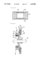
- FIG. 6 is a perspective view illustrating a shock-absorbing body mount 121
- FIG. 7 is a cross sectional view showing the body mount attached between a suspension frame and a body of a vehicle.
- the shock-absorbing body mount 121 is engaged with a joint 125 of a suspension frame 123 for wheels and fixed to a body 127 with a nut 129 and a bolt 131.
- the shock-absorbing body mount 121 includes separated outer plates 133A and 133B, an inner cylinder 135 of aluminum alloy, and a rubber 141 of vibration proof rubber.
- the rubber 141 adheres to the outer plates 133A and 133B and to the inner cylinder 135 by means of an inner adhesive layer 137 and an outer adhesive layer 139, respectively.
- the inner cylinder 135, the inner adhesive layer 137, and the rubber 141 form a bonded structure 142.
- the inner cylinder 135 of the bonded structure 142 is formed by extrusion molding of aluminum alloy of such composition as sample No. 6 in Table 1.
- the rubber 141 is formed by injection molding of natural rubber (NR).
- the inner adhesive layer 137 includes a lower-side coat of a phenol resin adhesive sold under the trademark Chemlok 205 by Lord, U.S., and an upper-side coat of a halogenated elastomer adhesive for rubber sold under the trademark Chemlok 220 by Lord, U.S.
- shock-absorbing body mount 121 thus constructed, vibration from the suspension frame 123 passes through the joint 125 and the outer plates 133A and 133B, is damped by the rubber 141, and is transmitted through the inner cylinder 135 to the body 127.
- the shock-absorbing body mount 121 of the embodiment absorbs the vibration.
- the outer plates 133A and 133B are prepared by pressing a steel plate and dividing the pressed plate into halves.
- the inner cylinder 135 is formed by extrusion molding and cutting of aluminum alloy.
- a lower-side adhesive coat and an upper-side adhesive coat are applied on the outer surface of the inner cylinder 135 and the inner surface of the outer plates 133A and 133B, respectively.
- the outer plates 133A and 133B and the inner cylinder 135 are then set in a mold (not shown). Natural rubber is injected into a cavity between the inner cylinder 135 and the outer plates 133A and 133B and heated at 160° C. for ten minutes to vulcanize, thus completing the shock-absorbing body mount 121.
- the adhesiveness of the shock-absorbing body mount 121 was tested under corrosive conditions. After the body mount 121 was subjected to the salt spray according to JIS Z2371 over 150 days, the bonded structure 142 of the body mount 121 was pulled with a universal tension tester. The rubber 141 was not peeled off but was fractured. These results showed that the bonded structure 142 maintained sufficient adhesiveness even under corrosive conditions.
- Use of aluminum alloy according to the present invention for the inner cylinder 135 decreases the total weight of the bonded structure 142 and improves adhesiveness under corrosive conditions.
Landscapes
- Engineering & Computer Science (AREA)
- General Engineering & Computer Science (AREA)
- Mechanical Engineering (AREA)
- Physics & Mathematics (AREA)
- Acoustics & Sound (AREA)
- Aviation & Aerospace Engineering (AREA)
- Vehicle Body Suspensions (AREA)
- Laminated Bodies (AREA)
Abstract
Description
y=-428+23.5/[Si]+30/[Cu]+0.075[Al].sup.2
______________________________________
Constituents     Amount (Parts by Weight
______________________________________
Natural rubber (NR)
                 100.
HAF carbon black 60.
Naphthene process oil
                 15.
Zinc oxide       5.
Paraffin wax     1.
Antioxidant 1    1.
Antioxidant 2    0.5
Vulcanization accelerator
                 1.
Sulfur           1.5
______________________________________
y=-428+23.5/[Si]+30/[Cu]+0.075[Al] (1)
                                  TABLE 1
__________________________________________________________________________
                 COMPOSITION OF aluminum alloy
SAMPLES No.
        PROCESS  Si Cu Fe Mn Mg Zn   Ni
__________________________________________________________________________
Examples
1       Die-casting
                 9.5
                    0.6
                       0.67
                          0.09
                             0.49
                                0.33 0.03
2       Die-casting
                 0.65
                    0.06
                       0.73
                          0.36
                             3.8
                                0.04 0.01
3       Casting  7.13
                    0.14
                       0.47
                          0.19
                             0.38
                                0.04 0.02
4       Casting  5.99
                    0.05
                       0.168
                          0.023
                             0.347
                                0.021
                                     0.018
5       Casting  4.99
                    2.15
                       0.166
                          0.026
                             0.093
                                0.007
                                     0.019
6       Extrusion
                 0.648
                    0.08
                       0.086
                          0.02
                             1.5
                                0.007
                                     0.002
7       Extrusion
                 0.079
                    0.173
                       0.085
                          0.02
                             1.5
                                0.5  0.008
Control examples
8       Die-casting
                 10.23
                    2.41
                       0.83
                          0.27
                             0.14
                                0.86 0.07
9       Casting  18.15
                    3.5
                       0.331
                          0.021
                             0.81
                                0.015
                                     0.025
        COMPOSITION          SALT SPRAY
SAMPLES No.
        Ti   Pb  Sn Cr V  Al RESULT (days)
__________________________________________________________________________
Examples
1       --   --  -- -- -- 88.29
                             100     Good
2       --   --  -- -- -- 94.35
                             600 or more
                                     Good
3       0.03 0.01
                 0.01
                    0.01
                       0.01
                          91.56
                             600     Good
4       0.1  0.004
                 0.002
                    0.04
                       -- 93.27
                             600     Good
5       0.108
             0.005
                 0.004
                    0.002
                       -- 92.43
                             175     Good
6       0.01 --  -- 0.002
                       0.007
                          97.63
                             600 or more
                                     Good
7       0.015
             --  -- 0.003
                       0.015
                          97.60
                             600 or more
                                     Good
Control examples
8       0.04 0.01
                 0.01
                    0.08
                       -- 85.05
                             70      No good
9       0.015
             0.007
                 0.008
                    0.006
                       -- 77.11
                             80      No good
__________________________________________________________________________
Claims (3)
y=-428+23.5/[Si]+30/[Cu]+0.075[Al].sup.2
Applications Claiming Priority (6)
| Application Number | Priority Date | Filing Date | Title |
|---|---|---|---|
| JP2-262772 | 1990-09-29 | ||
| JP2262770A JP2923025B2 (en) | 1990-09-29 | 1990-09-29 | Bonded structure of aluminum alloy member and rubber body and method of manufacturing the same |
| JP26277190A JPH04140533A (en) | 1990-09-29 | 1990-09-29 | Cushion type vehicle body holder and manufacture therefor |
| JP2-262771 | 1990-09-29 | ||
| JP26277290A JPH04140535A (en) | 1990-09-29 | 1990-09-29 | Disc type damper and manufacture therefor |
| JP2-262770 | 1990-09-29 |
Publications (1)
| Publication Number | Publication Date |
|---|---|
| US5279900A true US5279900A (en) | 1994-01-18 |
Family
ID=27335167
Family Applications (1)
| Application Number | Title | Priority Date | Filing Date |
|---|---|---|---|
| US07/766,395 Expired - Fee Related US5279900A (en) | 1990-09-29 | 1991-09-27 | Bonded structure of aluminum alloy and rubber and manufacture process therefor |
Country Status (1)
| Country | Link |
|---|---|
| US (1) | US5279900A (en) |
Cited By (12)
| Publication number | Priority date | Publication date | Assignee | Title |
|---|---|---|---|---|
| EP0667467A1 (en) * | 1994-02-10 | 1995-08-16 | Firma Carl Freudenberg | Method for producing a pressed-in torsional vibration damper |
| US5843264A (en) * | 1994-04-21 | 1998-12-01 | Toyoda Gosei Co., Ltd. | Vibration insulating assembly and method for making the same |
| GB2326457A (en) * | 1997-06-21 | 1998-12-23 | Perkins Ltd | Torsional vibration damper with attached thin walled pulley. |
| EP1079140A1 (en) * | 1999-08-27 | 2001-02-28 | Toyoda Gosei Co., Ltd. | Damper pulley |
| EP1164308A1 (en) * | 2000-06-16 | 2001-12-19 | Tokai Rubber Industries, Ltd. | Rubber product bonded to a metallic structure and method of producing the same |
| US6591434B1 (en) | 2002-02-04 | 2003-07-15 | Kohler Co. | Sound dampened sink |
| KR100836265B1 (en) * | 2008-01-03 | 2008-06-10 | 주식회사금강코엔 | Die casting aluminum alloy for fragility of portable electronics frame and method of manufacturing portable electronic frame using same |
| US20170050262A1 (en) * | 2015-08-20 | 2017-02-23 | Ultex Corporation | Bonding method and bonded structure |
| CN108754196A (en) * | 2018-08-30 | 2018-11-06 | 新疆众和股份有限公司 | A kind of preparation method of bonding acieral busbar |
| US20200208728A1 (en) * | 2017-02-24 | 2020-07-02 | Dayco Europe S.R.L. | Filtering pully |
| JP2021156618A (en) * | 2020-03-25 | 2021-10-07 | 住友精化株式会社 | Adhesive force prediction method of adhesive force improver of metal resin molding, and adhesive force improver |
| US11835106B2 (en) | 2017-12-15 | 2023-12-05 | Asml Netherlands B.V. | Method for manufacturing damper device, lithographic apparatus, projection system, and device manufacturing method |
Citations (1)
| Publication number | Priority date | Publication date | Assignee | Title |
|---|---|---|---|---|
| US5063098A (en) * | 1988-04-01 | 1991-11-05 | Nichias Corporation | Vibration damping materials and soundproofing structures using such damping materials |
-
1991
- 1991-09-27 US US07/766,395 patent/US5279900A/en not_active Expired - Fee Related
Patent Citations (1)
| Publication number | Priority date | Publication date | Assignee | Title |
|---|---|---|---|---|
| US5063098A (en) * | 1988-04-01 | 1991-11-05 | Nichias Corporation | Vibration damping materials and soundproofing structures using such damping materials |
Cited By (16)
| Publication number | Priority date | Publication date | Assignee | Title |
|---|---|---|---|---|
| EP0667467A1 (en) * | 1994-02-10 | 1995-08-16 | Firma Carl Freudenberg | Method for producing a pressed-in torsional vibration damper |
| US6136134A (en) * | 1994-02-10 | 2000-10-24 | Hans-Werner Schwerdt | Process for manufacturing a pressed-in torsional vibration damper |
| US5843264A (en) * | 1994-04-21 | 1998-12-01 | Toyoda Gosei Co., Ltd. | Vibration insulating assembly and method for making the same |
| GB2326457A (en) * | 1997-06-21 | 1998-12-23 | Perkins Ltd | Torsional vibration damper with attached thin walled pulley. |
| EP1079140A1 (en) * | 1999-08-27 | 2001-02-28 | Toyoda Gosei Co., Ltd. | Damper pulley |
| EP1164308A1 (en) * | 2000-06-16 | 2001-12-19 | Tokai Rubber Industries, Ltd. | Rubber product bonded to a metallic structure and method of producing the same |
| US6656582B2 (en) | 2000-06-16 | 2003-12-02 | Tokai Rubber Industries, Ltd. | Rubber product with metallic structure and method of producing the same |
| US6591434B1 (en) | 2002-02-04 | 2003-07-15 | Kohler Co. | Sound dampened sink |
| KR100836265B1 (en) * | 2008-01-03 | 2008-06-10 | 주식회사금강코엔 | Die casting aluminum alloy for fragility of portable electronics frame and method of manufacturing portable electronic frame using same |
| US20170050262A1 (en) * | 2015-08-20 | 2017-02-23 | Ultex Corporation | Bonding method and bonded structure |
| US10052713B2 (en) * | 2015-08-20 | 2018-08-21 | Ultex Corporation | Bonding method and bonded structure |
| US20200208728A1 (en) * | 2017-02-24 | 2020-07-02 | Dayco Europe S.R.L. | Filtering pully |
| US11815172B2 (en) * | 2017-02-24 | 2023-11-14 | Dayco Europe S.R.L. | Filtering pulley |
| US11835106B2 (en) | 2017-12-15 | 2023-12-05 | Asml Netherlands B.V. | Method for manufacturing damper device, lithographic apparatus, projection system, and device manufacturing method |
| CN108754196A (en) * | 2018-08-30 | 2018-11-06 | 新疆众和股份有限公司 | A kind of preparation method of bonding acieral busbar |
| JP2021156618A (en) * | 2020-03-25 | 2021-10-07 | 住友精化株式会社 | Adhesive force prediction method of adhesive force improver of metal resin molding, and adhesive force improver |
Similar Documents
| Publication | Publication Date | Title |
|---|---|---|
| US4806437A (en) | Vibration isolating mount | |
| US5279900A (en) | Bonded structure of aluminum alloy and rubber and manufacture process therefor | |
| US9327482B2 (en) | Bonded part with laminated rubber member and method of making | |
| JP3936293B2 (en) | Method for directly bonding rubber and at least one second substrate and article obtained by said method | |
| US6984432B2 (en) | Damper and process thereof | |
| US6345430B1 (en) | Damper | |
| EP1193418B1 (en) | Vibration damper including polyamide-resin member covered by elastic layer, and method of producing the same | |
| US6292995B1 (en) | Powder coating as substrate for epoxy bonding of vibration isolation mounts | |
| US4342810A (en) | Plastic core composite having improved impact resistance | |
| US20070089949A1 (en) | Vibration damping rubber member and method of producing the same | |
| US6022626A (en) | Coatings for high temperature engine mounts | |
| JPH04140535A (en) | Disc type damper and manufacture therefor | |
| JPH04140533A (en) | Cushion type vehicle body holder and manufacture therefor | |
| JP2003148537A (en) | Anti-vibration rubber member for automobile and manufacturing method thereof | |
| JP3620712B2 (en) | Manufacturing method of vulcanized rubber products with excellent fuel oil resistance | |
| JP2003148536A (en) | Anti-vibration rubber member for automobile and manufacturing method thereof | |
| JP3240891B2 (en) | Anti-vibration device | |
| JPH01144485A (en) | Torsional damper | |
| JP2923025B2 (en) | Bonded structure of aluminum alloy member and rubber body and method of manufacturing the same | |
| JPS6260434B2 (en) | ||
| JP2007118292A (en) | Anti-vibration rubber material | |
| JP2004027068A (en) | The vulcanization bonding method of rubber and metal | |
| JP6519286B2 (en) | Rubber-metal laminated structure and method for manufacturing the same | |
| JP2001108021A (en) | Power transmission belt and method of manufacturing the same | |
| JPS63238183A (en) | Primer for metal |
Legal Events
| Date | Code | Title | Description |
|---|---|---|---|
| AS | Assignment |
Owner name: TOYODA GOSEI CO., LTD., JAPAN Free format text: ASSIGNMENT OF ASSIGNORS INTEREST.;ASSIGNORS:TAKEUCHI, KATSUMASA;YOKOI, HIROSHI;IMAI, HIDEYUKI;REEL/FRAME:005859/0891 Effective date: 19910919 |
|
| FEPP | Fee payment procedure |
Free format text: PAYOR NUMBER ASSIGNED (ORIGINAL EVENT CODE: ASPN); ENTITY STATUS OF PATENT OWNER: LARGE ENTITY |
|
| FPAY | Fee payment |
Year of fee payment: 4 |
|
| FPAY | Fee payment |
Year of fee payment: 8 |
|
| AS | Assignment |
Owner name: TOYO TIRE & RUBBER CO., LTD., JAPAN Free format text: ASSIGNMENT OF ASSIGNORS INTEREST;ASSIGNOR:TOYODA GOSEI CO., LTD.;REEL/FRAME:013280/0501 Effective date: 20020401 |
|
| REMI | Maintenance fee reminder mailed | ||
| LAPS | Lapse for failure to pay maintenance fees | ||
| STCH | Information on status: patent discontinuation |
Free format text: PATENT EXPIRED DUE TO NONPAYMENT OF MAINTENANCE FEES UNDER 37 CFR 1.362 |
|
| FP | Lapsed due to failure to pay maintenance fee |
Effective date: 20060118 |