US5275033A - Metal can body shaping installation - Google Patents
Metal can body shaping installation Download PDFInfo
- Publication number
- US5275033A US5275033A US07/977,798 US97779892A US5275033A US 5275033 A US5275033 A US 5275033A US 97779892 A US97779892 A US 97779892A US 5275033 A US5275033 A US 5275033A
- Authority
- US
- United States
- Prior art keywords
- station
- die
- installation according
- shaping
- pressurized fluid
- Prior art date
- Legal status (The legal status is an assumption and is not a legal conclusion. Google has not performed a legal analysis and makes no representation as to the accuracy of the status listed.)
- Expired - Fee Related
Links
Images


Classifications
-
- B—PERFORMING OPERATIONS; TRANSPORTING
- B21—MECHANICAL METAL-WORKING WITHOUT ESSENTIALLY REMOVING MATERIAL; PUNCHING METAL
- B21D—WORKING OR PROCESSING OF SHEET METAL OR METAL TUBES, RODS OR PROFILES WITHOUT ESSENTIALLY REMOVING MATERIAL; PUNCHING METAL
- B21D26/00—Shaping without cutting otherwise than using rigid devices or tools or yieldable or resilient pads, i.e. applying fluid pressure or magnetic forces
- B21D26/02—Shaping without cutting otherwise than using rigid devices or tools or yieldable or resilient pads, i.e. applying fluid pressure or magnetic forces by applying fluid pressure
- B21D26/033—Deforming tubular bodies
- B21D26/049—Deforming bodies having a closed end
-
- B—PERFORMING OPERATIONS; TRANSPORTING
- B21—MECHANICAL METAL-WORKING WITHOUT ESSENTIALLY REMOVING MATERIAL; PUNCHING METAL
- B21D—WORKING OR PROCESSING OF SHEET METAL OR METAL TUBES, RODS OR PROFILES WITHOUT ESSENTIALLY REMOVING MATERIAL; PUNCHING METAL
- B21D51/00—Making hollow objects
- B21D51/16—Making hollow objects characterised by the use of the objects
- B21D51/26—Making hollow objects characterised by the use of the objects cans or tins; Closing same in a permanent manner
-
- B—PERFORMING OPERATIONS; TRANSPORTING
- B65—CONVEYING; PACKING; STORING; HANDLING THIN OR FILAMENTARY MATERIAL
- B65D—CONTAINERS FOR STORAGE OR TRANSPORT OF ARTICLES OR MATERIALS, e.g. BAGS, BARRELS, BOTTLES, BOXES, CANS, CARTONS, CRATES, DRUMS, JARS, TANKS, HOPPERS, FORWARDING CONTAINERS; ACCESSORIES, CLOSURES, OR FITTINGS THEREFOR; PACKAGING ELEMENTS; PACKAGES
- B65D83/00—Containers or packages with special means for dispensing contents
- B65D83/14—Containers or packages with special means for dispensing contents for delivery of liquid or semi-liquid contents by internal gaseous pressure, i.e. aerosol containers comprising propellant for a product delivered by a propellant
- B65D83/38—Details of the container body
Definitions
- the invention concerns a method of cold shaping a metal can body and a can body shaping installation adapted to implement it.
- One prior art can shaping method is usually applied to can bodies assembled from at least two components, typically a tubular part and a bottom crimped to one end thereof.
- the tubular part may be a cylinder of circular, rectangular or square cross-section.
- This method uses a mechanism forming a core adapted to be inserted axially inside the can body through the opening thereof and having sectors adapted to be moved apart in the radially outward direction until they contact the inside wall of the can body to be shaped.
- the deforming means and the actuating system thereof are essentially mechanical.
- Cans shaped in this way have shortcomings in respect of their appearance which are inherent to the shaping system itself.
- the imprints of the various sectors are visible on the can body walls. This means that the latter cannot have a perfectly regular surface. These imprints may even cause scoring of the varnish and lead eventually to corrosion. They may also lead to rupturing of the can. Additionally, the mechanism is complex and costly.
- the invention proposes a simpler and more effective new method enabling the surface state and the general appearance of the shaped can body to be significantly improved and high rates of throughput to be achieved in production.
- the present invention consists in a method of shaping a metal can body by filling said can body at least partially with a liquid so as to leave only a residual volume adjoining an opening at the upper end of said can body, inserting said can body in a die having substantially the shape to be imparted to said can body, applying pressure in said residual volume so that said can body is deformed into contact with said die and extracting said can body from said die.
- the shaped can body On leaving the die the shaped can body is usually emptied of the liquid that it contains and transferred to an oven or like drying means.
- the liquid may be water.
- this shaping phase can be used to apply a protective internal coating to the walls of the can body. All that is required is to add to the liquid a protective agent adapted to leave a protective film on said walls after the can body is emptied and dried.
- an axial force may be applied to the can body while pressure is applied to said residual volume to favor the "movement" of the metal which is pressed against the inside walls of the die. This avoids exaggerated thinning of the metal in certain critical deformation areas.
- the invention consists in an installation for shaping metal can bodies essentially comprising a station for filling at least one can body provided with means for introducing a required quantity of liquid into said at least one can body, a shaping station on the downstream side of said filling station comprising at least one die adapted to receive a can body and shaped internally according to the required shape to be imparted to said can body and a connector adapted to be sealed to the opening of said can body and connected to a pressurized fluid supply.
- the conveyor which extends from the filling station to the shaping station, may advantageously comprise bases each having a shape adapted to receive a can body.
- Each base is inserted into the lower part of the die which to this end comprises two lateral half-shells which are adapted to be moved apart and then closed onto a can body filled with liquid and on the point of being shaped in the manner indicated hereinabove.
- the aforementioned connector may advantageously comprise an axially sliding plug shaped to provide a sealed fit to the opening of the can body trapped in the die. The plug is loaded during the can body shaping phase to apply thereto the axial force mentioned above.
- FIG. 1 is a diagrammatic general view of the installation.
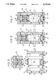
- FIG. 2 is a more detailed diagrammatic view in cross-section on the line II--II in FIG. 1.
- FIG. 3 is a top view of FIG. 2.
- FIG. 4 is a diagrammatic view of the can body orienting device.
- FIG. 5 is a diagrammatic view of the various parts of a die about to be closed on a can body.
- FIG. 6 is a view similar to FIG. 5 showing the die enclosing a can body which is about to be shaped.
- FIG. 7 is a view similar to FIG. 6 showing the same items after said can body is shaped.
- the installation shown in the drawings comprises in succession a feed conveyor 11 onto which are placed the can bodies to be shaped, a main conveyor 12 along which the main processing stations are arranged, a transfer conveyor 13 and a drying oven 14.
- the transfer conveyor 13 is installed between the outlet of the main conveyor 12 and the outlet of the oven 14.
- a sequentially operated feed carousel 16 is installed between the feed conveyor and the main conveyor.
- a similar offtake carousel 18 is installed between the main conveyor and the transfer conveyor. All the components described so far are known in themselves.
- the main conveyor is provided with bases 20 each of which has a shape adapted to receive a can body.
- the feed carousel and main conveyor drive means are synchronized so that each can body 21 taken up by said feed carousel is put down on a base.
- the bases 20 are made from a magnetic material which facilitates the placing of steel can bodies.
- synchronization is achieved by virtue of the fact that the feed carousel 16 and the main conveyor 12 are driven by a common motor 22 via a gearbox 24 comprising two perpendicular output shafts, a shaft 25 driving the carousel and a shaft 26 driving a drive wheel 27 of said main conveyor.
- the can bodies 21 are adapted to contain products to be sprayed in aerosol form.
- a can body of this kind conventionally comprises a circular cross-section cylinder 26, a bottom 27 crimped to this cylinder and a cap 28 crimped to the upper part of the cylinder and adapted to receive a sprayer device.
- To customize the packaging a particular shape is imparted to the can body, specifically by modifying the shape of the cylinder.
- this is merely one example of application of the general principle of the invention, which can be adapted to impart any required shape to any type of can body.
- the filling station comprises a manifold 36 connected to a liquid supply tank 38 adapted to feed four can bodies simultaneously and the shaping station is equipped with four dies 34.
- the filling station includes means for introducing a required quantity of liquid such as water for example into each can body.
- Each die 34 is shaped internally according to the final shape to be imparted to the can body.
- Each die has a connector 40 which can make a sealed fit to the opening of the can body and this connector is connected to a pressurized fluid supply 42.
- the fluid may be a liquid or even air.
- the four connectors 40 are fastened to a common vertically mobile unit 41 and connected to the pressurized fluid supply 42.
- the liquid 43 fed into the can bodies at the filling station 30 is usually water but this liquid may have added to it a protective agent adapted to form a coating on the inside walls of the can body after it is emptied and dried.
- the quantity of liquid 43 fed into each can body at the filling station is determined according to the can body type so that there remains only a relatively small residual volume 44 adjoining the opening at the top of the can body.
- Each base 20 can pivot about a main axis of symmetry coincident with that of the can body just placed on said base.
- a can body orienting station 46 here combined with the filling station, in other words it is on the downstream side of the shaping station.
- This orienting station comprises means for turning the base to bring the can body into a predetermined position as shown in FIG. 4.
- each base 20 rotates on a ball bearing 47 and is coupled during filling to a stepper motor 48 controlled by an electronic unit 49 connected to a sensor 50 facing the can body.
- This sensor is responsive to a particular feature of the can body, a longitudinal seam weld 51 in this example.
- the electronic unit operates the motor 48 until said weld is in an accurately determined position defined by the location of the sensor 50.
- the weld enables the weld to be positioned so that, if it has any significant additional thickness, this can be caused to coincide with a longitudinal groove in the die.
- this orienting can serve to position decor silkscreened onto the surface of the can body relative to a particular feature in relief resulting from the shaping operation.
- the can body orienting means could be different than those shown and consist, for example, in a mechanism adapted to reorient each can body mounted on a non-pivoting base.
- each die comprises two lateral half-shells 55a, 55b operated by horizontal jacks (not shown).
- the two half-shells are adapted to move away from each other. At their lower ends they have semi-circular recesses 56. These recesses are shaped so that said half-shells can fit around a base as mentioned above.
- the base 20 of the main conveyor constitutes the bottom of the die.
- Each connector 40 fits to an opening at the top of the die so that pressurized fluid can be injected into the residual space above the liquid filling the can body to deform said body until it contacts the inside wall of the die 34, producing the required shape.
- Vent holes 48 are provided in the wall of one half-shell to enable escape of air trapped between the die and the can body during this shaping phase.
- each connector 40 comprises an axially slidable plug 60 having an application side 62 adapted to fit in a sealed manner to the opening of the can body trapped in the die.
- this application side has a shape substantially reproducing the outline of the cap so that said sliding plug 60 is applied to substantially all of the surface of the can body cap.
- the plug includes a bore to enable pressurized fluid to be introduced.
- the connector further comprises means for forcibly applying the plug to the can body opening.
- the connector comprises a pressure chamber 64 with a mobile wall at least part of which is formed by the upper side of the sliding plug, opposite the application side thereof.
- the pressure chamber communicates with a pressurized fluid supply which in this example is the pressurized fluid supply 42 for shaping the can body.
- the pressure chamber 64 is coaxial with the pressurized fluid inlet pipe 65 and communicates with it.
- a flexible fluid-tight membrane 66 made from an elastomer material in this example, is interleaved into said pressure chamber to separate the sliding plug 60 from fluid admitted into the chamber.
- the situation is that shown in FIG. 7.
- the mobile parts of the die are again moved to release the four shaped can bodies, which are then moved onto the transfer conveyor by the offtake carousel 18.
- the shaped can bodies pass through an emptying station 68 which is known in itself and which manipulates the can bodies to tip out the liquid that they contain.
- This liquid is recovered in a tank 69 and if appropriate recycled to the filling means (to be more precise to the tank 38), especially if it contains a protective agent.
- the can bodies are empty they are passed through the drying oven 14 before they are transferred to other processing stations.
Abstract
Description
Claims (12)
Applications Claiming Priority (2)
| Application Number | Priority Date | Filing Date | Title |
|---|---|---|---|
| FR9114213 | 1991-11-19 | ||
| FR9114213A FR2683750B1 (en) | 1991-11-19 | 1991-11-19 | METHOD FOR CONFORMING A METAL BOX BODY AND INSTALLATION FOR CONFORMING SUCH A BOX BODY. |
Publications (1)
| Publication Number | Publication Date |
|---|---|
| US5275033A true US5275033A (en) | 1994-01-04 |
Family
ID=9419076
Family Applications (1)
| Application Number | Title | Priority Date | Filing Date |
|---|---|---|---|
| US07/977,798 Expired - Fee Related US5275033A (en) | 1991-11-19 | 1992-11-17 | Metal can body shaping installation |
Country Status (6)
| Country | Link |
|---|---|
| US (1) | US5275033A (en) |
| EP (1) | EP0543695B1 (en) |
| DE (1) | DE69219439T2 (en) |
| ES (1) | ES2101064T3 (en) |
| FR (1) | FR2683750B1 (en) |
| GR (1) | GR3024221T3 (en) |
Cited By (16)
| Publication number | Priority date | Publication date | Assignee | Title |
|---|---|---|---|---|
| US5687599A (en) * | 1996-01-04 | 1997-11-18 | Reynolds Metals Company | Method of forming a can with an electromagnetically formed contoured sidewall and necked end |
| US5691582A (en) * | 1993-03-23 | 1997-11-25 | Coors Brewing Company | Can body maker with linear motor redraw actuator |
| US5794474A (en) * | 1997-01-03 | 1998-08-18 | Ball Corporation | Method and apparatus for reshaping a container body |
| EP0874701A1 (en) * | 1996-01-04 | 1998-11-04 | Ball Corporation | Method and apparatus for shaping a container |
| US6079244A (en) * | 1996-01-04 | 2000-06-27 | Ball Corporation | Method and apparatus for reshaping a container body |
| EP1034860A2 (en) * | 1995-07-25 | 2000-09-13 | Dispensing Containers Corporation | Method and apparatus for making a thin walled cover for an aerosol container |
| US6151939A (en) * | 1996-01-04 | 2000-11-28 | Delaware Capital Formation, Inc. | Can shaping apparatus |
| US6253597B1 (en) * | 1988-02-19 | 2001-07-03 | Corus Staal B.V. | Body-necking a wall-ironed can |
| NL1014268C2 (en) * | 2000-02-02 | 2001-08-03 | Corus Staal Bv | Thin-walled metal tube has temporary closures at each end whilst fluid overpressure applied internally causes plastic deformation against surrounding mould |
| US6338189B1 (en) | 1999-10-07 | 2002-01-15 | Allison Engine Company, Inc. | Method and apparatus for expansion forming a workpiece using an external deformable supporting fixture |
| US6557693B1 (en) * | 1998-06-05 | 2003-05-06 | Knapp Logistik Automation Gmbh | Conveyor section arrangement for containers being filled with items or bulk material at a filling station |
| US20050109422A1 (en) * | 2003-11-25 | 2005-05-26 | General Mills, Inc. | Apparatus and method for transporting containers within a packaging system |
| US20070131518A1 (en) * | 2005-12-12 | 2007-06-14 | Hoon Son | Apparatus for changing position of and carrying wheel |
| WO2014153545A1 (en) * | 2013-03-21 | 2014-09-25 | Dayton Systems Group, Inc. | Hydroformed can bottom expansion process and apparatus |
| JP2018517569A (en) * | 2015-05-26 | 2018-07-05 | ノベリス・インコーポレイテッドNovelis Inc. | High speed blow molding process for forming aluminum containers using 3XXX alloys with high recycle content |
| US11335486B2 (en) | 2014-05-04 | 2022-05-17 | Belvac Production Machinery Inc. | Systems and methods for electromagnetic forming of containers |
Families Citing this family (10)
| Publication number | Priority date | Publication date | Assignee | Title |
|---|---|---|---|---|
| US5899104A (en) * | 1995-02-16 | 1999-05-04 | Thomassen & Drijver-Verblifa B.V. | Method and apparatus for shaping a can |
| FR2731927B1 (en) * | 1995-03-21 | 1997-06-13 | Lorraine Laminage | PROCESS FOR MANUFACTURING A SHAPED METAL BOX |
| FR2731929B1 (en) * | 1995-03-21 | 1997-06-13 | Lorraine Laminage | PROCESS FOR MANUFACTURING A SHAPED METAL BOX |
| US5746080A (en) * | 1995-10-02 | 1998-05-05 | Crown Cork & Seal Company, Inc. | Systems and methods for making decorative shaped metal cans |
| US5832766A (en) * | 1996-07-15 | 1998-11-10 | Crown Cork & Seal Technologies Corporation | Systems and methods for making decorative shaped metal cans |
| US5829290A (en) * | 1996-02-14 | 1998-11-03 | Crown Cork & Seal Technologies Corporation | Reshaping of containers |
| US5938389A (en) * | 1996-08-02 | 1999-08-17 | Crown Cork & Seal Technologies Corporation | Metal can and method of making |
| EP2366472A1 (en) * | 2010-02-23 | 2011-09-21 | Impress Group B.V. | Metal precontainer, a blow formed metal container |
| DK2359953T3 (en) * | 2010-02-23 | 2017-11-20 | Ardagh Mp Group Netherlands Bv | Process for blow molding a pre-container to produce a blow molded metal container |
| DE102013114007A1 (en) * | 2013-12-13 | 2015-06-18 | Ball Europe Gmbh | Process for the pretreatment of a can body made from a metal sheet |
Citations (13)
| Publication number | Priority date | Publication date | Assignee | Title |
|---|---|---|---|---|
| US2972971A (en) * | 1955-07-18 | 1961-02-28 | Hillgren Mfg Company | Method of drawing door knobs |
| GB982808A (en) * | 1962-02-28 | 1965-02-10 | Gerzat Metallurg | Shaping method and apparatus |
| US3220235A (en) * | 1961-09-19 | 1965-11-30 | Nat Lock Co | Method and apparatus for making bulged articles |
| US3576247A (en) * | 1969-06-18 | 1971-04-27 | Canadian Stackpole Ltd | Apparatus for orienting containers |
| US3580380A (en) * | 1968-09-11 | 1971-05-25 | Reynolds Metals Co | Method of and apparatus for orienting indicia bearing cylindrical objects |
| US3807209A (en) * | 1972-01-28 | 1974-04-30 | Continental Can Co | Can body shaper |
| US3857265A (en) * | 1968-08-02 | 1974-12-31 | Continental Can Co | Apparatus for electrohydraulically forming tubular elements |
| US4110493A (en) * | 1975-10-06 | 1978-08-29 | Gerber Products Company | System and method for coating container seams |
| US4143754A (en) * | 1977-07-07 | 1979-03-13 | Morgan Fairest Limited | Labelling machines with article guide plate |
| DE3716176A1 (en) * | 1987-05-14 | 1988-09-08 | Praezisions Werkzeuge Ag | Method and device for reshaping hollow bodies, and use of the method or the device and can body |
| EP0349337A2 (en) * | 1988-07-01 | 1990-01-03 | Weirton Steel Corporation | Transfer of can bodies in can body line |
| GB2224965A (en) * | 1988-08-31 | 1990-05-23 | Metal Box Plc | Methods and apparatus for reshaping hollow members |
| US5058724A (en) * | 1990-11-08 | 1991-10-22 | Hinton Gaylen R | Apparatus and method for orienting articles and containers |
-
1991
- 1991-11-19 FR FR9114213A patent/FR2683750B1/en not_active Expired - Fee Related
-
1992
- 1992-11-03 ES ES92402965T patent/ES2101064T3/en not_active Expired - Lifetime
- 1992-11-03 DE DE69219439T patent/DE69219439T2/en not_active Expired - Fee Related
- 1992-11-03 EP EP92402965A patent/EP0543695B1/en not_active Expired - Lifetime
- 1992-11-17 US US07/977,798 patent/US5275033A/en not_active Expired - Fee Related
-
1997
- 1997-07-23 GR GR970401867T patent/GR3024221T3/en unknown
Patent Citations (14)
| Publication number | Priority date | Publication date | Assignee | Title |
|---|---|---|---|---|
| US2972971A (en) * | 1955-07-18 | 1961-02-28 | Hillgren Mfg Company | Method of drawing door knobs |
| US3220235A (en) * | 1961-09-19 | 1965-11-30 | Nat Lock Co | Method and apparatus for making bulged articles |
| GB982808A (en) * | 1962-02-28 | 1965-02-10 | Gerzat Metallurg | Shaping method and apparatus |
| US3857265A (en) * | 1968-08-02 | 1974-12-31 | Continental Can Co | Apparatus for electrohydraulically forming tubular elements |
| US3580380A (en) * | 1968-09-11 | 1971-05-25 | Reynolds Metals Co | Method of and apparatus for orienting indicia bearing cylindrical objects |
| US3576247A (en) * | 1969-06-18 | 1971-04-27 | Canadian Stackpole Ltd | Apparatus for orienting containers |
| US3807209A (en) * | 1972-01-28 | 1974-04-30 | Continental Can Co | Can body shaper |
| US4110493A (en) * | 1975-10-06 | 1978-08-29 | Gerber Products Company | System and method for coating container seams |
| US4143754A (en) * | 1977-07-07 | 1979-03-13 | Morgan Fairest Limited | Labelling machines with article guide plate |
| DE3716176A1 (en) * | 1987-05-14 | 1988-09-08 | Praezisions Werkzeuge Ag | Method and device for reshaping hollow bodies, and use of the method or the device and can body |
| EP0349337A2 (en) * | 1988-07-01 | 1990-01-03 | Weirton Steel Corporation | Transfer of can bodies in can body line |
| US4974439A (en) * | 1988-07-01 | 1990-12-04 | Saunders William T | Controlled transfer of sheet metal can bodies in can body line |
| GB2224965A (en) * | 1988-08-31 | 1990-05-23 | Metal Box Plc | Methods and apparatus for reshaping hollow members |
| US5058724A (en) * | 1990-11-08 | 1991-10-22 | Hinton Gaylen R | Apparatus and method for orienting articles and containers |
Cited By (23)
| Publication number | Priority date | Publication date | Assignee | Title |
|---|---|---|---|---|
| US6253597B1 (en) * | 1988-02-19 | 2001-07-03 | Corus Staal B.V. | Body-necking a wall-ironed can |
| US5691582A (en) * | 1993-03-23 | 1997-11-25 | Coors Brewing Company | Can body maker with linear motor redraw actuator |
| EP1034860A2 (en) * | 1995-07-25 | 2000-09-13 | Dispensing Containers Corporation | Method and apparatus for making a thin walled cover for an aerosol container |
| EP1034860A3 (en) * | 1995-07-25 | 2000-09-20 | Dispensing Containers Corporation | Method and apparatus for making a thin walled cover for an aerosol container |
| US5916317A (en) * | 1996-01-04 | 1999-06-29 | Ball Corporation | Metal container body shaping/embossing |
| US6343496B1 (en) * | 1996-01-04 | 2002-02-05 | Delaware Capital Formation, Ltd. | Can shaping apparatus and method |
| US6079244A (en) * | 1996-01-04 | 2000-06-27 | Ball Corporation | Method and apparatus for reshaping a container body |
| EP0874701A4 (en) * | 1996-01-04 | 1999-03-03 | Ball Corp | Method and apparatus for shaping a container |
| EP0874701A1 (en) * | 1996-01-04 | 1998-11-04 | Ball Corporation | Method and apparatus for shaping a container |
| US6151939A (en) * | 1996-01-04 | 2000-11-28 | Delaware Capital Formation, Inc. | Can shaping apparatus |
| US5687599A (en) * | 1996-01-04 | 1997-11-18 | Reynolds Metals Company | Method of forming a can with an electromagnetically formed contoured sidewall and necked end |
| US5794474A (en) * | 1997-01-03 | 1998-08-18 | Ball Corporation | Method and apparatus for reshaping a container body |
| US6557693B1 (en) * | 1998-06-05 | 2003-05-06 | Knapp Logistik Automation Gmbh | Conveyor section arrangement for containers being filled with items or bulk material at a filling station |
| US6338189B1 (en) | 1999-10-07 | 2002-01-15 | Allison Engine Company, Inc. | Method and apparatus for expansion forming a workpiece using an external deformable supporting fixture |
| NL1014268C2 (en) * | 2000-02-02 | 2001-08-03 | Corus Staal Bv | Thin-walled metal tube has temporary closures at each end whilst fluid overpressure applied internally causes plastic deformation against surrounding mould |
| US20050109422A1 (en) * | 2003-11-25 | 2005-05-26 | General Mills, Inc. | Apparatus and method for transporting containers within a packaging system |
| US7207359B2 (en) * | 2003-11-25 | 2007-04-24 | General Mills, Inc. | Apparatus and method for transporting containers within a packaging system |
| US20070131518A1 (en) * | 2005-12-12 | 2007-06-14 | Hoon Son | Apparatus for changing position of and carrying wheel |
| WO2014153545A1 (en) * | 2013-03-21 | 2014-09-25 | Dayton Systems Group, Inc. | Hydroformed can bottom expansion process and apparatus |
| WO2016036855A1 (en) * | 2013-03-21 | 2016-03-10 | Dayton Systems Group, Inc. | Hydroformed bottom expansion process and apparatus |
| US11335486B2 (en) | 2014-05-04 | 2022-05-17 | Belvac Production Machinery Inc. | Systems and methods for electromagnetic forming of containers |
| US11596994B2 (en) | 2014-05-04 | 2023-03-07 | Belvac Production Machinery, Inc. | Systems and methods for electromagnetic forming of containers |
| JP2018517569A (en) * | 2015-05-26 | 2018-07-05 | ノベリス・インコーポレイテッドNovelis Inc. | High speed blow molding process for forming aluminum containers using 3XXX alloys with high recycle content |
Also Published As
| Publication number | Publication date |
|---|---|
| EP0543695B1 (en) | 1997-05-02 |
| EP0543695A1 (en) | 1993-05-26 |
| DE69219439T2 (en) | 1997-11-13 |
| FR2683750A1 (en) | 1993-05-21 |
| FR2683750B1 (en) | 1995-09-01 |
| GR3024221T3 (en) | 1997-10-31 |
| DE69219439D1 (en) | 1997-06-05 |
| ES2101064T3 (en) | 1997-07-01 |
Similar Documents
| Publication | Publication Date | Title |
|---|---|---|
| US5275033A (en) | Metal can body shaping installation | |
| FI94845C (en) | Method for making a two-chamber pressure pack | |
| CA2233642A1 (en) | Systems and methods for making decorative shaped metal cans | |
| US4272977A (en) | Method and apparatus for necking-in and flanging a container body | |
| US5676512A (en) | Thin walled cover for aerosol container and method of making same | |
| US5799525A (en) | Tooling and method for the embossing of a container and the resulting container | |
| CA2071799A1 (en) | Apparatus and method for reshaping containers | |
| KR20140110034A (en) | System and method for forming a metal beverage container using blow molding | |
| CA2580821A1 (en) | Dry hydraulic can shaping | |
| AU617566B2 (en) | Method and apparatus for embossing the inside surface of a cup-shaped article | |
| US5687599A (en) | Method of forming a can with an electromagnetically formed contoured sidewall and necked end | |
| US7568369B2 (en) | Mold construction for a process and apparatus for manufacturing shaped containers | |
| JPH0464763B2 (en) | ||
| US4856176A (en) | Process and apparatus for assembling a tubular container | |
| US3461195A (en) | Spraying method and apparatus to lubricate punch surfaces of tabletting machines | |
| US4263251A (en) | Method and apparatus for producing one-piece capsules | |
| US5657833A (en) | Self-contained unitized lubricant delivery apparatus | |
| CN101905767A (en) | Method for manufacturing package bucket | |
| CN207171432U (en) | A kind of engine valve lock clamp automatic press mounting frock | |
| JP4773590B1 (en) | Double aerosol container manufacturing method, double aerosol container, and double aerosol container manufacturing apparatus. | |
| US697786A (en) | Combined bottomer and crimper for can-bodies. | |
| WO1999037420A1 (en) | Process for producing a metal can with an insert piece for packaging, for example, a foodstuff, and a can of this nature | |
| CN105682901B (en) | Apparatus and method for compressing plastic containers and stress-whitening can be prevented | |
| CN107505092A (en) | One kind tank tank bottom can body junction sealing safety detection device | |
| JPH01258826A (en) | Lining method for pipe inner face |
Legal Events
| Date | Code | Title | Description |
|---|---|---|---|
| AS | Assignment |
Owner name: CARNAUDMETALBOX (FORMERLY CALLED CMB PACKAGING S.A Free format text: ASSIGNMENT OF ASSIGNORS INTEREST.;ASSIGNOR:RIVIERE, MAURICE;REEL/FRAME:006341/0131 Effective date: 19911021 |
|
| FEPP | Fee payment procedure |
Free format text: PAYOR NUMBER ASSIGNED (ORIGINAL EVENT CODE: ASPN); ENTITY STATUS OF PATENT OWNER: LARGE ENTITY |
|
| FPAY | Fee payment |
Year of fee payment: 4 |
|
| AS | Assignment |
Owner name: CHASE MANHATTAN BANK, AS COLLATERAL AGENT, THE, NEW YORK Free format text: SECURITY INTEREST;ASSIGNOR:CROWN CORK & SEAL TECHNOLOGIES CORPORATION;REEL/FRAME:011667/0001 Effective date: 20010302 Owner name: CHASE MANHATTAN BANK, AS COLLATERAL AGENT, THE, NE Free format text: SECURITY INTEREST;ASSIGNOR:CROWN CORK & SEAL TECHNOLOGIES CORPORATION;REEL/FRAME:011667/0001 Effective date: 20010302 |
|
| REMI | Maintenance fee reminder mailed | ||
| LAPS | Lapse for failure to pay maintenance fees | ||
| STCH | Information on status: patent discontinuation |
Free format text: PATENT EXPIRED DUE TO NONPAYMENT OF MAINTENANCE FEES UNDER 37 CFR 1.362 |
|
| FP | Lapsed due to failure to pay maintenance fee |
Effective date: 20020104 |