US5272644A - Apparatus for controlling a heating temperature - Google Patents
Apparatus for controlling a heating temperature Download PDFInfo
- Publication number
- US5272644A US5272644A US07/612,436 US61243690A US5272644A US 5272644 A US5272644 A US 5272644A US 61243690 A US61243690 A US 61243690A US 5272644 A US5272644 A US 5272644A
- Authority
- US
- United States
- Prior art keywords
- temperature
- heating
- control
- heater
- barrel
- Prior art date
- Legal status (The legal status is an assumption and is not a legal conclusion. Google has not performed a legal analysis and makes no representation as to the accuracy of the status listed.)
- Expired - Lifetime
Links
- 238000010438 heat treatment Methods 0.000 title claims abstract description 54
- 239000011347 resin Substances 0.000 claims abstract description 18
- 229920005989 resin Polymers 0.000 claims abstract description 18
- 230000004044 response Effects 0.000 claims abstract description 16
- 230000006870 function Effects 0.000 claims description 15
- 230000008859 change Effects 0.000 claims description 10
- 230000001447 compensatory effect Effects 0.000 claims description 9
- 230000000694 effects Effects 0.000 claims description 4
- 238000002347 injection Methods 0.000 abstract description 31
- 239000007924 injection Substances 0.000 abstract description 31
- 238000000465 moulding Methods 0.000 abstract description 14
- 239000000463 material Substances 0.000 abstract description 8
- 230000006866 deterioration Effects 0.000 abstract description 2
- 238000012546 transfer Methods 0.000 description 9
- 238000010586 diagram Methods 0.000 description 6
- 230000007423 decrease Effects 0.000 description 4
- 238000010276 construction Methods 0.000 description 2
- 230000003111 delayed effect Effects 0.000 description 2
- 238000012986 modification Methods 0.000 description 2
- 230000004048 modification Effects 0.000 description 2
- 238000002360 preparation method Methods 0.000 description 2
- 206010037660 Pyrexia Diseases 0.000 description 1
- 230000004075 alteration Effects 0.000 description 1
- 230000003466 anti-cipated effect Effects 0.000 description 1
- 238000000354 decomposition reaction Methods 0.000 description 1
- 230000003247 decreasing effect Effects 0.000 description 1
- 238000011835 investigation Methods 0.000 description 1
- 238000002844 melting Methods 0.000 description 1
- 230000008018 melting Effects 0.000 description 1
- 238000000034 method Methods 0.000 description 1
- 239000012768 molten material Substances 0.000 description 1
- 239000008188 pellet Substances 0.000 description 1
- 230000002093 peripheral effect Effects 0.000 description 1
- 230000008569 process Effects 0.000 description 1
- 230000002123 temporal effect Effects 0.000 description 1
- 238000012360 testing method Methods 0.000 description 1
Images


Classifications
-
- G—PHYSICS
- G05—CONTROLLING; REGULATING
- G05D—SYSTEMS FOR CONTROLLING OR REGULATING NON-ELECTRIC VARIABLES
- G05D23/00—Control of temperature
- G05D23/19—Control of temperature characterised by the use of electric means
- G05D23/1917—Control of temperature characterised by the use of electric means using digital means
-
- B—PERFORMING OPERATIONS; TRANSPORTING
- B29—WORKING OF PLASTICS; WORKING OF SUBSTANCES IN A PLASTIC STATE IN GENERAL
- B29C—SHAPING OR JOINING OF PLASTICS; SHAPING OF MATERIAL IN A PLASTIC STATE, NOT OTHERWISE PROVIDED FOR; AFTER-TREATMENT OF THE SHAPED PRODUCTS, e.g. REPAIRING
- B29C45/00—Injection moulding, i.e. forcing the required volume of moulding material through a nozzle into a closed mould; Apparatus therefor
- B29C45/17—Component parts, details or accessories; Auxiliary operations
- B29C45/76—Measuring, controlling or regulating
- B29C45/78—Measuring, controlling or regulating of temperature
-
- B—PERFORMING OPERATIONS; TRANSPORTING
- B29—WORKING OF PLASTICS; WORKING OF SUBSTANCES IN A PLASTIC STATE IN GENERAL
- B29C—SHAPING OR JOINING OF PLASTICS; SHAPING OF MATERIAL IN A PLASTIC STATE, NOT OTHERWISE PROVIDED FOR; AFTER-TREATMENT OF THE SHAPED PRODUCTS, e.g. REPAIRING
- B29C48/00—Extrusion moulding, i.e. expressing the moulding material through a die or nozzle which imparts the desired form; Apparatus therefor
- B29C48/25—Component parts, details or accessories; Auxiliary operations
- B29C48/78—Thermal treatment of the extrusion moulding material or of preformed parts or layers, e.g. by heating or cooling
- B29C48/80—Thermal treatment of the extrusion moulding material or of preformed parts or layers, e.g. by heating or cooling at the plasticising zone, e.g. by heating cylinders
- B29C48/83—Heating or cooling the cylinders
- B29C48/832—Heating
-
- B—PERFORMING OPERATIONS; TRANSPORTING
- B29—WORKING OF PLASTICS; WORKING OF SUBSTANCES IN A PLASTIC STATE IN GENERAL
- B29C—SHAPING OR JOINING OF PLASTICS; SHAPING OF MATERIAL IN A PLASTIC STATE, NOT OTHERWISE PROVIDED FOR; AFTER-TREATMENT OF THE SHAPED PRODUCTS, e.g. REPAIRING
- B29C48/00—Extrusion moulding, i.e. expressing the moulding material through a die or nozzle which imparts the desired form; Apparatus therefor
- B29C48/25—Component parts, details or accessories; Auxiliary operations
- B29C48/92—Measuring, controlling or regulating
-
- B—PERFORMING OPERATIONS; TRANSPORTING
- B29—WORKING OF PLASTICS; WORKING OF SUBSTANCES IN A PLASTIC STATE IN GENERAL
- B29B—PREPARATION OR PRETREATMENT OF THE MATERIAL TO BE SHAPED; MAKING GRANULES OR PREFORMS; RECOVERY OF PLASTICS OR OTHER CONSTITUENTS OF WASTE MATERIAL CONTAINING PLASTICS
- B29B7/00—Mixing; Kneading
- B29B7/80—Component parts, details or accessories; Auxiliary operations
- B29B7/82—Heating or cooling
- B29B7/823—Temperature control
-
- B—PERFORMING OPERATIONS; TRANSPORTING
- B29—WORKING OF PLASTICS; WORKING OF SUBSTANCES IN A PLASTIC STATE IN GENERAL
- B29B—PREPARATION OR PRETREATMENT OF THE MATERIAL TO BE SHAPED; MAKING GRANULES OR PREFORMS; RECOVERY OF PLASTICS OR OTHER CONSTITUENTS OF WASTE MATERIAL CONTAINING PLASTICS
- B29B7/00—Mixing; Kneading
- B29B7/80—Component parts, details or accessories; Auxiliary operations
- B29B7/82—Heating or cooling
- B29B7/826—Apparatus therefor
-
- B—PERFORMING OPERATIONS; TRANSPORTING
- B29—WORKING OF PLASTICS; WORKING OF SUBSTANCES IN A PLASTIC STATE IN GENERAL
- B29C—SHAPING OR JOINING OF PLASTICS; SHAPING OF MATERIAL IN A PLASTIC STATE, NOT OTHERWISE PROVIDED FOR; AFTER-TREATMENT OF THE SHAPED PRODUCTS, e.g. REPAIRING
- B29C2948/00—Indexing scheme relating to extrusion moulding
- B29C2948/92—Measuring, controlling or regulating
- B29C2948/92504—Controlled parameter
- B29C2948/92704—Temperature
-
- B—PERFORMING OPERATIONS; TRANSPORTING
- B29—WORKING OF PLASTICS; WORKING OF SUBSTANCES IN A PLASTIC STATE IN GENERAL
- B29C—SHAPING OR JOINING OF PLASTICS; SHAPING OF MATERIAL IN A PLASTIC STATE, NOT OTHERWISE PROVIDED FOR; AFTER-TREATMENT OF THE SHAPED PRODUCTS, e.g. REPAIRING
- B29C2948/00—Indexing scheme relating to extrusion moulding
- B29C2948/92—Measuring, controlling or regulating
- B29C2948/92504—Controlled parameter
- B29C2948/9279—Errors or malfunctioning, e.g. for quality control
-
- B—PERFORMING OPERATIONS; TRANSPORTING
- B29—WORKING OF PLASTICS; WORKING OF SUBSTANCES IN A PLASTIC STATE IN GENERAL
- B29C—SHAPING OR JOINING OF PLASTICS; SHAPING OF MATERIAL IN A PLASTIC STATE, NOT OTHERWISE PROVIDED FOR; AFTER-TREATMENT OF THE SHAPED PRODUCTS, e.g. REPAIRING
- B29C2948/00—Indexing scheme relating to extrusion moulding
- B29C2948/92—Measuring, controlling or regulating
- B29C2948/92819—Location or phase of control
- B29C2948/92857—Extrusion unit
- B29C2948/92876—Feeding, melting, plasticising or pumping zones, e.g. the melt itself
- B29C2948/92895—Barrel or housing
-
- B—PERFORMING OPERATIONS; TRANSPORTING
- B29—WORKING OF PLASTICS; WORKING OF SUBSTANCES IN A PLASTIC STATE IN GENERAL
- B29C—SHAPING OR JOINING OF PLASTICS; SHAPING OF MATERIAL IN A PLASTIC STATE, NOT OTHERWISE PROVIDED FOR; AFTER-TREATMENT OF THE SHAPED PRODUCTS, e.g. REPAIRING
- B29C48/00—Extrusion moulding, i.e. expressing the moulding material through a die or nozzle which imparts the desired form; Apparatus therefor
- B29C48/03—Extrusion moulding, i.e. expressing the moulding material through a die or nozzle which imparts the desired form; Apparatus therefor characterised by the shape of the extruded material at extrusion
Definitions
- This invention is broadly concerned with an apparatus for controlling a heating temperature and intended particularly to be used to heat resin in an injection mold machine or an extruder.
- a heating device is employed in an injection mold machine, an extruder, or the like for melting a resin material.
- An electric heater is generally used as a typical heating device and is controlled depending upon the type of resin and molding condition.
- An injection mold machine 1 consists of a barrel 2, a screw 3 disposed inside the barrel 2 such that its axle axis is aligned with that of the barrel 2, and an electric band heater 4 on the peripheral surface of the barrel 2.
- a pellet of resin material is put into a hopper 5 and transmitted through the barrel 2 while being heated and melted by the heater 4, and while being compressed and kneaded by the screw 3.
- the molten material is thus extruded from a nozzle 6 of the barrel 2 and subsequently injected into a die 7 to be molded.
- Such a injection mold machine 1 is controlled by a control device 10.
- the control device 10 functions to synthetically control the rotation of the screw 3 and the temperature of the heater 4.
- the device 10 includes a operation setting portion 11 and a temperature setting portion 12, for presetting a certain state of the injection mold machine 1, and a control panel 13 for manual control by an operator.
- the temperature setting portion is connected with PID controllers 14 to regulate the electric power for heaters 4 and sensors 15 to detect a real temperature of the barrel 2.
- Temperature control by the control device 10 can be schematically described by the block diagram shown in FIG. 7.
- r(t) is a desired set temperature of the temperature setting portion 12
- control input u(t) is a heating control from the PID controller 14 to the heater 4.
- Controlled variable y(t) is the real temperature of the barrel 2 based on the heating control and varies with the barrel 2 in accordance with the object to be heated and sorts of resin materials fed into the barrel 2.
- the real temperature of the barrel 2 detected by the sensor 15 is negatively fed back to an input of the PID controller 14, thereby enabling feedback control to be carried out so as to decrease a deflection e(t) of a set temperature and real temperature. Accordingly, the barrel 2 is set at a predetermined set temperature by the heater 4.
- the conventional apparatus shown in FIG. 6 has three lines each consisting of the heater 4, the sensor 15, and the controller 14 toward three portions of the barrel 2; a base portion, a middle portion, and a forward portion. These lines are respectively controlled at a certain set temperature by the temperature setting portion 12 to conduct a zone control of the barrel 2.
- the conventional injection mold machine 1 can not prevent a delay of the temperature control in response to some alterations of conditions when molding. Since feedback control such as the PID control is employed for the control device 10, the heating control for the heater 4 is always done after detecting some change of the temperature of the barrel 4. The fluctuation of the temperature becomes rather severe due to the delay of the temperature control, so that the resin in the barrel 2 is not melted enough or decomposed due to excess heating.
- An object of the present invention is to provide an apparatus for accurately and securely controlling a heating temperature in response to some fluctuation of temperature depending on the states of operation of an injection mold machine.
- the present invention relates to an apparatus for controlling a heating temperature including a control device for controlling a heating device and a temperature state of a portion to be heated and a condition compensating device for issuing a compensation input to the heating device in response to a resetting of the control device.
- any suitable heater may be used as the heating device; injection mold machines and the like may be comparable to the object to be heated by the heater, and the operation control device of the injection mold machine may be comparable to the control device.
- Objects to be controlled are the operation state of the objects to be heated, a heating condition of the heating device, and other elements which could influence the temperature of the object to be heated.
- condition compensating device Any suitable type of condition compensating device may be employed; for example, compensation inputs may be preliminarily stored in the form of a function or a data-table to comply with anticipated resets and a suitable compensation input may be output after detecting a reset by the control device.
- the mentioned control device controls the heating condition of the heating device and the operation state of the object to be heated in response to a reset to thereby heat the object in a predetermined manner and maintain the desired set temperature of the heating device.
- the condition compensating device applies a compensation input based on the reset condition in the control device to the heating device in order to accommodate to the changed heating condition.
- the heating device is directly adjusted into the changed heating condition in response to a reset condition in the control device.
- the inevitable temperature fluctuation caused by the control device can be minimized so as to achieve the mentioned object of the present invention with a quick and accurate temperature control.
- FIG. 1 is a block diagram showing a preferred embodiment of the present invention
- FIG. 2 is a block diagram showing how the apparatus described in FIG. 1 is controlled
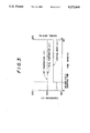
- FIG. 3 is a graphical representation of the operation of the apparatus in FIG. 1;
- FIGS. 4 and 5 are graphical representations showing the timing of the setting order of a compensation input
- FIG. 6 is a block diagram showing a conventional construction of a heat controlling apparatus
- FIG. 7 is a block diagram showing how the conventional apparatus is controlled.
- FIG. 8 is a graphical representation showing a control example based on the conventional apparatus.
- FIG. 1 An apparatus for controlling a heating temperature which is applied to an injection mold machine according to the present invention is schematically shown in FIG. 1.
- the injection mold machine is denoted by the numeral 1 as the object to be heated.
- Denoted by 4 is a heating device.
- Denoted by 10 is a control device to control these devices.
- the injection mold machine 1 and the control device 10 are the same as shown in FIG. 6.
- the same reference numerals will be used to designate the same or similar components as those in the conventional example, so that the description will be simplified.
- the control device 10 is provided with a condition compensating device 20 according to the present invention.
- the condition compensating device 20 controls the heater 4 by issuing a compensation input in response to a reset signal from the control device 10.
- the device 20 consists of a resetting detector 21, a compensation input generator 22, a compensatory data memory 23, and a compensation processor 24.
- the resetting detector 21 receives a command for resetting temperature from a control panel 13.
- the reset command is also received by a temperature setting portion 12 and an operation setting portion 11 for changing the operation state of the injection mold machine 1.
- temperature control elements of the barrel 2 are stored.
- the resetting detector 21 detects the command corresponding to the elements stored therein, turning on the compensation input generator 22.
- the compensation input generator 22 investigates the command input to the resetting detector 21, adjusts the heater 4 as determined by the compensatory data memory 23 and the compensation processor 24.
- the compensatory data memory 23 stores, in the form of a function or data-table, ratios of the necessary quantity of heat in the barrel 2 during each state of the operation of the injection mold machine 1, e.g. the idling operation, the ordinary running operation, and the molding cycle operation.
- the memory 23 also stores ratios of the necessary quantity of heat in response to the molding cycle speed and in response to the set temperature or the fluctuations of the temperature. Accordingly, the appropriate quantity of heat for the barrel 2 can be obtained based on the state of the injection mold machine 1.
- the compensation processor 24 compares the present heat requirement for the injection mold machine, which is issued by the compensatory data memory 23, with the heat required when a reset is issued by the control device 10 to adjust the quantity of heat for the heater 4.
- the adjusted quantity of heat from the condition compensating device 20 is added to the output for the heater 4 by the control device 10 as the compensation input to preliminarily compensate for the probable fluctuation of temperature after resetting.
- the compensatory data memory 23 and the compensation processor 24 are arranged so as to provide a suitable compensation input, which is predetermined from investigations or testing, when conducting a reset of the injection mold machine 1.
- r(t) is a desired set temperature of the temperature setting portion 12
- u(t) is a heating control input from the PID controller 14 to the heater 4.
- Controlled variable y(t) is a real temperature of the barrel 2 based on the heating control and changes in response to the object to be heated and sorts of resin materials fed into the barrel 2.
- the real temperature of the barrel 2 detected by the sensor 15 is negatively fed back to an input of the PID controller 14 in a feed-back control scheme to decrease the deflection e(t) of a set temperature and real temperature. Accordingly, the barrel 2 is set at a predetermined set temperature by the heater 4.
- the temperature fluctuation of the barrel 2 due to the reset by the control device 10 may influence, as a disturbance d(t), the real temperature of the barrel 2.
- the compensation input based on the reset is correspondingly input from the condition compensating device 20 to the heater 4.
- a transfer function of PID controller 14 is expressed as Gc
- a transfer function of the heating device is expressed as Gp
- a transfer function of the disturbance is expressed as Gd
- a transfer function of the compensation input is expressed as Gf
- a transfer function Gf is expressed as -Gd/Gp
- the transfer function of the heating device Gp can be determined as follows.
- the control input u(t), the controlled variable y(t), and the disturbance d(t) are transformed by the Laplace transform and expressed as U(s), Y(s), and D(s).
- control device 10 controls the motion of the injection mold machine 1 and the heating condition of the heater 4 based on the set.
- the operation of the injection mold device 1 is controlled by the operation setting portion 11 and the temperature is kept constant by the temperature setting portion 12.
- the compensation input generator 22 reads the desired quantity of heat at present and after resetting from the compensatory data memory 23.
- the compensation processor 24 calculates the difference in the quantity of heat so that the temperature of the heater 4 can be controlled. Accordingly, the fluctuation of the quantity of heat at the barrel 2 because of the resetting is compensated for, and the barrel 2 is kept at a constant temperature.
- the heating control for slight temperature fluctuations of the barrel 2 under the certain resetting can be carried out at the control device 10.
- the heating control for considerable temperature fluctuations of the barrel 2 because of the resetting can be compensated by the condition compensating device 20.
- the negative effects of the feedback control device 10 resulting in the delay or fluctuation of the heating control after resetting can be kept from occurring.
- the temperature control of the injection mold machine 1 is therefore quickly and accurately controlled.
- the compensation input by the condition compensating device 20 is issued in response to the reset of the temperature and operation state by the control device 10 and enables the injection mold machine 1 to shift its operation state from the preparation step to the molding cycle operation.
- the temporary temperature fluctuation can be minimized to prevent insufficient moldability in the injection mold machine 1 and deterioration of the resin.
- the injection mold machine 1, the heater 4, and the control device 10 each may be of a conventional type, and the condition compensating device 20 which is additionally introduced in the present invention is of a simple construction so that it may be easily utilized by a skilled person in the art.
- the real temperature of the barrel 2 is measured when the molding cycle operation is started under the stable temperature of the heater 4.
- the control input u(t) controls the heater 4 when the maximum heating input is set at 100%.
- the control input u(t) is a total of the outputs from the control device 10 and from the condition compensating device 20.
- the operation input u(t) is increased once in the form of a step in response to the start of the molding cycle operation and thereafter kept constant. The increase results in heating control by the compensation input issued from the condition compensating device 20. Due to the compensation, there is no fluctuation caused by the control device 10. While the operation input u(t) is kept constant, the real temperature y(t) of the barrel 2 is equated with the set temperature (t). It may be recognized that the accurate control is performed without the temperature fluctuation.
- condition compensating device 20 A control system which is not provided with the condition compensating device 20 is hereunder described under the same conditions of the operative example already mentioned.
- the control input u(t) describes the heating control of the heater 4 by the control device 10, and will not deviate at the moment of starting the molding cycle operation.
- the real temperature y(t) of the barrel 2 is considerably decreased, u(t) suddenly increases.
- the real temperature y(t) exceeds the set temperature r(t) in response to the increase of the control input u(t).
- the heating control for the heater 4 is delayed, the real temperature y(t) of the barrel 2 fluctuates considerably, and the heating control requires time to stabilize the real temperature y(t).
- the compensation input corresponding to the various states of resetting may be preliminarily calculated and stored, and its input directly read out when resetting. Otherwise, the fundamental nature of temperature only may be stored and the temporal calculation performed when resetting. These modifications are selective.
- the stored data pattern may be in the form of a function or a data-table.
- the states controllable by the control device 10 are not limited to the operation state of the injection mold machine 1 and the heating condition of the heater 4, but may be any other state.
- the system of the control device 10 may be separated. In this situation, it is preferable to join respective control systems for the heater 4 and the barrel 2 into one condition compensating device.
- the items to be reset are not only the operation state of the injection mold machine 1 and the temperature of the heater 4; any item which may affect the temperature of the barrel 2 may be registered in the condition compensating device 20.
- the object to be heated, the heating device, and the control device are not only the injection mold machine 2, the heater 4, and the control device 10 but any types of heating devices and control devices employed in other kinds of injection mold machines, extruders and the like.
- accurate and stable temperature control may be achieved when temperature fluctuation is caused by the change of the operation state of the object to be heated.
Landscapes
- Engineering & Computer Science (AREA)
- Mechanical Engineering (AREA)
- Physics & Mathematics (AREA)
- Thermal Sciences (AREA)
- General Physics & Mathematics (AREA)
- Automation & Control Theory (AREA)
- Manufacturing & Machinery (AREA)
- Injection Moulding Of Plastics Or The Like (AREA)
- Extrusion Moulding Of Plastics Or The Like (AREA)
- Control Of Temperature (AREA)
Abstract
Description
Claims (8)
Applications Claiming Priority (2)
| Application Number | Priority Date | Filing Date | Title |
|---|---|---|---|
| JP1305480A JPH0661811B2 (en) | 1989-11-24 | 1989-11-24 | Heating temperature control device |
| JP1-305480 | 1989-11-24 |
Publications (1)
| Publication Number | Publication Date |
|---|---|
| US5272644A true US5272644A (en) | 1993-12-21 |
Family
ID=17945666
Family Applications (1)
| Application Number | Title | Priority Date | Filing Date |
|---|---|---|---|
| US07/612,436 Expired - Lifetime US5272644A (en) | 1989-11-24 | 1990-11-14 | Apparatus for controlling a heating temperature |
Country Status (4)
| Country | Link |
|---|---|
| US (1) | US5272644A (en) |
| EP (1) | EP0429959B1 (en) |
| JP (1) | JPH0661811B2 (en) |
| DE (1) | DE69029893T2 (en) |
Cited By (14)
| Publication number | Priority date | Publication date | Assignee | Title |
|---|---|---|---|---|
| US5529477A (en) * | 1992-08-11 | 1996-06-25 | Nissei Plastic Industrial Co., Ltd. | Method and apparatus for temperature correction of an injection molding machine |
| US5551857A (en) * | 1993-11-08 | 1996-09-03 | Fanuc Ltd. | Cylinder temperature controller for an injection molding machine |
| US5589114A (en) * | 1990-11-16 | 1996-12-31 | Evans; Rowland F. | Temperature regulating system, method and apparatus |
| US5777881A (en) * | 1996-01-23 | 1998-07-07 | Tokyo Electron Limited | Method of deciding control parameters of heat treatment instrument and apparatus thereof |
| US5776513A (en) * | 1995-08-10 | 1998-07-07 | Kabushiki Kaisha Meiki Seisakusho | Device for controlling temperature of a nozzle |
| US6461438B1 (en) * | 1999-11-18 | 2002-10-08 | Tokyo Electron Limited | Heat treatment unit, cooling unit and cooling treatment method |
| US20030075833A1 (en) * | 2001-10-18 | 2003-04-24 | Joel Thomson | Apparatus for injection molding multilayered articles |
| US20070001332A1 (en) * | 2003-10-02 | 2007-01-04 | Sumitomo Heavy Industries, Ltd | Injection molding machine and method |
| US20070216054A1 (en) * | 2006-03-20 | 2007-09-20 | Husky Injection Molding Systems Ltd. | Controller for at lest one heater utilized in an injection molding system and an associated method of use |
| US20080039970A1 (en) * | 2006-08-14 | 2008-02-14 | Husky Injection Molding Systems Ltd. | Thermal management of extruder of molding system, amongst other things |
| US20090115086A1 (en) * | 2007-11-06 | 2009-05-07 | Husky Injection Molding Systems Ltd | Method of Molding System, Including Raising Temperature of Feedstock Responsive to a Calculated Amount of Thermal Energy |
| US20090166909A1 (en) * | 2007-12-28 | 2009-07-02 | Chung Yuan Christian University | Temperature control system for molding facility |
| US20100249983A1 (en) * | 2003-10-10 | 2010-09-30 | Boston Scientific Scimed, Inc. | Extrusion of articles |
| US20110269084A1 (en) * | 2010-04-28 | 2011-11-03 | Toshiba Kikai Kabushiki Kaisha | Automatic temperature rise control method for molding machine |
Families Citing this family (9)
| Publication number | Priority date | Publication date | Assignee | Title |
|---|---|---|---|---|
| US5149193A (en) * | 1991-01-15 | 1992-09-22 | Crompton & Knowles Corporation | Extruder temperature controller and method for controlling extruder temperature |
| JPH06180613A (en) * | 1992-12-14 | 1994-06-28 | Toshiba Mach Co Ltd | Heating temperature controller |
| DE19851826A1 (en) * | 1998-11-10 | 2000-05-11 | Siemens Ag | Process for identifying a delayed process with compensation and device for regulating such a process |
| JP3277490B2 (en) * | 2000-03-27 | 2002-04-22 | 住友重機械工業株式会社 | Control method of injection molding machine |
| KR101113079B1 (en) * | 2011-09-02 | 2012-02-29 | 신영구 | Method of sewage high-speed treatment |
| KR101113075B1 (en) * | 2011-09-02 | 2012-02-29 | 신영구 | Sewage high-speed treatment unit |
| JP5946732B2 (en) * | 2012-09-24 | 2016-07-06 | ファナック株式会社 | Temperature control device for injection molding machine having temperature correction function and temperature control method for injection molding machine |
| JP6001411B2 (en) | 2012-10-29 | 2016-10-05 | 日本特殊陶業株式会社 | Heater control device and sensor control system |
| JP6874696B2 (en) * | 2018-01-09 | 2021-05-19 | オムロン株式会社 | Heating device |
Citations (9)
| Publication number | Priority date | Publication date | Assignee | Title |
|---|---|---|---|---|
| US4102958A (en) * | 1974-05-02 | 1978-07-25 | Owens-Illinois, Inc. | Method of controlling an extruder |
| WO1980002871A1 (en) * | 1979-06-15 | 1980-12-24 | Crompton & Knowles Corp | Extruder temperature controller |
| JPS58127201A (en) * | 1981-10-05 | 1983-07-29 | Yamatake Honeywell Co Ltd | Indicating controller |
| US4430698A (en) * | 1981-08-20 | 1984-02-07 | Harrel, Incorporated | Three-mode process control |
| USRE31903E (en) * | 1979-06-15 | 1985-06-04 | Crompton & Knowles Corporation | Extruder temperature controller |
| US4695237A (en) * | 1983-12-28 | 1987-09-22 | Fanuc Ltd. | Injection molding apparatus |
| US4843576A (en) * | 1987-04-15 | 1989-06-27 | Westinghouse Electric Corp. | Temperature control arrangement for an extruding process |
| US5062053A (en) * | 1988-11-09 | 1991-10-29 | Toshiba Machine Co., Ltd. | Fully automatic operation system for injection molding machines |
| US5088911A (en) * | 1989-02-02 | 1992-02-18 | Toshiba Kikai Kabushiki Kaisha | Injection molding apparatus for controlling molding optimum condition in response to temperature |
Family Cites Families (3)
| Publication number | Priority date | Publication date | Assignee | Title |
|---|---|---|---|---|
| JPS4419961Y1 (en) * | 1964-11-09 | 1969-08-27 | ||
| JPS6010893A (en) * | 1983-06-29 | 1985-01-21 | Pioneer Electronic Corp | Key signal detecting circuit in chromakey system |
| JP2512519B2 (en) * | 1988-03-10 | 1996-07-03 | 東芝機械株式会社 | Extruder cylinder temperature control method |
-
1989
- 1989-11-24 JP JP1305480A patent/JPH0661811B2/en not_active Expired - Lifetime
-
1990
- 1990-11-14 US US07/612,436 patent/US5272644A/en not_active Expired - Lifetime
- 1990-11-14 DE DE69029893T patent/DE69029893T2/en not_active Expired - Fee Related
- 1990-11-14 EP EP90121813A patent/EP0429959B1/en not_active Expired - Lifetime
Patent Citations (9)
| Publication number | Priority date | Publication date | Assignee | Title |
|---|---|---|---|---|
| US4102958A (en) * | 1974-05-02 | 1978-07-25 | Owens-Illinois, Inc. | Method of controlling an extruder |
| WO1980002871A1 (en) * | 1979-06-15 | 1980-12-24 | Crompton & Knowles Corp | Extruder temperature controller |
| USRE31903E (en) * | 1979-06-15 | 1985-06-04 | Crompton & Knowles Corporation | Extruder temperature controller |
| US4430698A (en) * | 1981-08-20 | 1984-02-07 | Harrel, Incorporated | Three-mode process control |
| JPS58127201A (en) * | 1981-10-05 | 1983-07-29 | Yamatake Honeywell Co Ltd | Indicating controller |
| US4695237A (en) * | 1983-12-28 | 1987-09-22 | Fanuc Ltd. | Injection molding apparatus |
| US4843576A (en) * | 1987-04-15 | 1989-06-27 | Westinghouse Electric Corp. | Temperature control arrangement for an extruding process |
| US5062053A (en) * | 1988-11-09 | 1991-10-29 | Toshiba Machine Co., Ltd. | Fully automatic operation system for injection molding machines |
| US5088911A (en) * | 1989-02-02 | 1992-02-18 | Toshiba Kikai Kabushiki Kaisha | Injection molding apparatus for controlling molding optimum condition in response to temperature |
Non-Patent Citations (5)
| Title |
|---|
| Barthel et al., "Self-Optimizing Temperature Controllers Reduce Commissioning Time and Costs", Siemens Energy & Automation, vol. 9, No. 4, Jul. 1987 pp. 16-18. |
| Barthel et al., Self Optimizing Temperature Controllers Reduce Commissioning Time and Costs , Siemens Energy & Automation, vol. 9, No. 4, Jul. 1987 pp. 16 18. * |
| Chan, "Simple Overshoot-Suppressed Digital Proportional-Integral-Derivative Temperature Controller", Review of Scientific Instruments, vol. 59 No. 6, Jun. 1988, pp. 1001-1003. |
| Chan, Simple Overshoot Suppressed Digital Proportional Integral Derivative Temperature Controller , Review of Scientific Instruments, vol. 59 No. 6, Jun. 1988, pp. 1001 1003. * |
| Patent Abstracts of Japan, vol. 12, No. 157, May 1988. * |
Cited By (23)
| Publication number | Priority date | Publication date | Assignee | Title |
|---|---|---|---|---|
| US5589114A (en) * | 1990-11-16 | 1996-12-31 | Evans; Rowland F. | Temperature regulating system, method and apparatus |
| US5529477A (en) * | 1992-08-11 | 1996-06-25 | Nissei Plastic Industrial Co., Ltd. | Method and apparatus for temperature correction of an injection molding machine |
| US5551857A (en) * | 1993-11-08 | 1996-09-03 | Fanuc Ltd. | Cylinder temperature controller for an injection molding machine |
| US5776513A (en) * | 1995-08-10 | 1998-07-07 | Kabushiki Kaisha Meiki Seisakusho | Device for controlling temperature of a nozzle |
| US5777881A (en) * | 1996-01-23 | 1998-07-07 | Tokyo Electron Limited | Method of deciding control parameters of heat treatment instrument and apparatus thereof |
| US6461438B1 (en) * | 1999-11-18 | 2002-10-08 | Tokyo Electron Limited | Heat treatment unit, cooling unit and cooling treatment method |
| US6686571B2 (en) | 1999-11-18 | 2004-02-03 | Tokyo Electron Limited | Heat treatment unit, cooling unit and cooling treatment method |
| US20030075833A1 (en) * | 2001-10-18 | 2003-04-24 | Joel Thomson | Apparatus for injection molding multilayered articles |
| US7004739B2 (en) * | 2001-10-18 | 2006-02-28 | Community Enterprises, Llc | Apparatus for injection molding multilayered articles |
| US20070001332A1 (en) * | 2003-10-02 | 2007-01-04 | Sumitomo Heavy Industries, Ltd | Injection molding machine and method |
| US20100249983A1 (en) * | 2003-10-10 | 2010-09-30 | Boston Scientific Scimed, Inc. | Extrusion of articles |
| US8121721B2 (en) * | 2003-10-10 | 2012-02-21 | Boston Scientific Scimed, Inc. | Extrusion of articles |
| US20070216054A1 (en) * | 2006-03-20 | 2007-09-20 | Husky Injection Molding Systems Ltd. | Controller for at lest one heater utilized in an injection molding system and an associated method of use |
| US7418992B2 (en) * | 2006-03-20 | 2008-09-02 | Husky Injection Molding Systems Ltd. | Controller for at least one heater utilized in an injection molding system and an associated method of use |
| US7618566B2 (en) | 2006-03-20 | 2009-11-17 | Husky Injection Molding Systems Ltd. | Controller for at least one heater utilized in a hot runner injection molding system and an associated method of use |
| US20070215598A1 (en) * | 2006-03-20 | 2007-09-20 | Husky Injection Molding Systems Ltd. | Controller for a heater and an associated method of use |
| US7653460B2 (en) * | 2006-08-14 | 2010-01-26 | Husky Injection Molding Systems Ltd. | Thermal management of extruder of molding system, amongst other things |
| US20080039970A1 (en) * | 2006-08-14 | 2008-02-14 | Husky Injection Molding Systems Ltd. | Thermal management of extruder of molding system, amongst other things |
| US20090115086A1 (en) * | 2007-11-06 | 2009-05-07 | Husky Injection Molding Systems Ltd | Method of Molding System, Including Raising Temperature of Feedstock Responsive to a Calculated Amount of Thermal Energy |
| US7695654B2 (en) | 2007-11-06 | 2010-04-13 | Husky Injection Molding Systems Ltd. | Method of molding system, including raising temperature of feedstock responsive to a calculated amount of thermal energy |
| US20090166909A1 (en) * | 2007-12-28 | 2009-07-02 | Chung Yuan Christian University | Temperature control system for molding facility |
| US20110269084A1 (en) * | 2010-04-28 | 2011-11-03 | Toshiba Kikai Kabushiki Kaisha | Automatic temperature rise control method for molding machine |
| US9592630B2 (en) * | 2010-04-28 | 2017-03-14 | Toshiba Kikai Kabushiki Kaisha | Automatic temperature rise control method for molding machine |
Also Published As
| Publication number | Publication date |
|---|---|
| EP0429959A3 (en) | 1992-07-22 |
| JPH03164224A (en) | 1991-07-16 |
| DE69029893T2 (en) | 1997-05-22 |
| EP0429959A2 (en) | 1991-06-05 |
| DE69029893D1 (en) | 1997-03-20 |
| JPH0661811B2 (en) | 1994-08-17 |
| EP0429959B1 (en) | 1997-02-05 |
Similar Documents
| Publication | Publication Date | Title |
|---|---|---|
| US5272644A (en) | Apparatus for controlling a heating temperature | |
| US4721589A (en) | Extruder viscosity control system and method | |
| US3612165A (en) | Temperature controllers | |
| DE69220624T2 (en) | METHOD AND DEVICE FOR CONTROLLING THE EXTRUDER TEMPERATURE | |
| US3698844A (en) | Automatic temperature control system for extruders for molten material | |
| US4932854A (en) | Apparatus for control of injection molding machine | |
| US4326255A (en) | Apparatus for controlling plasticizing process of in-line screw-type injection molding machine | |
| US9333674B2 (en) | Kneading/extruding equipment with feedforward control of latter stage pump | |
| US5486105A (en) | Apparatus for controlling a heating temperature | |
| DE60103367T2 (en) | METHOD FOR OPERATING A TEMPERATURE CONTROLLER WITH A STABLE TEMPERATURE RESET | |
| US4290986A (en) | Method for controlling a plastic extruder | |
| DE60116057T2 (en) | STABLE RESERVOIR BEHAVIOR EXTRUDER CYLINDER TEMPERATURE CONTROLLER | |
| US5551857A (en) | Cylinder temperature controller for an injection molding machine | |
| US4804505A (en) | Method of operating a screw extruder and screw extruders for carrying out said methods | |
| US5380181A (en) | Control device for an electric injection molding machine | |
| US5355938A (en) | Temperature control device | |
| JPH03502186A (en) | Processing equipment for thermoplastic synthetic materials | |
| US4256678A (en) | Method of and apparatus for controlling resin plasticizing process of in-line screw-type injection molding machines | |
| JPH04125123A (en) | Operation control method for resin extrusion molding device and its device | |
| JPH0124055B2 (en) | ||
| JP2001265408A (en) | Device and method for controlling temperature of heat system plant | |
| JP2002361705A (en) | Method and apparatus for controlling temperature of injection molding machine | |
| DE3833776A1 (en) | Apparatus for the extrusion of a thermoplastic melt | |
| EP0388863B1 (en) | Temperature control device | |
| JPH05228973A (en) | Method and device for controlling temperature of injection equipment |
Legal Events
| Date | Code | Title | Description |
|---|---|---|---|
| AS | Assignment |
Owner name: TOSHIBA KIKAI KABUSHIKI KAISHA, JAPAN Free format text: ASSIGNMENT OF ASSIGNORS INTEREST.;ASSIGNORS:KATSUMATA, HIROFUMI;FUJIE, HIDEO;TOMIKAWA, KAZUTO;AND OTHERS;REEL/FRAME:005508/0299 Effective date: 19901026 |
|
| STCF | Information on status: patent grant |
Free format text: PATENTED CASE |
|
| FEPP | Fee payment procedure |
Free format text: PAYOR NUMBER ASSIGNED (ORIGINAL EVENT CODE: ASPN); ENTITY STATUS OF PATENT OWNER: LARGE ENTITY |
|
| FPAY | Fee payment |
Year of fee payment: 4 |
|
| FPAY | Fee payment |
Year of fee payment: 8 |
|
| AS | Assignment |
Owner name: FOOTHILL CAPITAL CORPORATION, CALIFORNIA Free format text: SECURITY AGREEMENT;ASSIGNOR:SILICON GRAPHICS, INC.;REEL/FRAME:012428/0236 Effective date: 20011109 |
|
| AS | Assignment |
Owner name: U.S. BANK NATIONAL ASSOCIATION, AS TRUSTEE, CALIFO Free format text: SECURITY INTEREST;ASSIGNOR:SILICON GRAPHICS, INC.;REEL/FRAME:014805/0855 Effective date: 20031223 |
|
| FPAY | Fee payment |
Year of fee payment: 12 |