US5268822A - Lead frame for anodes of electrolytic capacitors and process of manufacture of electrolytic capacitors using such a lead frame - Google Patents
Lead frame for anodes of electrolytic capacitors and process of manufacture of electrolytic capacitors using such a lead frame Download PDFInfo
- Publication number
- US5268822A US5268822A US07/847,064 US84706492A US5268822A US 5268822 A US5268822 A US 5268822A US 84706492 A US84706492 A US 84706492A US 5268822 A US5268822 A US 5268822A
- Authority
- US
- United States
- Prior art keywords
- tab
- lead frame
- window
- anode block
- block
- Prior art date
- Legal status (The legal status is an assumption and is not a legal conclusion. Google has not performed a legal analysis and makes no representation as to the accuracy of the status listed.)
- Expired - Fee Related
Links
- 239000003990 capacitor Substances 0.000 title claims abstract description 26
- 238000004519 manufacturing process Methods 0.000 title claims abstract description 10
- 238000000034 method Methods 0.000 title claims description 5
- 229910052782 aluminium Inorganic materials 0.000 claims description 13
- XAGFODPZIPBFFR-UHFFFAOYSA-N aluminium Chemical compound [Al] XAGFODPZIPBFFR-UHFFFAOYSA-N 0.000 claims description 13
- 238000005476 soldering Methods 0.000 claims description 11
- GUVRBAGPIYLISA-UHFFFAOYSA-N tantalum atom Chemical compound [Ta] GUVRBAGPIYLISA-UHFFFAOYSA-N 0.000 claims description 10
- 239000004411 aluminium Substances 0.000 claims description 8
- 229910052715 tantalum Inorganic materials 0.000 claims description 8
- 239000003792 electrolyte Substances 0.000 claims description 7
- 238000005470 impregnation Methods 0.000 claims description 7
- 230000003647 oxidation Effects 0.000 claims description 7
- 238000007254 oxidation reaction Methods 0.000 claims description 7
- 238000005087 graphitization Methods 0.000 claims description 6
- OKTJSMMVPCPJKN-UHFFFAOYSA-N Carbon Chemical compound [C] OKTJSMMVPCPJKN-UHFFFAOYSA-N 0.000 claims description 4
- 239000010439 graphite Substances 0.000 claims description 4
- 229910002804 graphite Inorganic materials 0.000 claims description 4
- 238000004382 potting Methods 0.000 claims description 4
- 239000007784 solid electrolyte Substances 0.000 claims description 4
- 238000010276 construction Methods 0.000 claims description 3
- 238000005530 etching Methods 0.000 claims description 3
- 238000005096 rolling process Methods 0.000 claims description 3
- 238000005245 sintering Methods 0.000 claims description 3
- 238000002048 anodisation reaction Methods 0.000 claims description 2
- 230000004888 barrier function Effects 0.000 claims description 2
- 230000008021 deposition Effects 0.000 claims description 2
- 238000000465 moulding Methods 0.000 claims description 2
- 239000000843 powder Substances 0.000 claims 2
- 150000001875 compounds Chemical class 0.000 claims 1
- 230000000149 penetrating effect Effects 0.000 claims 1
- 238000009736 wetting Methods 0.000 description 4
- 239000000463 material Substances 0.000 description 3
- 229910000679 solder Inorganic materials 0.000 description 3
- 230000015572 biosynthetic process Effects 0.000 description 2
- 238000002791 soaking Methods 0.000 description 2
- 239000007787 solid Substances 0.000 description 2
- PNEYBMLMFCGWSK-UHFFFAOYSA-N aluminium oxide Inorganic materials [O-2].[O-2].[O-2].[Al+3].[Al+3] PNEYBMLMFCGWSK-UHFFFAOYSA-N 0.000 description 1
- 230000007423 decrease Effects 0.000 description 1
- 230000000694 effects Effects 0.000 description 1
- 239000007788 liquid Substances 0.000 description 1
- MIVBAHRSNUNMPP-UHFFFAOYSA-N manganese(2+);dinitrate Chemical compound [Mn+2].[O-][N+]([O-])=O.[O-][N+]([O-])=O MIVBAHRSNUNMPP-UHFFFAOYSA-N 0.000 description 1
- 229910052751 metal Inorganic materials 0.000 description 1
- 239000002184 metal Substances 0.000 description 1
- 238000000197 pyrolysis Methods 0.000 description 1
- 239000011347 resin Substances 0.000 description 1
- 229920005989 resin Polymers 0.000 description 1
- 230000000007 visual effect Effects 0.000 description 1
- 239000002699 waste material Substances 0.000 description 1
Images

Classifications
-
- H—ELECTRICITY
- H01—ELECTRIC ELEMENTS
- H01G—CAPACITORS; CAPACITORS, RECTIFIERS, DETECTORS, SWITCHING DEVICES, LIGHT-SENSITIVE OR TEMPERATURE-SENSITIVE DEVICES OF THE ELECTROLYTIC TYPE
- H01G9/00—Electrolytic capacitors, rectifiers, detectors, switching devices, light-sensitive or temperature-sensitive devices; Processes of their manufacture
- H01G9/004—Details
- H01G9/008—Terminals
Definitions
- the present invention concerns the manufacture of electrolytic capacitors, more particularly the lead frames for electrolytic capacitor anodes.
- electrolytic capacitors are generally made using an aluminium or tantalum anode and an electrolyte which may be solid or liquid.
- a process of manufacture of capacitors with aluminium and with a solid electrolyte comprises several stages, a similar process being usable for capacitors with tantalum and a solid electrolyte. These stages are principally:
- construction of the anode block either by compacting an aluminium wire, or by etching, folding or rolling of a sheet of aluminium, or by sintering;
- connection of the anode block to the tab of the lead frame which is performed by soldering, is subject to dimensional constraints to be respected to take into account the different phases of manufacture.
- the anodized blocks are soaked in different solutions which have good wettability, and it can be observed that the conducting electrolyte and graphite rise by capillary action around the solder. There is therefore a risk of short-circuiting between the non-oxidized anode and the cathode constituted by the electrolyte. This rise by capillarity is not controllable and varies depending on the materials and their surface states.
- the present invention proposes a mechanical means to eliminate this capillary effect, while enabling the necessary dimensions to be reduced. By reducing the height of oxidation with respect to that of impregnation and graphitization, it decreases the loss of active volume.
- the invention consists of a lead frame for electrolytic capacitor anodes, characterized by the fact that it comprises, for each anode to be connected, a tab with, close to its free end, a means preventing the rise by capillary action, without hindering the soldering of the anode block.
- the invention also concerns a process for manufacture of an electrolytic capacitor using such a lead frame.
- FIG. 1 represents a lead frame for electrolytic capacitors according to the prior art
- FIG. 2 represents a lead frame for electrolytic capacitors according to the invention.
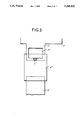
- FIG. 3 represents a variant embodiment of the present invention.
- FIG. 1 shows part of a lead frame 1.
- This frame can be made of aluminium or tantalum or any other metal compatible with the anode of the capacitor. It is provided with tabs 2 of the same material. On one of them has been soldered the connecting wire 3 from an anode block 4.
- This soldering 5 is performed before soaking the anode in the various baths for oxidation of the anode block, then the deposition or impregnation of the electrolyte and finally the graphitization. After soaking in these baths, a rise by capillarity 6 is seen around the solder 5, to a height which is not controllable.
- the height Y represents the tolerance for the bath level in the impregnation and graphitization phases
- the height X is the height lost for the active volume of the capacitor.
- the oxidation must go up to the limit h on FIG. 1, which for given external dimensions reduces the active volume of the capacitor.
- FIG. 2 A mode of embodiment of the present invention is represented in FIG. 2.
- the lead frame 1' has been improved over that seen previously.
- a rectangular window 7' is cut in the tab 2' leaving sufficient space between itself and the edge of the tab 2' to enable soldering 5' of the anode block 4'.
- the window 7' stops the rise by capillarity 6' and imposes the height Z'.
- This height Z' is fixed. For this reason, the oxidized level can safely be brought nearer. As a consequence, the distance X' between the soldering and the oxidation level is less than the distance X and has been reduced by the difference between Z and Z'.
- the window 7' may be of various shapes. It may be rectangular, round, or of any shape as long as its dimensions are sufficient to form a barrier to the capillary rise, while still leaving a sufficiently solid connection tab. It is preferably at least 0.3 mm thick and its length is preferably 0.5 to 0.7 times the width of the tab.
- a window was made 0.3 mm thick and 1.6 mm wide on a connection tab 2.4 mm wide. This window is 0.3 mm from the free end of the tab.
- wetting is observed over a length of 0.9 to 1.2 mm. This wetting is not controllable and varies depending on the materials and their surface states; but it should be noted that wetting is greater with graphite than with manganese nitrate. The present invention therefore limits the extent of this wetting.
- This invention also has other advantages.
- the window can also be used as a visual level mark during the various steps in manufacture.
- the window 7' enables soldering of the anode block 4' at the very edge of the tab 2' of the lead frame 1', avoiding the waste of a length of inactive anode.
- the resin used penetrates the window 7' and thus provides better anchorage in the connection tab.
- the window 7' may be pierced before or after the soldering 5' of the anode blocks 4' on the tabs 2' of the lead frame 1', and in either case, the window 7' enables excess wire 3' to be cut off above the solder 5'.
- the window 7" can be relatively thick.
- the window serves to identify the anode 2".
- FIG. 3 then represents part of a lead frame 1" whose tabs 2" are pierced by a window 7" which is thicker than that in FIG. 2. Consequently, once the capacitor 4" is finished, the anode 2" can be distinguished from the cathode 8", thanks to the window 7" which is not completely potted or molded.
Landscapes
- Engineering & Computer Science (AREA)
- Power Engineering (AREA)
- Microelectronics & Electronic Packaging (AREA)
- Fixed Capacitors And Capacitor Manufacturing Machines (AREA)
Abstract
The object of the invention is a lead frame for electrolytic capacitor anodes characterized by the fact that it comprises, for each anode to be connected, a tab with near its free end a window, the said window being sufficiently large to stop the rise by capillary action which can occur during manufacture of electrolytic capacitors.
Description
The present invention concerns the manufacture of electrolytic capacitors, more particularly the lead frames for electrolytic capacitor anodes.
At present, electrolytic capacitors are generally made using an aluminium or tantalum anode and an electrolyte which may be solid or liquid.
A process of manufacture of capacitors with aluminium and with a solid electrolyte comprises several stages, a similar process being usable for capacitors with tantalum and a solid electrolyte. These stages are principally:
construction of the anode block either by compacting an aluminium wire, or by etching, folding or rolling of a sheet of aluminium, or by sintering;
soldering of the anode block onto a tab of a lead frame;
anodization of the aluminium block to form a thin layer of alumina (oxidation);
formation of the solid electrolyte (impregnation and pyrolysis);
formation of the cathode (graphitization and/or silvering); and
molding or potting.
The manufacturing process of these capacitors is rather complicated and the problems presently encountered during the manufacture of electrolytic capacitors are of several types.
The connection of the anode block to the tab of the lead frame, which is performed by soldering, is subject to dimensional constraints to be respected to take into account the different phases of manufacture.
To deposit the electrolyte and then the graphite, the anodized blocks are soaked in different solutions which have good wettability, and it can be observed that the conducting electrolyte and graphite rise by capillary action around the solder. There is therefore a risk of short-circuiting between the non-oxidized anode and the cathode constituted by the electrolyte. This rise by capillarity is not controllable and varies depending on the materials and their surface states.
To prevent such short-circuiting, dimensions are imposed: a minimum height for the oxidation of the tab of the lead frame and a lower minimum height for electrolytic impregnation and graphitization, taking into account the capillary rise. There is therefore an oxidized part of the anode which is not impregnated and which is inactive from a capacitive point of view.
The present invention proposes a mechanical means to eliminate this capillary effect, while enabling the necessary dimensions to be reduced. By reducing the height of oxidation with respect to that of impregnation and graphitization, it decreases the loss of active volume.
The invention consists of a lead frame for electrolytic capacitor anodes, characterized by the fact that it comprises, for each anode to be connected, a tab with, close to its free end, a means preventing the rise by capillary action, without hindering the soldering of the anode block.
The invention also concerns a process for manufacture of an electrolytic capacitor using such a lead frame.
The invention will be better understood and other advantages will appear on reading the description of a preferred mode of embodiment, with reference to the appended drawings of which:
FIG. 1 represents a lead frame for electrolytic capacitors according to the prior art;
FIG. 2 represents a lead frame for electrolytic capacitors according to the invention; and
FIG. 3 represents a variant embodiment of the present invention.
FIG. 1 shows part of a lead frame 1. This frame can be made of aluminium or tantalum or any other metal compatible with the anode of the capacitor. It is provided with tabs 2 of the same material. On one of them has been soldered the connecting wire 3 from an anode block 4. This soldering 5 is performed before soaking the anode in the various baths for oxidation of the anode block, then the deposition or impregnation of the electrolyte and finally the graphitization. After soaking in these baths, a rise by capillarity 6 is seen around the solder 5, to a height which is not controllable. If the height Y represents the tolerance for the bath level in the impregnation and graphitization phases, then the height X is the height lost for the active volume of the capacitor. For safety reasons, the oxidation must go up to the limit h on FIG. 1, which for given external dimensions reduces the active volume of the capacitor.
A mode of embodiment of the present invention is represented in FIG. 2. In this case, the lead frame 1' has been improved over that seen previously. A rectangular window 7' is cut in the tab 2' leaving sufficient space between itself and the edge of the tab 2' to enable soldering 5' of the anode block 4'. The window 7' stops the rise by capillarity 6' and imposes the height Z'. This height Z' is fixed. For this reason, the oxidized level can safely be brought nearer. As a consequence, the distance X' between the soldering and the oxidation level is less than the distance X and has been reduced by the difference between Z and Z'.
The window 7' may be of various shapes. It may be rectangular, round, or of any shape as long as its dimensions are sufficient to form a barrier to the capillary rise, while still leaving a sufficiently solid connection tab. It is preferably at least 0.3 mm thick and its length is preferably 0.5 to 0.7 times the width of the tab.
As an example, a window was made 0.3 mm thick and 1.6 mm wide on a connection tab 2.4 mm wide. This window is 0.3 mm from the free end of the tab. For a connection made by a soldering of dimension 0.3 to 0.4 mm, of a 0.3 mm wire on such a connection tab, wetting is observed over a length of 0.9 to 1.2 mm. This wetting is not controllable and varies depending on the materials and their surface states; but it should be noted that wetting is greater with graphite than with manganese nitrate. The present invention therefore limits the extent of this wetting.
This invention also has other advantages.
The window can also be used as a visual level mark during the various steps in manufacture.
The window 7' enables soldering of the anode block 4' at the very edge of the tab 2' of the lead frame 1', avoiding the waste of a length of inactive anode.
During the final potting phase, the resin used penetrates the window 7' and thus provides better anchorage in the connection tab.
The window 7' may be pierced before or after the soldering 5' of the anode blocks 4' on the tabs 2' of the lead frame 1', and in either case, the window 7' enables excess wire 3' to be cut off above the solder 5'.
According to a variant of the present invention represented in FIG. 3, the window 7" can be relatively thick. In this case, the window serves to identify the anode 2". FIG. 3 then represents part of a lead frame 1" whose tabs 2" are pierced by a window 7" which is thicker than that in FIG. 2. Consequently, once the capacitor 4" is finished, the anode 2" can be distinguished from the cathode 8", thanks to the window 7" which is not completely potted or molded.
Claims (12)
1. Lead frame for anodes for electrolytic capacitors, said anodes being manufactured by the construction of an anode block either by compacting an aluminum or tantalum wire, or by etching or folding or rolling of a sheet of aluminum or tantalum, or by sintering of a powder of aluminum or tantalum, said lead frame comprising a tab soldered to said anode block, wherein said tab comprises a window which eliminates a conducting electrolyte and graphite rise by capillarity action when said anode block is soaked in baths of deposition or impregnation of the electrolyte and of graphitization.
2. Lead frame according to claim 1, wherein the window is rectangular, square or round.
3. Lead frame according to claim 2, wherein the window has a length of between 0.5 and 0.7 times the width of a tab.
4. Lead frame according to any one of claims 1, 2 or 3, wherein the window is at least 0.3 mm thick.
5. Lead frame according to claim 4, wherein said tab is made of aluminum or tantalum.
6. Process of manufacture of an electrolytic capacitor using a lead frame according to any one of claims 1, 2 or 3, characterized by the following steps:
i--construction of the anode block either by compacting an aluminium or tantalum wire, or by etching or folding or rolling of a sheet of aluminum or tantalum, or by sintering of a powder of aluminium or tantalum;
ii--soldering of the anode block to a tab of the lead frame at the edge of the tab;
iii--anodization of the anode block to form a thin dielectric layer, the window serving as a dimension guide, then in known manner;
iv--formation of the solid electrolyte;
v--fitting of the cathode followed by potting or molding.
7. Lead frame according to claim 4 wherein there is a space between said window and the edge of said tab to enable soldering of said anode block.
8. An electrolytic capacitor comprising an anode block (4'); a lead frame (1') having a tab (2') attached by a joint (3') to said anode block before said block is oxidized and impregnated; said tab comprising a window (7') adjacent one end of said joint; and said window having dimensions sufficient to form a barrier to capillary rise during said oxidation and impregnation, and to also permit sufficient mechanical support of said one end of said tab to said joint and said block.
9. A capacitor according to claim 8 wherein said window (7') is in the range of 0.5 to 0.7 times a width of said tab.
10. A capacitor according to claim 9 where said tab is about 2.4 mm wide, and said window is about 1.6 mm wide and about 0.3 mm thick, and about 0.3 mm from a free end of said tab, and said joint (5') is in the range of about 0.3 to 0.4 mm wide.
11. A capacitor according to claim 8 wherein said joint (3') is a soldered joint of a wire.
12. A capacitor according to claim 8 further comprising a potting compound encasing said block and said lead frame tab and penetrating into said window thereby providing better anchorage of the connecting tab to said block.
Applications Claiming Priority (2)
| Application Number | Priority Date | Filing Date | Title |
|---|---|---|---|
| FR9010248 | 1990-08-10 | ||
| FR9010248A FR2665796A1 (en) | 1990-08-10 | 1990-08-10 | CONNECTION STRIP FOR ELECTROLYTIC CAPACITOR ANODES AND METHOD FOR MANUFACTURING ELECTROLYTIC CAPACITORS USING SUCH A STRIP. |
Publications (1)
| Publication Number | Publication Date |
|---|---|
| US5268822A true US5268822A (en) | 1993-12-07 |
Family
ID=9399606
Family Applications (1)
| Application Number | Title | Priority Date | Filing Date |
|---|---|---|---|
| US07/847,064 Expired - Fee Related US5268822A (en) | 1990-08-10 | 1991-08-02 | Lead frame for anodes of electrolytic capacitors and process of manufacture of electrolytic capacitors using such a lead frame |
Country Status (6)
| Country | Link |
|---|---|
| US (1) | US5268822A (en) |
| EP (1) | EP0495067B1 (en) |
| DE (1) | DE69113433D1 (en) |
| FR (1) | FR2665796A1 (en) |
| MY (1) | MY107959A (en) |
| WO (1) | WO1992002943A1 (en) |
Cited By (3)
| Publication number | Priority date | Publication date | Assignee | Title |
|---|---|---|---|---|
| US5812190A (en) * | 1995-04-11 | 1998-09-22 | Thomson-Csf | Detection method using distributed read and integration cycles for scanning camera and corresponding detection array |
| US5998777A (en) * | 1996-07-16 | 1999-12-07 | Thomson-Csf | Circuit for the reading of linear arrays of photodetectors |
| US20050002148A1 (en) * | 2003-07-04 | 2005-01-06 | Nec Tokin Corporation | Chip-type solid electrolytic capacitor superior in productivity and reliability thereof |
Citations (4)
| Publication number | Priority date | Publication date | Assignee | Title |
|---|---|---|---|---|
| US4483062A (en) * | 1980-10-31 | 1984-11-20 | Matsushita Electric Industrial Co., Ltd. | Method for manufacturing solid electrolyte condensers |
| US4539623A (en) * | 1980-04-02 | 1985-09-03 | Matsushita Electric Industrial Company, Limited | Solid electrolytic chip capacitor with improved terminals |
| FR2625832A1 (en) * | 1988-01-08 | 1989-07-13 | Europ Composants Electron | Process for manufacture of electrolytic capacitors with aluminium and wire anode capacitor obtained by this process |
| US5007149A (en) * | 1989-09-19 | 1991-04-16 | Siemens Aktiengesellschaft | Method for manufacturing a solid electrolyte capacitor in a chip structure |
-
1990
- 1990-08-10 FR FR9010248A patent/FR2665796A1/en active Pending
-
1991
- 1991-08-02 US US07/847,064 patent/US5268822A/en not_active Expired - Fee Related
- 1991-08-02 EP EP91914732A patent/EP0495067B1/en not_active Expired - Lifetime
- 1991-08-02 DE DE69113433T patent/DE69113433D1/en not_active Expired - Lifetime
- 1991-08-02 WO PCT/FR1991/000644 patent/WO1992002943A1/en not_active Ceased
- 1991-08-05 MY MYPI91001415A patent/MY107959A/en unknown
Patent Citations (4)
| Publication number | Priority date | Publication date | Assignee | Title |
|---|---|---|---|---|
| US4539623A (en) * | 1980-04-02 | 1985-09-03 | Matsushita Electric Industrial Company, Limited | Solid electrolytic chip capacitor with improved terminals |
| US4483062A (en) * | 1980-10-31 | 1984-11-20 | Matsushita Electric Industrial Co., Ltd. | Method for manufacturing solid electrolyte condensers |
| FR2625832A1 (en) * | 1988-01-08 | 1989-07-13 | Europ Composants Electron | Process for manufacture of electrolytic capacitors with aluminium and wire anode capacitor obtained by this process |
| US5007149A (en) * | 1989-09-19 | 1991-04-16 | Siemens Aktiengesellschaft | Method for manufacturing a solid electrolyte capacitor in a chip structure |
Cited By (4)
| Publication number | Priority date | Publication date | Assignee | Title |
|---|---|---|---|---|
| US5812190A (en) * | 1995-04-11 | 1998-09-22 | Thomson-Csf | Detection method using distributed read and integration cycles for scanning camera and corresponding detection array |
| US5998777A (en) * | 1996-07-16 | 1999-12-07 | Thomson-Csf | Circuit for the reading of linear arrays of photodetectors |
| US20050002148A1 (en) * | 2003-07-04 | 2005-01-06 | Nec Tokin Corporation | Chip-type solid electrolytic capacitor superior in productivity and reliability thereof |
| US6903921B2 (en) * | 2003-07-04 | 2005-06-07 | Nec Tokin Corporation | Chip-type solid electrolytic capacitor superior in productivity and reliability thereof |
Also Published As
| Publication number | Publication date |
|---|---|
| DE69113433D1 (en) | 1995-11-02 |
| EP0495067B1 (en) | 1995-09-27 |
| MY107959A (en) | 1996-07-15 |
| EP0495067A1 (en) | 1992-07-22 |
| FR2665796A1 (en) | 1992-02-14 |
| WO1992002943A1 (en) | 1992-02-20 |
Similar Documents
| Publication | Publication Date | Title |
|---|---|---|
| JP3881480B2 (en) | Solid electrolytic capacitor and manufacturing method thereof | |
| RU2002115641A (en) | POWDER FOR CAPACITOR | |
| JP3229121B2 (en) | Structure of solid electrolytic capacitor | |
| US5959831A (en) | Capacitor element for solid electrolytic capacitor | |
| US4876451A (en) | Aluminum solid electrolytic capacitor and manufacturing method thereof | |
| US3516150A (en) | Method of manufacturing solid electrolytic capacitors | |
| US5483415A (en) | Solid electrolytic capacitor and method of making the same | |
| US5268822A (en) | Lead frame for anodes of electrolytic capacitors and process of manufacture of electrolytic capacitors using such a lead frame | |
| JP4835488B2 (en) | Electrolytic capacitor and electrolytic capacitor manufacturing method | |
| US6801423B2 (en) | Capacitor element with thick cathode layer | |
| JP2006295075A (en) | Capacitor element of solid electrolytic capacitor and its manufacturing method | |
| KR200307570Y1 (en) | High capacity tantalum solid electrolytic capacitor | |
| JP3198749B2 (en) | Method for manufacturing solid electrolytic capacitor | |
| JP2828738B2 (en) | Solid electrolytic capacitors | |
| JPH10335187A (en) | Solid electrolytic capacitor and method of manufacturing the same | |
| JP3119009B2 (en) | Method for manufacturing solid electrolytic capacitor | |
| JP3241807B2 (en) | Solid electrolytic capacitor and method of manufacturing the same | |
| JPH02123724A (en) | Manufacture of solid electrolytic capacitor | |
| JP3294361B2 (en) | Structure of solid electrolytic capacitor and method of manufacturing solid electrolytic capacitor | |
| JPH0260208B2 (en) | ||
| JPH0347328Y2 (en) | ||
| JP2000164472A (en) | Manufacture of capacitor element in solid electrolytic capacitor | |
| JPS6116684Y2 (en) | ||
| JPS58154220A (en) | Method of producing solid electrolytic condenser | |
| JP2549702B2 (en) | Solid electrolytic capacitor |
Legal Events
| Date | Code | Title | Description |
|---|---|---|---|
| AS | Assignment |
Owner name: COMPAGNIE EUROPEENNE DE COMPOSANTS ELECTRONIQUES L Free format text: ASSIGNMENT OF ASSIGNORS INTEREST.;ASSIGNORS:DELALANDE, FRANCOIS;BESNARD, PATRICE;REEL/FRAME:006260/0456 Effective date: 19920319 |
|
| REMI | Maintenance fee reminder mailed | ||
| LAPS | Lapse for failure to pay maintenance fees | ||
| FP | Lapsed due to failure to pay maintenance fee |
Effective date: 19971210 |
|
| STCH | Information on status: patent discontinuation |
Free format text: PATENT EXPIRED DUE TO NONPAYMENT OF MAINTENANCE FEES UNDER 37 CFR 1.362 |