US5268792A - Zoom lens - Google Patents
Zoom lens Download PDFInfo
- Publication number
- US5268792A US5268792A US07/702,862 US70286291A US5268792A US 5268792 A US5268792 A US 5268792A US 70286291 A US70286291 A US 70286291A US 5268792 A US5268792 A US 5268792A
- Authority
- US
- United States
- Prior art keywords
- optical unit
- lens
- negative
- zoom lens
- lens element
- Prior art date
- Legal status (The legal status is an assumption and is not a legal conclusion. Google has not performed a legal analysis and makes no representation as to the accuracy of the status listed.)
- Expired - Lifetime
Links
Images


Classifications
-
- G—PHYSICS
- G02—OPTICS
- G02B—OPTICAL ELEMENTS, SYSTEMS OR APPARATUS
- G02B15/00—Optical objectives with means for varying the magnification
- G02B15/14—Optical objectives with means for varying the magnification by axial movement of one or more lenses or groups of lenses relative to the image plane for continuously varying the equivalent focal length of the objective
- G02B15/143—Optical objectives with means for varying the magnification by axial movement of one or more lenses or groups of lenses relative to the image plane for continuously varying the equivalent focal length of the objective having three groups only
- G02B15/1435—Optical objectives with means for varying the magnification by axial movement of one or more lenses or groups of lenses relative to the image plane for continuously varying the equivalent focal length of the objective having three groups only the first group being negative
- G02B15/143503—Optical objectives with means for varying the magnification by axial movement of one or more lenses or groups of lenses relative to the image plane for continuously varying the equivalent focal length of the objective having three groups only the first group being negative arranged -+-
-
- G—PHYSICS
- G02—OPTICS
- G02B—OPTICAL ELEMENTS, SYSTEMS OR APPARATUS
- G02B15/00—Optical objectives with means for varying the magnification
- G02B15/14—Optical objectives with means for varying the magnification by axial movement of one or more lenses or groups of lenses relative to the image plane for continuously varying the equivalent focal length of the objective
- G02B15/144—Optical objectives with means for varying the magnification by axial movement of one or more lenses or groups of lenses relative to the image plane for continuously varying the equivalent focal length of the objective having four groups only
- G02B15/1445—Optical objectives with means for varying the magnification by axial movement of one or more lenses or groups of lenses relative to the image plane for continuously varying the equivalent focal length of the objective having four groups only the first group being negative
- G02B15/144511—Optical objectives with means for varying the magnification by axial movement of one or more lenses or groups of lenses relative to the image plane for continuously varying the equivalent focal length of the objective having four groups only the first group being negative arranged -+-+
Definitions
- This invention relates to compact zoom lenses suitable for use in photographic devices.
- a number of kinds of zoom lenses are known for use in single lens reflex (SLR) cameras.
- Many such SLR camera lenses are so-called "short" zoom lenses that are comprised of a front negative component and a rear positive component.
- An example of such a zoom lens is disclosed in U.S. Pat. No. 4,198,128.
- this zoom lens itself is relatively short, it has a long back focal length.
- the long back focal length provides the necessary space in the SLR camera to allow for insertion of a mirror.
- the length from the first lens surface to the image forming or focal plane is relatively long.
- a camera embodying the lens is inevitably bulky because of the long back focal length.
- a non-SLR camera (sometimes called a "viewfinder” camera) does not require a long back focal length. There is thus an opportunity to provide a less bulky camera by designing a compact zoom lens with a short back focal length.
- U.S. Pat. No. 4,936,661 describes a zoom lens having a short back focal length with negative, positive and negative units from front to rear.
- the negative unit closest to the image provides the majority of the change in focal length.
- the front negative and positive units do not move relative to each other.
- the chromatic aberration could not be sufficiently corrected to get both a high aperture and a broad zoom range.
- a zoom lens system disclosed in Japanese Kokai (unexamined Publication) No. 56-128,911 includes a first positive lens group and a second negative lens group which move relatively to vary the distance therebetween and to vary the focal length of the system for zooming.
- This zoom lens system while being sufficiently short in overall length when adjusted for wide-angle photography, is limited to a zooming ratio of approximately 1.5, which is less than that usually available for an SLR camera.
- Another zoom lens disclosed in U.S. Pat. No. 4,787,718, comprises a first negative lens group, a second and a third positive lens group, and a rear negative lens group. It has a zooming ratio of about 2 ⁇ and a sufficiently shortened overall length.
- This lens system has four moving groups, and although the distance between the first and third lens group is maintained during zooming, the two positive groups move at different speeds, and the relative distance between them changes.
- This zoom lens system has eight glass elements.
- a zoom lens disclosed in U.S. Pat. No. 4,830,476 comprises two moving lens groups--a front positive lens group and a rear negative lens group.
- This zoom lens is relatively compact and has a zooming ratio of about 2 ⁇ .
- Both the front group and the rear group have one positive and one negative lens element.
- this zoom lens has only four lens elements, in order to correct aberrations sufficiently, all five embodiments use at least three, and sometimes four, gradient index elements.
- a zoom lens disclosed in U.S. Pat. No. 4,818,081 uses a configuration similar to the one disclosed in '476.
- the front lens group of the lens system disclosed in U.S. Pat. No. '081 contains negative and positive subgroups which stay together during zooming.
- the rear zooming lens unit contains a positive, as well as a negative lens. This lens has a zooming range of 1.5 to 1.6 ⁇ which is less than generally desirable for an SLR camera.
- a zoom lens comprising three optical units movable for zooming and, having, from front to rear, negative, positive and negative powers, respectively.
- the change of magnification effected during zooming by the negative third optical unit is at least equal to, and preferably greater than, that of the positive optical unit.
- the power of the third optical unit (K 3 ) is approximately equal to the power of the system at the short focal length zoom position ##EQU1## This is because the third group is used mainly for correction of Petzval curvature and does not need to contribute power in the short focal length position, since K w ⁇ K 1 +K 2 , where K w is the power of a zoom lens in a wide angle (or a short focal length) position and K i is the power of the i th optical unit power.
- the ratio of powers of the first to third optical units K 1 /K 3 is always larger than 0.6, preferably larger than 1.
- the first negative optical unit has a front negative lens element.
- This ratio guarantees weaker power of the first group relative to the third group so that an extra element will not be needed for color correction. Because extra elements are not needed the resulting design is compact as well as inexpensive to make. In addition, weaker elements generally have larger tolerances and thus manufacturing is easier.
- the third optical unit can be of relatively simple construction because the effective aperture at the wide angle position can be small as a result of its close proximity to the image plane.
- the zoom lens has few lens elements and uses plastic optical materials.
- a well corrected zoom lens can be designed with as few as three lens elements if such a three optical unit construction is employed in which a relatively strong first negative optical unit is followed by a positive second optical unit and a third negative optical unit. If the powers and optical materials are chosen correctly, chromatic aberrations can be corrected, even though the individual units are not color corrected.
- the lens system can be color corrected without correcting each unit separately.
- this is a valuable feature when considering the limited available choice of optical plastic materials.
- FIG. 1 shows the outline of a zoom lens corresponding to a first illustrative embodiment of the present invention
- FIG. 2 shows the outline of a zoom lens corresponding to a second illustrative embodiment of the present invention
- FIG. 3 shows the outline of a zoom lens corresponding to a third illustrative embodiment of the present invention
- FIG. 4 shows the outline of a zoom lens corresponding to a fourth illustrative embodiment of the present invention
- FIG. 5 shows the outline of a zoom lens corresponding to a fifth illustrative embodiment of the present invention.
- FIG. 6 shows the outline of a zoom lens corresponding to a sixth illustrative embodiment of the present invention
- FIG. 7 shows the outline of a zoom lens corresponding to a seventh illustrative embodiment of the present invention.
- FIG. 8 shows the outline of a zoom lens corresponding to an eighth illustrative embodiment of the present invention.
- FIG. 9 shows the outline of a zoom lens corresponding to a ninth illustrative embodiment of the present invention.
- FIG. 10 shows the outline of a zoom lens corresponding to a tenth illustrative embodiment of the present invention
- FIG. 11 shows the outline of a zoom lens corresponding to an eleventh illustrative embodiment of the present invention
- FIG. 12 shows the outline of a zoom lens corresponding to a twelfth illustrative embodiment of the present invention
- FIG. 13 shows the outline of a zoom lens corresponding to a thirteenth illustrative embodiment of the present invention
- FIG. 14 shows the outline of a zoom lens corresponding to a fourteenth illustrative embodiment of the present invention
- FIG. 15 shows the outline of a zoom lens corresponding to a fifteenth illustrative embodiment of the present invention
- FIG. 16 shows the outline of a zoom lens corresponding to a sixteenth illustrative embodiment of the present invention
- FIG. 17 shows the outline of a zoom lens corresponding to a seventeenth illustrative embodiment of the present invention.
- the lens systems in accordance with the present invention in the form of an easily manufacturable compact zoom lens, comprise, from front-to-rear, a first, negative optical unit A axially movable for compensation, a second, positive optical unit B, axially movable for change in magnification, a third, negative optical unit C, axially movable for change in magnification, and in one of the illustrative embodiments, a fourth, fixed optical unit D.
- Focus control is achieved by moving either the optical unit A, or optical unit B, or both, as exemplified by the various embodiments.
- Color correction is achieved by distribution of negative power between the first and third optical units (A and C).
- variable airspaces are denoted by letters VAS i , where subscript i is an integer from 1 to 4 and denotes the numerical order of the airspaces.
- VAS 1 between the negative optical unit A and the positive optical unit, B
- VAS 2 between the positive optical unit B and the negative optical unit C to effect zooming between wide angle mode and telephoto mode of operation.
- the zooming spaces have been desensitized to aberration determination with zoom motion.
- the invention comprises several distinct species that will be described below in greater detail.
- the first zoom lens embodiment corresponding to the first species of the present invention is given a reference numeral 1 and is illustrated in FIG. 1. It comprises three optical units. This embodiment is illustrative of the species in which each of the optical units has only one lens element.
- the lens system includes a first, negative optical unit A 1 , a second, positive optical unit B 1 and a third, negative optical unit C 1 .
- the aperture stop ST 1 position is fixed with respect to the second optical unit B 1 , and is located between the second optical unit B 1 and the third optical unit C 1 .
- the lens system is so structured that the effective focal length of the overall lens system is varied by changing, relative to each other, distance VAS 1 between the first and the second optical units A 1 and B 1 , distance VAS 2 forming a part of the space between the second and the third optical units B 1 and C 1 .
- Each of the lens elements is plastic.
- aspheric surfaces can be manufactured relatively inexpensively Therefore, there is at least one aspheric surface per lens element.
- Y is the height from an optical axis
- C is the vertex radius of curvature of a curved surface
- K is the Conic coefficient
- AD through AI are aspheric coefficients of 4th, 6th, 8th, 10th, 12th and 14th order
- the first, front optical unit A 1 is in a form of a negative biconcave lens component.
- This lens component is a single lens element E102 having front and rear surfaces S 1 and S 2 and thickness T 1 . Both the front surface S 1 and the rear surface S 2 are aspheric.
- the values of the radii of surfaces S 1 and S 2 and the value T 1 , as well as the radii of the curvature and thicknesses of the rest of the elements are given in Table 1A.
- the values of aspheric coefficients are given in Table 1B.
- a second optical unit B 1 is spaced from the first optical unit A 1 , by a variable airspace VAS 1 .
- the second optical unit B 1 has positive refractive power and is in a form of a single positive lens component.
- This lens component is a biconvex lens element E112 having front and rear surfaces S 3 and S 4 and thickness T 2 .
- the front surface S 3 and the rear surface S 4 of the lens element E112 are also aspherical surfaces.
- the third optical unit C 1 is spaced from the second optical unit B 1 by a variable airspace VAS 2 .
- the third optical unit C 1 is negative and therefore consists of a negative lens component.
- This lens component is a single negative meniscus lens element E132 having a front and a rear radii S 5 and S 6 and a thickness T 3 .
- the rear surface S 6 is aspherical.
- This first embodiment varies from a focal length of 38.024 mm. and f/4.6 to a focal length of 65.208 mm and f/7.3.
- the ratio of long focal length to the short focal length is 1.7.
- Table 1 gives various parameters of the lens illustrarted in FIG. 1A, including the radii of the surfaces S 1 to S 6 of the elements E102 to, E112 and E132.
- Table 1B gives values of the aspheric coefficients for surfaces S 1 , S 2 , S 3 , S 4 and S 6 .
- Table 1-C gives further parameters for the lens illustrated in FIG. 1.
- FIG. 2 illustrates a second embodiment of the present invention and corresponds to the second species of the invention.
- This second embodiment is generally similar to the first embodiment described above and illustrated in FIG. 1.
- the three optical units and the variable airspaces are given the same reference letters, but with a subscript "2" added.
- Table 2A gives values for the various lens system parameters including radii of curvature, thickness elements and distances therebetween.
- This second illustrative embodiment includes four lens elements E202, E222, E224 and E232 arranged in three units A 2 , B 2 and C 2 .
- the aperture stop is located between the second optical unit B 2 and the third optical unit C 2 . All three optical units move for zooming.
- Optical units A 2 and B 2 move for focusing.
- VAS 1 and VAS 2 between the first and second optical units A 2 and B 2 and the second and the third optical units B 2 and C 2 , respectively.
- All of the elements are made of plastic.
- the front optical unit A 2 has a single negative lens element E202, and the third optical unit C 2 consists of a single negative biconcave lens element E232.
- the construction of the second optical unit B 2 of the second embodiment is different from the construction of the optical unit B 1 in the first embodiment.
- Optical unit B 2 is still not color corrected by itself, but it consists of two positive lens components, i.e., a biconvex lens element E222 and a biconvex lens element E224, rather than a single lens component.
- Splitting the optical power of the second optical unit among two or more positive components provides more aberration control and results in a better performance and a somewhat extended focal length.
- the quality of this lens is similar to those used in conventional 35 mm SLR cameras.
- Table 2-C gives further parameters for the lens system illustrated in FIG. 2.
- the ratio of the extreme focal length of the second embodiment is 68.8 mm:38.8 mm which qualifies the magnification range as 2:1.
- Tables 3A through 3C provide an additional example of the second species, and a third illustrative embodiment of the present invention.
- the third illustrative embodiment, shown in FIG. 3, is very similar to the second illustrative embodiment illustrated in FIG. 2.
- the main difference between the second and the third illustrative embodiments is that the first movable front unit comprises two negative lens components, instead of a single negative lens component.
- the first lens component is a meniscus lens element oriented with its concave surface towards the second component.
- the second component is nominally biconcave, meaning that its vertex radii of curvature define a biconcave lens component.
- the third illustrative embodiment is a very compact 3 ⁇ zoom lens with a minimum BFL at wide angle position of 17.3. As the focal length of the lens increases, all optical units move away from a film plane at different rates.
- the aperture stop moves with a second moving optical unit and maintains constant size throughout the zoom range.
- a first negative unit 301 of this embodiment consists of two negative lens elements a 3 ⁇ magnification change or zoom range was achieved. However, at 3 ⁇ it was difficult to correct for axial color at a wide angle position with only five elements, thus this design should be used with either a very narrow spectral band, or monochromatically. It is possible that a modified form of this five element design will work better for a zoom range shorter than 38-90.
- FIG. 4 illustrates a fourth illustrative embodiment and corresponds to the third species of the invention.
- the three moving optical units are given the same reference letters as their counterparts in the first embodiment described above and illustrated in FIG. 1, but with the subscript "4" added.
- the first movable front optical unit A 4 includes a single negative lens component consisting of a single biconcave lens element E402
- a movable optical unit B 4 includes a single positive lens component consisting of a biconvex lens element E422
- a third movable optical unit C 4 includes a negative lens component consisting of a meniscus lens element E432.
- the lens elements of the first three optical units are made of plastic and have at least one aspheric surface per each of the elements.
- there is a fourth, fixed positive optical unit D 4 located to the rear of the third optical unit C 4 .
- the fourth, fixed optical unit D 4 consists of a single positive meniscus glass lens element E442.
- This fourth optical unit D 4 helps with aberration corrections, and it also helps to flatten the field.
- Table 4A gives values for various parameters of the lens illustrated in FIG. 4, including the radii of the elements and their thicknesses.
- Table 4B gives values for the aspheric coefficients describing the aspheric surfaces of the plastic lens elements.
- the ratio of powers of the first optical unit A 4 to the third optical unit C 4 is 1.2.
- the ratio of extreme focal length in the fourth embodiment is 66.38 or about 1.7:1
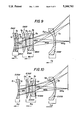
- FIG. 5 illustrates the fifth embodiment of the present invention corresponding to the fourth species of the invention.
- the front optical unit A 5 has a single negative element E502, and the third optical unit C 5 consists of a single negative meniscus lens element E532.
- the second optical unit B 5 is different from the construction of the optical unit B 1 in the first embodiment. While the second optical unit B 1 of the first embodiment was not color corrected, the second optical unit B 5 of the fifth embodiment is color corrected.
- the second optical unit B 5 comprises a doublet component and consists of a biconvex lens element E522 and a negative meniscus lens element E524. Again, as in first embodiment, all of the lens elements are made of plastic.
- the zooming motion of the front optical unit compared to the second optical unit B5 is quite small, therefore it may be possible to combine the two units for focusing. This would leave only two groups for the zooming system.
- Tables 5A through 5C give the important parameters of the fifth embodiment.
- the ratio of the extreme focal length in the sixth embodiment is 1.7:1 which qualifies the magnification range as 2:1.
- the F1 number changes from f/6.9 to f/4.55.
- FIG. 6 further illustrates the fourth species of the present invention. It corresponds to the sixth illustrative embodiment.
- the lens system of the sixth embodiment shown in FIG. 6 is similar to the lens system of the fifth embodiment shown in FIG. 5.
- the second, positive unit B 6 of sixth embodiment is also in the form of a doublet.
- the doublet takes a form of a positive biconvex lens element E622 and a negative biconcave lens element E624.
- the relative size and form of corresponding elements in a second optical unit differ between the fifth and the sixth embodiments for example the lens embodiments comprising the second optical unit of the sixth embodiment are larger in diameter than those of the fifth embodiment.
- Tables 6A through 6C give the important parameters of the sixth illustrative embodiment.
- FIG. 7 corresponds to the seventh illustrative embodiment. This embodiment is very similar to the fifth and sixth illustrative embodiments illustrated in FIGS. 5 and 6. Because these embodiments are very similar, further description will not be given, and for understanding of the seventh embodiment, reference is directed to the description of the fifth embodiment herein. Tables 7A through 7C give important parameters of the seventh embodiment.
- FIG. 8 illustrates the eighth embodiment of the present invention and corresponds to the fifth species of the invention.
- Table 8 gives values for various parameters describing the eighth embodiment.
- the first optical unit A 8 and the last optical unit C 8 of the eighth embodiment are similar to those of the first embodiment, A 1 and C 1 .
- the second optical unit B 8 of the eighth embodiment is different from the second optical unit B 1 of the first embodiment.
- the second optical unit B 1 of the first embodiment was not color corrected.
- the second optical unit of the fifth embodiment is color corrected.
- the second optical unit B 1 of the first embodiment consists of a single positive lens element.
- the second optical unit B 8 consists of two positive lens components-a single positive lens element E822 and a cemented doublet.
- the cemented doublet consists of a biconcave lens element E824 and a negative biconcave lens element E826 cemented to it.
- Tables 8A-8C give values for various parameters describing the eighth embodiment.
- Illustrative embodiments numbers nine through sixteen are very similar to the eighth illustrative embodiment and are shown in FIGS. 9-13. Tables 9 through 16 provide the important parameters for the above-mentioned embodiments.
- the lens system design represented by Tables 9A and 9B is a 1.4 ⁇ zoom lens.
- This lens system corresponding to the ninth embodiment has six lens elements arranged into three optical units.
- the first optical unit A 9 contains two negative meniscus lens elements E902 and E904.
- the concave surface of the lens elements E902 and E904 are oriented towards the object side.
- the first optical unit A 9 is followed by a second optical unit B 9 .
- the optical unit B 9 is color corrected and contains two lens components.
- the first lens component of the second optical unit B 9 is a biconvex lens element E922, the second optical component is a cemented doublet. It consists of a biconvex lens element E924 cemented to a meniscus lens element E926.
- the second optical unit B 9 is followed by a third optical unit C 9 .
- the third optical unit C 9 contains a single negative meniscus lens element E932, oriented with its concave surface towards the object side.
- This design is of the type where the aperture stop is positioned stationary relative to the image plane between the second zooming optical unit B 9 and the third zooming optical unit C 9 .
- the F-number varies from F/6.2 at the wide angle to F/5.8 at the longest focal length. Since the variation of the lens speed with zooming is so small, it can probably be assumed that for all the practical purposes the maximum F-number of the lens is constant. Consequently, one of the advantages of a camera utilizing this design is that the exposure determination can be done in a very simple fashion. Since the maximum speed of the lens at the wide angle is only F/6, the correction of the spherical aberation is easily achieved. The astigmatism and the tangential field are corrected by using an asphere on the rear element of the lens system.
- FIG. 10 illustrates the tenth embodiment. This embodiment is similar to the ninth embodiment described above with one exception, it has only five lens elements instead of six. In addition the rearmost lens element has an aspheric surface to facilitate the correction of aberrations.
- Tables 11A through 11B provide the numerical data for the lens system corresponding to the eleventh illustrative embodiment.
- the lens system has six glass elements and its focal length ranges between 29 and 39 mm.
- the configuration is very similar to the lens system configuration of the ninth embodiment in terms of number of lens elements, their shapes and their arrangement into the optical units.
- the aperture stop moves with the second zoom group and the diameter of the aperture stop is maintained at constant value.
- the maximum f-number of this lens system varies from F/4.5 at the wide angle to f/5.6 at the longest focal length. This lens system contains no aspherical surfaces.
- the twelfth illustrative embodiment illustrated on FIG. 12 and represented by Tables 12A through 12C is very similar to the eleventh illustrative embodiment. It has the same number of lens elements, the lens elements are shaped similarly and their arrangements into optical units are similar to that of the eleventh embodiment. As in the tenth embodiment, the aperture stop moves with the second optical unit and its diameter is maintained constant.
- the only significant difference between the eleventh and twelfth illustrative embodiment is that the twelfth embodiment has five glass and one plastic lens element.
- the plastic lens element is a rear lens element. One of the surfaces of the rear lens element is aspherical to fascilitate the correction of aberations.
- FIG. 13 illustrates the thirteenth embodiment of the present invention.
- Tables 13-A and 13-B provide important parameters of the lens system of this embodiment.
- the thirteenth embodiment is a five lens element, 1.4 zoom lens system.
- the F-number of the lens system varies from F/4.5 to F/5.6, and the focal length varies between 38 to 55 mm.
- This lens system has an internal focusing, i.e., focusing is accomplished by moving the first element of the second optical unit towards the film plane.
- the fourteenth illustrative embodiment, shown in FIG. 14 is similar to the thirteenth embodiment.
- Tables 14a and 14b provide the important data.
- the lens system of the fourteenth embodiment includes a front, negative power optical unit A14 movable for zooming, a second optical unit B14 of positive power movable for zooming and a third optical unit C14 of negative power also movable for zooming.
- the front optical unit A14 consists of a single biconcave lens element E1402.
- the second optical unit consists of two subunits, front and rear respectively.
- the front subunit is a single positive biconvex lens element E1422.
- the front subunit moves towards the film plane for focusing.
- the rear subunit is a cemented doublet component. It consists of a biconvex positive lens element E1424 cemented to a biconcave lens element E1426. Both subunits move forward for zooming.
- the third optical unit has two lens components--a front component is a negative meniscus lens element E1432 and the rear component is a positive biconvex lens element E1434.
- FIG. 15 illustrates that the lens system has five elements E1502 through E1532, arranged in three optical units A 15 , B 15 , and C 15 .
- This lens system has four glass and one plastic lens elements.
- the plastic lens element has an aspheric surface. As in the previous embodiment, all three optical units move differentially during zooming, and one of the subunits of the second optical unit is moved for focusing.
- embodiment number 16 is very similar to the 14th embodiment, i.e., elements type, their form and their arrangement in optical units is the same as the elements to which they correspond in the fourteenth embodiment illustrated in FIG. 14, and since A is also similar to the fifteenth embodiment described herein, further description will not be given, an understanding of this embodiment, reference is directed to the description of the fourteenth and fifteenth embodiment herein.
- FIG. 17 illustrates the sixth species of the invention and corresponds to the seventeenth embodiment of the present invention.
- the sixth species of the present invention are similar to the fourth species, the only difference, being that glass was used instead of plastic and fewer aspheres were utilized.
- the ratio of powers of the first optical and to the third optical unit is 0.74.
- Tables 17A-C provides important parameters of the embodiment illustrated in FIG. 17.
Landscapes
- Physics & Mathematics (AREA)
- General Physics & Mathematics (AREA)
- Optics & Photonics (AREA)
- Lenses (AREA)
Abstract
Description
              TABLE 1-A
______________________________________
        VERTEX    THICK-            CLEAR
SURFACE RADIUS    NESS     GLASS    APERTURE
______________________________________
S1      -15.32    1.300    KPOLYSTY  9.8
S2       717.58   VAS.sub.1          9.7
S3       20.98    4.229    ACRYLIC  10.3
S4      -12.44    3.145             11.1
        ∞   2.614              9.7
        ∞   VAS.sub.2         10.0
S5      -11.92    1.900    KPUV     18.1
S6      -28.44    VAS.sub.3         22.2
        ∞   11.017            31.3
______________________________________
              TABLE 1-B
______________________________________
POLYNOMIAL ASPHERS
(COEFFICIENTS OF THE EVEN POWERED TERMS)
______________________________________
SURFACE   AD (4TH)    AE (6TH)  AF (8TH)
______________________________________
S1         4.897E-06   1.314E-08
                                2.788E-08
S2        -9.649E-05  -8.153E-08
                                9.231E-08
S3        -3.517E-04  -2.120E-06
                                -2.737E-07
S4        -1.248E-04  -2.725E-06
                                -1.316E-07
S6         1.448E-05  -2.657E-08
                                5.805E-12
______________________________________
SURFACE   AG (10th)   AH (12TH) AI (14TH)
______________________________________
S1        -1.214E-10  -2.570E-11
                                4.017E-13
S2        -2.214E-09  -6.570E-11
                                2.049E-12
S3         5.549E-10   2.859E-10
                                -1.156E-11
S4         1.831E-10   5.158E-11
                                -2.092E-12
S6         6.227E-14  -1.120E-14
                                6.029E-17
______________________________________
              TABLE 1-C
______________________________________
ZOOM SPACING DATA
POSITION
        VAS.sub.1  VAS.sub.1
                           VAS.sub.2
                                   EFL  F/#
______________________________________
1       3.164      19.699
.019                               38.02
                                        4.6
2       2.338      15.034  12.062  50.01
                                        5.8
3       1.597      11.612  28.960  65.21
                                        7.3
______________________________________
              TABLE 2-A
______________________________________
                  THICK-            CLEAR
SURFACE RADIUS    NESS     GLASS    APERTURE
______________________________________
S1      -18.804   1.300    KPOLYSTY 17.9
S2      117.174   VAS.sub.1         17.5
S3      16.353    3.900    ACRYLIC  16.1
S4      -34.328    .570             15.6
S5      44.251    3.400    ACRYLIC  13.7
S6      -55.618   VAS.sub.2         11.9
        ∞   14.840             7.7
S7      -9.801    1.930    ACRYLIC  16.7
S8      -24.687   11.097            22.0
______________________________________
              TABLE 2-B
______________________________________
POLYNOMIAL ASPHERS
(COEFFICIENTS OF THE EVEN POWERED TERMS)
______________________________________
SURFACE   AD (4TH)    AE (6TH)  AF (8TH)
______________________________________
S2        -3.745E-05  -2.177E-07
                                 2.162E-09
S3        -8.042E-05  -3.442E-07
                                -3.732E-10
S6         2.698E-05  -8.546E-07
                                 1.232E-08
S8        -1.592E-05   5.291E-07
                                -8.063E-09
______________________________________
SURFACE   AG (10TH)   AH (12TH) AI (14TH)
______________________________________
S2        -4.515E-12  -1.463E-13
                                 3.018E-16
S3         1.163E-11   3.655E-13
                                -6.877E-15
S6         5.410E-12  -5.623E-12
                                 6.274E-14
8S         9.649E-12   5.651E-13
                                -3.282E-15
______________________________________
              TABLE 2-C
______________________________________
ZOOM SPACING DATA
POSITION
        VAS.sub.1  VAS.sub.2
                           BFL     EFL  F/#
______________________________________
1       2.882      13.935  11.0983 38.80
                                        4.4
2       1.709      11.205  20.4615 50.08
                                        5.6
3       .400       8.840   34.897  68.58
                                        7.2
______________________________________
              TABLE 3-A
______________________________________
                  THICK-   OPTICAL  CLEAR
SURFACE RADIUS    NESS     MATERIAL APERTURE
______________________________________
S1      43.603    1.500    KPOLYSTY 14.4
S2      25.305    2.408             13.8
S3      -21.027   1.300    KPUV     13.8
S4      37,822    VAS.sub.1         14.3
S5      14.122    3.900    KACRYLIC 14.4
S6      -34.544    .149             14.5
S7      38.447    3.400    KACRYLIC 14.3
S8      -44.390   4.505             13.9
        ∞   VAS.sub.2         10.4
S9      -8.580    1.930    KACRYLIC 14.6
 S10    -14.985   63.225            18.3
______________________________________
              TABLE 3-B
______________________________________
POLYNOMIAL ASPHERS
(COEFFICIENTS OF THE EVEN POWERED TERMS)
______________________________________
SURFACE   AD (4TH)    AE (6TH)  AF (8TH)
______________________________________
S1        -1.877E-05  -1.303E-07
                                -7.509E-10
S4        -1.066E-04  -4.836E-07
                                 2.081E-09
S5        -1.790E-04  -7.582E-07
                                -4.329E-09
S8        -2.344E-05  -1.263E-06
                                 6.102E-09
 S10       3.162E-07   3.960E-07
                                -9.166E-09
______________________________________
SURFACE   AG (10TH)   AH (12TH) AI (14TH)
______________________________________
S1        -2.246E-12  -7.946E-14
                                -5.693E-15
S4        -6.140E-11  -1.798E-12
                                -2.293E-14
S5        -2.996E-11  -8.389E-13
                                -5.785E-14
S8        -3.576E-11  -6.482E-12
                                 8.306E-14
 S10       4.786E-11   7.227E.13
                                -7.425E-15
______________________________________
              TABLE 3-C
______________________________________
ZOOM SPACING DATA
POSITION         VAS.sub.1
                         VAS.sub.2
______________________________________
1                3.056   14.288
2                .999    9.179
3                .400    7.931
______________________________________
              TABLE4-A
______________________________________
                  THICK-            CLEAR
SURFACE RADIUS    NESS     GLASS    APERTURE
______________________________________
S1      -18.263   1.800    KPOLYSTY 12.4
S2      85.945    VAS.sub.1         11.8
S3      14.408    4.100    ACRYLIC  10.6
S4      -15.033   5.557             10.8
        ∞   2.614             8.6
        ∞   VAS.sub.2         9.5
S5      -9.976    1.900    KPUV     15.4
S6      -27.393   VAS.sub.3         19.7
S7      -42.700   3.000    F5       28.8
S8      -80.643   10.880            30.0
______________________________________
              TABLE 4-B
______________________________________
POLYNOMIAL ASPHERS
(COEFFICIENTS OF THE EVEN POWERED TERMS)
______________________________________
SURFACE   AD (4TH)    AE (6TH)  AF (8TH)
______________________________________
S2        -6.841E-05  1.856E-06 -4.992E-08
S3        -1.888E-04  -1.638E-07
                                -1.152E-07
S4        -3.319E-05  -1.008E-06
                                -1.047E-07
S6         1.880E-05  -1.166E-07
                                 2.649E-09
______________________________________
SURFACE   AG (10TH)   AH (12TH) AF (14TH)
______________________________________
S2        -1.929E-10  4.135E-11 -6.148E-13
S3        -1.416E-09  1.221E-10 -3.332E-12
S4        -5.438E-11  4.885E-11 -1.466E-12
S6        -4.993E-11  3.791E-13 -1.053E-15
______________________________________
              TABLE 4-C
______________________________________
ZOOM SPACING DATA
POSITION
        VAS.sub.1  VAS.sub.2
                           VAS.sub.3
                                   EFL  F/#
______________________________________
1       3.278      13.017  .600    38.004
                                        4.4
2       1.885      11.380  9.010   49.998
                                        5.6
3        .817      10.002  22.032  66.284
                                        7.2
______________________________________
              TABLE 5-A
______________________________________
                  THICK-            CLEAR
SURFACE RADIUS    NESS      GLASS   APERTURE
______________________________________
S1      -33.479   1.300     ACRYLIC 18.4
S2      70.626    VAS.sub.1         17.2
S3      14.339    4.300     ACRYLIC 11.7
S4      -12.411    .037             10.9
S5      -12.102   2.315     591307  10.9
S6      -27.966   4.810             10.4
        ∞   2.614             8.8
        ∞   VAS.sub.2         9.5
S7      -9.498    3.159     ACRYLIC 16.7
S8      -17.758   31.850            21.9
______________________________________
              TABLE 5-B
______________________________________
POLYNOMIAL ASPHERS
(COEFFICIENTS OF THE EVEN POWERED TERMS)
______________________________________
SURFACE   AD (4TH)    AE (6TH)   AF (8TH)
______________________________________
S2        -1.200E-05  3.248E-08  9.423E-11
S3         2.159E-05  2.531E-07  -3.548E-10
S6         2.702E-05  -7.391E-07 4.572E-08
S8        -8.310E-06  -2.038E-07 2.104E-09
______________________________________
SURFACE   AG (10TH)   AH (12TH)  AF (14TH)
______________________________________
S2        -3.066E-11  6.035E-13  -3.432E-15
S3         1.236E-10  1.171E-12  5.420E-14
S6        -1.343E-09  3.069E-11  -2.479E-13
S8        -1.512E-11  4.339E-15  3.746E-17
______________________________________
              TABLE 5-C
______________________________________
ZOOM SPACING DATA
POSITION
        VAS.sub.1  VAS.sub.2
                           BFL     EFL  F/#
______________________________________
1       10.896     16.600  10.55   37.84
                                        4.5
2       5.982      14.341  19.62   50.00
                                        5.5
3       2.004      12.736  30.28   65.55
                                        6.9
______________________________________
              TABLE 6-A
______________________________________
                  THICK-   OPTICAL  CLEAR
SURFACE RADIUS    NESS     MATERIAL APERTURE
______________________________________
S1      -37.78    1.800    591307   23.0
S2      147.99    VAS.sub.1         21.9
S3      10.72     6.198    ACRYLIC  16.2
S4      -45.24     .232             14.4
S5      -57.62    1.624    591307   13.4
S6      191.77     .000             11.3
        ∞   6.067             11.6
        ∞   VAS.sub.2          7.4
S7      -10.89    1.673    ACRYLIC  16.3
S8      -27.01    27.992            20.3
______________________________________
              TABLE 6-B
______________________________________
POLYNOMIAL ASPHERS
(COEFFICIENTS OF THE EVEN POWERED TERMS)
______________________________________
SURFACE   AD (4TH)    AE (6TH)  AF (8TH)
______________________________________
S3         1.156E-04   5.922E-07
                                2.566E-09
S6         1.510E-04   1.162E-06
                                3.713E-08
S8        -5.978E-07  -1.705E-07
                                2.776E-09
______________________________________
SURFACE   AG (10TH)   AH (12TH) AF (14TH)
______________________________________
S3         2.012E-10  -2.724E-12
                                2.023E-14
S6        -2.024E-09   7.949E-11
                                -1.025E-12
S8        -1.766E-11  -2.943E-14
                                4.735E-16
______________________________________
              TABLE 6-C
______________________________________
ZOOM SPACING DATA
POSITION  VAS.sub.1 VAS.sub.2
                            BFL    EFL   F/#
______________________________________
1         11.553    14.658  10.55  37.70 4.6
2         5.898     13.171  17.69  50.00 5.5
3         1.812     11.844  26.43  65.14 6.9
______________________________________
              TABLE 7-A
______________________________________
                  THICK-            CLEAR
SURFACE RADIUS    NESS     GLASS    APERTURE
______________________________________
S1      -39.892   1.800    ACRYLIC  23.9
S2      92.587    VAS.sub.1         22.3
S3      14.158    6.200    ACRYLIC  15.5
S4      -15.103    .036             15.5
S5      -14.886   3.590    591307   15.5
S6      -48.353    .000             15.5
        ∞   4.856             10.0
        ∞   VAS.sub.2          8.5
S7      -10.923   1.670    ACRYLIC  19.2
S8      -21.623   29.607            23.8
______________________________________
              TABLE 7-B
______________________________________
POLYNOMIAL ASPHERS
(COEFFICIENTS OF THE EVEN POWERED TERMS)
______________________________________
SURFACE   AD (4TH)    AE (6TH)  AF (8TH)
______________________________________
S2        -5.142E-06  -8.010E-08
                                2.796E-09
S3         4.428E-05  -5.124E-08
                                5.275E-09
S6         4.575E-05  -6.689E-07
                                5.842E-08
S8        -1.209E-06  -4.207E-07
                                4.878E-09
______________________________________
SURFACE   AG (10TH)   AH (12TH) AF (14TH)
______________________________________
S2        -4.484E-11   3.262E-13
                                -8.798E-16
S3         1.542E-10  -5.361E-12
                                5.166E-14
S6        -2.502E-09   6.113E-11
                                -6.073E-13
S8        -1.566E-11  -1.087E-13
                                5.703E-16
______________________________________
              TABLE 7-C
______________________________________
ZOOM SPACING DATA
POSITION  VAS.sub.1 VAS.sub.2
                            BFL    EFL   F/#
______________________________________
1         15.938    20.160  11.003 38.799
                                         4.55
2         10.030    17.851  19.013 49.989
                                         5.50
3          3.290    16.499  29.607 68.613
                                         6.90
______________________________________
              TABLE 8-A
______________________________________
                    THICK-           CLEAR
SURFACE RADIUS      NESS      GLASS  APERTURE
______________________________________
S1      -51.163     1.700     NBFD11 26.3
S2       146.318    VAS.sub.1        25.4
S3      -34.987     3.769     LAC12  21.4
S4      -17115.910  13.982           20.5
S5       14.296     4.939     BSC7   10.3
S6      -14.296     1.000     FL7    9.3
S7       92.255     1.876            8.9
        ∞     1.614            8.3
        ∞     VAS.sub.2        7.9
S8       -8.671     1.900     FC5    15.0
S9      -15.783     35.010           19.0
______________________________________
              TABLE 8-B
______________________________________
ZOOM SPACING DATA
POSITION  VAS.sub.1 VAS.sub.2
                            BFL    EFL   F/#
______________________________________
1         12.341    12.939  15.403 38.804
                                         4.60
2         6.662     11.611  23.357 50.006
                                         5.60
3         .590      10.869  35.010 68.638
                                         7.20
______________________________________
              TABLE 9-A
______________________________________
                  THICK-            CLEAR
SURFACE RADIUS    NESS     GLASS    APERTURE
______________________________________
S1      -19.489   1.000    NBFD10   15.8
S2      -57.315   1.100             15.7
S3      -16.491   1.000    FC5      15.8
S4      -54.054   VAS.sub.1         16.1
S5      46.985    2.700    F8       16.4
S6      -19.197    .200             16.4
S7      15.360    3.000    BSC7     13.4
S8      -16.215   2.500    FD6      13.4
S9      -53.873   VAS.sub.2         11.6
        ∞   VAS.sub.3         6.1
 S10    -10.944   1.200    ACRYLIC  14.8
 S11    -30.947   VAS.sub.4         18.8
        ∞   5.001             33.1
______________________________________
              TABLE 9-B
______________________________________
POLYNOMIAL ASPHERS
(COEFFICIENTS OF THE EVEN POWERED TERMS)
SURFACE  AD (4TH)  AE (6TH)  AF (8TH)
                                     AG (10TH)
______________________________________
10       -8.197E-05
                   -1.149E-06
                             6.871E-09
                                     2.958E-10
______________________________________
              TABLE 9-C
______________________________________
ZOOM SPACING DATA
POSITION VAS.sub.1
                 VAS.sub.2
                         VAS.sub.3
                               VAS.sub.4
                                     EFL   F/#
______________________________________
1        3.063    .276   15.800
                                6.000
                                     29.000
                                           6.2
2        2.039   7.690    4.854
                               16.946
                                     38.606
                                           5.8
3        2.541   3.119   11.377
                               10.423
                                     33.002
                                           6.3
______________________________________
              TABLE 10-A
______________________________________
                  THICK-            CLEAR
SURFACE RADIUS    NESS     GLASS    APERTURE
______________________________________
S1      -18.012   1.000    TAF3     15.5
S2      474.104   VAS.sub.1         15.4
S3      58.005    2.700    FL7      15.3
S4      -19.016    .200             15.3
S5      13.636    3.000    FC5      12.6
S6      -20.931   2.500    FD6      12.1
S7      -104.385  VAS.sub.2         10.3
        ∞   VAS.sub.3         6.4
S8      -10.036   1.200    ACRYLIC  14.8
S9      -23.395   VAS.sub.4         18.9
        ∞   4.999             33.7
______________________________________
              TABLE 10-B
______________________________________
POLYNOMIAL ASPHERS
(COEFFICIENTS OF THE EVEN POWERED TERMS)
______________________________________
SURFACE   AD (4TH)    AE (6TH)  AF (8TH)
______________________________________
S8        -9.612E-05  -1.974E-06
                                3.889E-08
______________________________________
SURFACE
NO.       AG (10TH)   AH (12TH) AI (14TH)
______________________________________
S8        -7.506E-10   0.000E+00
                                0.000E+00
______________________________________
              TABLE 10-C
______________________________________
ZOOM SPACING DATA
POSI-
TION   VAS.sub.1
               VAS.sub.2
                        VAS.sub.3
                              VAS.sub.4
                                     EFL   F/#
______________________________________
1      5.906    .137    16.800
                               6.000 28.100
                                           6.20
2      4.562   7.453     6.262
                              16.538 38.598
                                           5.79
3      5.267   2.985    12.412
                              10.389 32.999
                                           6.30
______________________________________
              TABLE 11-A
______________________________________
                                    CLEAR
SURFACE RADIUS   THICKNESS   GLASS  APERTURE
______________________________________
S1      -25.413  1.000       LACL6  12.9
S2      539.321  1.100              12.0
S3      -18.363  1.000       FC5    12.0
S4      172.107  VAS.sub.1          11.5
S5      29.116   1.933       BSC7   10.9
S6      -17.823   .200              10.8
S7      12.308   2.600       BACD5  9.2
S8      -14.030  5.440       NBFD10 8.4
S9      -83.692   .392              6.8
 S10    ∞  VAS.sub.2          7.1
 S11    -6.747   1.200       FC5    12.7
 S12    -12.213  VAS.sub.3          16.6
 S13    ∞  5.003              34.2
______________________________________
              TABLE 11-B
______________________________________
ZOOM SPACING DATA
POSITION VAS.sub.1
                  VAS.sub.2
                           VAS.sub.3
                                  EFL    F/#
______________________________________
1        1.785    11.865    6.572 29.003 4.60
2         .587    10.283   14.819 38.607 5.79
3        1.209    11.114   10.049 33.004 5.11
______________________________________
              TABLE 12-A
______________________________________
                  THICK-            CLEAR
SURFACE RADIUS    NESS     GLASS    APERTURE
______________________________________
S1      -23.281   1.000    LAC8     12.0
S2      -77.986   1.100             11.4
S3      -18.509   1.000    FC5      11.0
S4      125.143   VAS.sub.1         10.4
S5      66.113    1.933    BAF3     9.4
S6      -19.864    .200             9.0
S7      13.664    3.000    BSC7     8.2
S8      -13.716   2.500    FD6      7.6
S9      -32.071    .500             7.5
        ∞   VAS.sub.2         7.8
 S10    -7.949    1.200    ACRYLIC  14.6
 S11    -13.964   VAS.sub.3         18.5
        ∞   4.100             34.3
______________________________________
              TABLE 12-B
______________________________________
POLYNOMIAL ASPHERS
(COEFFICIENTS OF THE EVEN POWERED TERMS)
______________________________________
SURFACE
NO.       AD (4TH)     AE (6TH)  AF (8TH)
______________________________________
11        -1.575E-05   -3.731E-07
                                 0.000E+00
______________________________________
SURFACE
NO.       AG (10TH)    AH (12TH) AF (14TH)
______________________________________
11        0.000E+00    0.000E+00 0.000E+00
______________________________________
              TABLE 12-C
______________________________________
ZOOM SPACING DATA
POSITION   VAS.sub.1    VAS.sub.2
                                VAS.sub.3
______________________________________
1          2.351        15.657  6.000
2           .963        13.467  15.066
3          1.689        14.601  9.843
______________________________________
              TABLE 13-A
______________________________________
                   THICK-           CLEAR
SURFACE RADIUS     NESS     GLASS   APERTURE
______________________________________
S1      -25.300    1.300    LAC8    16.0
S2      ∞    VAS.sub.1        15.5
S3      -174.280   2.600    FC5     13.2
S4      -21.220    VAS.sub.2        12.8
S5      14.620     3.500    LACL6   10.7
S6      -23.770    1.000    NBFD10  10.1
S7      137.500    3.060            9.8
        ∞    VAS.sub.3        8.8
S8      -8.285     1.600    FC5     14.6
S9      -13.377    VAS.sub.4        17.8
        ∞    6.900            35.1
______________________________________
              TABLE 13-B
______________________________________
ZOOM SPACING DATA
POSITION VAS.sub.1
                 VAS.sub.2
                         VAS.sub.3
                               VAS.sub.4
                                     EFL   F/#
______________________________________
1        6.318   1.539   15.357
                               10.333
                                     39.000
                                           4.60
2        2.203   1.539   14.165
                               20.033
                                     53.000
                                           5.79
3        4.608   1.539   14.759
                               14.022
                                     44.000
                                           5.03
4        7.539    .311   15.357
                               10.333
                                     36.512
                                           4.43
5        3.510    .232   14.165
                               20.033
                                     48.507
                                           5.50
______________________________________
              TABLE 14-A
______________________________________
                                    CLEAR
SURFACE RADIUS   THICKNESS   GLASS  APERTURE
______________________________________
S1      -32.554  1.300       BAC05  19.6
S2      55.013   VAS.sub.1          18.4
S3      113.511  2.700       TAF1   16.1
S4      -31.761  VAS.sub.2          15.7
S5      12.136   3.700       FC5    11.7
S6      -29.225  1.000       FD2    10.3
S7      38.755   3.348              9.5
        ∞  VAS.sub.3          8.2
S8      -8.541   1.200       LAC8   15.4
S9      -14.147   .200              19.3
 S10    310.334  4.400       FL7    26.5
 S11    -48.348  VAS.sub.4          28.2
        ∞  6.909              35.3
______________________________________
              TABLE 14-B
______________________________________
POSI-
TION   VAS.sub.1
               VAS.sub.2
                        VAS.sub.3
                              VAS.sub.4
                                     EFL   F/#
______________________________________
1      7.228   1.558    15.366
                               4.100 36.201
                                           4.5
2      1.913   1.558    13.534
                              16.614 53.005
                                           5.8
3      8.559    .227    15.366
                               4.100 33.534
                                           4.3
4      3.252    .227    13.534
                              16.614 47.794
                                           5.5
5      4.362   1.558    14.109
                              10.378 44.010
                                           5.1
______________________________________
              TABLE 15-A
______________________________________
                                    CLEAR
SURFACE RADIUS   THICKNESS   GLASS  APERTURE
______________________________________
S1      -21.860  1.300       TAF1   15.4
S2      -231.770 VAS.sub.1          14.9
S3      -4330.810
                 2.700       CF6    12.3
S4      -21.296   .200              11.8
S5      18.105   3.400       BAC4   10.5
S6      -20.362  1.000       FD1    10.1
S7      -259.226 1.000              9.8
        ∞  VAS.sub.2          9.5
S8      -10.849  1.600       ACRYLIC
                                    18.6
S9      -21.349  VAS.sub.3          23.1
 S10    ∞  6.898              34.8
______________________________________
              TABLE 15-B
______________________________________
POLYNOMIAL ASPHERS
(COEFFICIENTS OF THE EVEN POWERED TERMS)
______________________________________
SURFACE
NO.       AD (4TH)     AE (6TH)  AF (8TH)
______________________________________
S8        -1.767E-05   -8.812E-08
                                 -1.331E-09
______________________________________
SURFACE
NO.       AG (10TH)    AH (12TH) AI (14TH)
______________________________________
S9         1.097E-11   -1.726E-13
                                  1.309E-15
______________________________________
              TABLE 15-C
______________________________________
ZOOM SPACING DATA
POSITION VAS.sub.1
                  VAS.sub.2
                           VAS.sub.3
                                  EFL    F/#
______________________________________
1        7.193    23.607    4.100 36.215 4.53
2        3.896    19.716   18.940 53.012 6.20
3        5.393    21.479   11.079 44.008 5.30
______________________________________
              TBALE 16-A
______________________________________
                                    CLEAR
SURFACE RADIUS   THICKNESS   GLASS  APERTURE
______________________________________
S1      -35.148  1.300       PCD2   22.3
S2      61.193   VAS.sub.1          20.8
S3      75.049   3.600       F5     18.2
S4      -31.097  VAS.sub.2          17.6
S5      11.907   4.000       PCD2   12.4
S6      -32.563  1.000       FD13   10.3
S7      32.563   2.402              8.8
        ∞  VAS.sub.3          7.7
S8      -7.833   1.200       LAC14  14.4
S9      -13.430   .200              18.6
 S10    1405.963 3.800       FD1    26.1
 S11    -52.074  VAS.sub.4          27.7
        ∞  6.895              34.8
______________________________________
              TABLE 16-B
______________________________________
ZOOM SPACING DATA
POSITION   VAS.sub.1
                   VAS.sub.2  VAS.sub.3
                                    VAS.sub.4
______________________________________
1          7.320   1.908      13.758
                                     5.613
2           .945   1.908      12.554
                                    16.458
3          9.001    .227      13.758
                                     5.613
4          2.598    .227      12.554
                                    16.458
5          3.857   1.908      12.947
                                    10.940
______________________________________
              TABLE 17-A
______________________________________
                                    CLEAR
SURFACE RADIUS   THICKNESS   GLASS  APERTURE
______________________________________
S1      -66.552  2.000       FC5    24.7
S2      59.653   VAS.sub.1          22.6
S3      15.733   5.000       CF6    8.9
S4      -12.148  1.000       FD15   8.2
S5      -35.063  1.809              8.2
        ∞  2.614              7.7
S6      ∞  VAS.sub.2          7.1
S7      -9.251   1.900       FC5    15.5
S8      -16.393  32.448             19.0
______________________________________
              TABLE 17-B
______________________________________
ZOOM SPACING DATA
POSITION         VAS.sub.1
                         VAS.sub.2
______________________________________
1                26.462  17.149
2                16.958  16.107
3                10.480  15.429
______________________________________
Claims (43)
Priority Applications (4)
| Application Number | Priority Date | Filing Date | Title |
|---|---|---|---|
| US07/702,862 US5268792A (en) | 1991-05-20 | 1991-05-20 | Zoom lens |
| JP93500158A JPH05508945A (en) | 1991-05-20 | 1992-05-14 | zoom lens |
| PCT/US1992/003980 WO1992021048A1 (en) | 1991-05-20 | 1992-05-14 | A zoom lens |
| GB9300872A GB2261529B (en) | 1991-05-20 | 1993-01-18 | A zoom lens |
Applications Claiming Priority (1)
| Application Number | Priority Date | Filing Date | Title |
|---|---|---|---|
| US07/702,862 US5268792A (en) | 1991-05-20 | 1991-05-20 | Zoom lens |
Publications (1)
| Publication Number | Publication Date |
|---|---|
| US5268792A true US5268792A (en) | 1993-12-07 |
Family
ID=24822897
Family Applications (1)
| Application Number | Title | Priority Date | Filing Date |
|---|---|---|---|
| US07/702,862 Expired - Lifetime US5268792A (en) | 1991-05-20 | 1991-05-20 | Zoom lens |
Country Status (3)
| Country | Link |
|---|---|
| US (1) | US5268792A (en) |
| GB (1) | GB2261529B (en) |
| WO (1) | WO1992021048A1 (en) |
Cited By (56)
| Publication number | Priority date | Publication date | Assignee | Title |
|---|---|---|---|---|
| WO1996019749A1 (en) * | 1994-12-19 | 1996-06-27 | Benopcon, Inc. | Variable power lens systems for producing small images |
| US5602676A (en) * | 1994-11-30 | 1997-02-11 | Eastman Kodak Company | Compact zoom lens with reduced aspheric decenter sensitivity |
| US5604637A (en) * | 1995-04-17 | 1997-02-18 | Eastman Kodak Company | Zoom lens |
| US5642231A (en) * | 1994-11-30 | 1997-06-24 | Eastman Kodak Company | Compact 3X zoom lens |
| US5644434A (en) * | 1994-05-16 | 1997-07-01 | Minolata Co. Ltd. | Zoom lens system |
| US5726799A (en) * | 1993-07-12 | 1998-03-10 | Asahi Kogaku Kogyo Kabushiki Kaisha | Real image type viewfinder |
| US6018425A (en) * | 1996-09-30 | 2000-01-25 | Ishihara | Wide-angle lens assembly and method |
| US6028716A (en) * | 1993-11-29 | 2000-02-22 | Canon Kabushiki Kaisha | Zoom lens |
| US6160669A (en) * | 1996-04-15 | 2000-12-12 | Olympus Optical Co., Ltd. | Lens system |
| US6721107B2 (en) * | 2001-01-24 | 2004-04-13 | Pentax Corporation | Zoom lens system |
| WO2004044638A1 (en) * | 2002-11-11 | 2004-05-27 | Koninklijke Philips Electronics N.V. | Zoom lens |
| US20060082900A1 (en) * | 2004-10-19 | 2006-04-20 | Canon Kabushiki Kaisha | Zoom lens and imaging apparatus having the same |
| US20070070495A1 (en) * | 2005-09-26 | 2007-03-29 | Konica Minolta Opto, Inc. | Zoom lens |
| CN100417968C (en) * | 2002-10-08 | 2008-09-10 | 索尼株式会社 | Imaging lens |
| US10089516B2 (en) | 2013-07-31 | 2018-10-02 | Digilens, Inc. | Method and apparatus for contact image sensing |
| US10145533B2 (en) | 2005-11-11 | 2018-12-04 | Digilens, Inc. | Compact holographic illumination device |
| US10156681B2 (en) | 2015-02-12 | 2018-12-18 | Digilens Inc. | Waveguide grating device |
| US10185154B2 (en) | 2011-04-07 | 2019-01-22 | Digilens, Inc. | Laser despeckler based on angular diversity |
| US10209517B2 (en) | 2013-05-20 | 2019-02-19 | Digilens, Inc. | Holographic waveguide eye tracker |
| US10216061B2 (en) | 2012-01-06 | 2019-02-26 | Digilens, Inc. | Contact image sensor using switchable bragg gratings |
| US10234696B2 (en) | 2007-07-26 | 2019-03-19 | Digilens, Inc. | Optical apparatus for recording a holographic device and method of recording |
| US10241330B2 (en) | 2014-09-19 | 2019-03-26 | Digilens, Inc. | Method and apparatus for generating input images for holographic waveguide displays |
| US10330777B2 (en) | 2015-01-20 | 2019-06-25 | Digilens Inc. | Holographic waveguide lidar |
| US10359736B2 (en) | 2014-08-08 | 2019-07-23 | Digilens Inc. | Method for holographic mastering and replication |
| US10423222B2 (en) | 2014-09-26 | 2019-09-24 | Digilens Inc. | Holographic waveguide optical tracker |
| US10437064B2 (en) | 2015-01-12 | 2019-10-08 | Digilens Inc. | Environmentally isolated waveguide display |
| US10437051B2 (en) | 2012-05-11 | 2019-10-08 | Digilens Inc. | Apparatus for eye tracking |
| US10459145B2 (en) | 2015-03-16 | 2019-10-29 | Digilens Inc. | Waveguide device incorporating a light pipe |
| US10545346B2 (en) | 2017-01-05 | 2020-01-28 | Digilens Inc. | Wearable heads up displays |
| US10591756B2 (en) | 2015-03-31 | 2020-03-17 | Digilens Inc. | Method and apparatus for contact image sensing |
| US10642058B2 (en) | 2011-08-24 | 2020-05-05 | Digilens Inc. | Wearable data display |
| US10670876B2 (en) | 2011-08-24 | 2020-06-02 | Digilens Inc. | Waveguide laser illuminator incorporating a despeckler |
| US10678053B2 (en) | 2009-04-27 | 2020-06-09 | Digilens Inc. | Diffractive projection apparatus |
| US10690851B2 (en) | 2018-03-16 | 2020-06-23 | Digilens Inc. | Holographic waveguides incorporating birefringence control and methods for their fabrication |
| US10690916B2 (en) | 2015-10-05 | 2020-06-23 | Digilens Inc. | Apparatus for providing waveguide displays with two-dimensional pupil expansion |
| US10732569B2 (en) | 2018-01-08 | 2020-08-04 | Digilens Inc. | Systems and methods for high-throughput recording of holographic gratings in waveguide cells |
| US10859768B2 (en) | 2016-03-24 | 2020-12-08 | Digilens Inc. | Method and apparatus for providing a polarization selective holographic waveguide device |
| US10890707B2 (en) | 2016-04-11 | 2021-01-12 | Digilens Inc. | Holographic waveguide apparatus for structured light projection |
| US10914950B2 (en) | 2018-01-08 | 2021-02-09 | Digilens Inc. | Waveguide architectures and related methods of manufacturing |
| US10942430B2 (en) | 2017-10-16 | 2021-03-09 | Digilens Inc. | Systems and methods for multiplying the image resolution of a pixelated display |
| US10983340B2 (en) | 2016-02-04 | 2021-04-20 | Digilens Inc. | Holographic waveguide optical tracker |
| US11204540B2 (en) | 2009-10-09 | 2021-12-21 | Digilens Inc. | Diffractive waveguide providing a retinal image |
| US11307432B2 (en) | 2014-08-08 | 2022-04-19 | Digilens Inc. | Waveguide laser illuminator incorporating a Despeckler |
| US11378732B2 (en) | 2019-03-12 | 2022-07-05 | DigLens Inc. | Holographic waveguide backlight and related methods of manufacturing |
| US11402801B2 (en) | 2018-07-25 | 2022-08-02 | Digilens Inc. | Systems and methods for fabricating a multilayer optical structure |
| US11442222B2 (en) | 2019-08-29 | 2022-09-13 | Digilens Inc. | Evacuated gratings and methods of manufacturing |
| US11448937B2 (en) | 2012-11-16 | 2022-09-20 | Digilens Inc. | Transparent waveguide display for tiling a display having plural optical powers using overlapping and offset FOV tiles |
| US11460621B2 (en) | 2012-04-25 | 2022-10-04 | Rockwell Collins, Inc. | Holographic wide angle display |
| US11480788B2 (en) | 2015-01-12 | 2022-10-25 | Digilens Inc. | Light field displays incorporating holographic waveguides |
| US11513350B2 (en) | 2016-12-02 | 2022-11-29 | Digilens Inc. | Waveguide device with uniform output illumination |
| US11543594B2 (en) | 2019-02-15 | 2023-01-03 | Digilens Inc. | Methods and apparatuses for providing a holographic waveguide display using integrated gratings |
| US11630289B2 (en) | 2020-09-09 | 2023-04-18 | Largan Precision Co., Ltd. | Image capturing lens system, image capturing unit and electronic device |
| US11681143B2 (en) | 2019-07-29 | 2023-06-20 | Digilens Inc. | Methods and apparatus for multiplying the image resolution and field-of-view of a pixelated display |
| US11726332B2 (en) | 2009-04-27 | 2023-08-15 | Digilens Inc. | Diffractive projection apparatus |
| US11747568B2 (en) | 2019-06-07 | 2023-09-05 | Digilens Inc. | Waveguides incorporating transmissive and reflective gratings and related methods of manufacturing |
| US12092914B2 (en) | 2018-01-08 | 2024-09-17 | Digilens Inc. | Systems and methods for manufacturing waveguide cells |
Families Citing this family (3)
| Publication number | Priority date | Publication date | Assignee | Title |
|---|---|---|---|---|
| GB2282461A (en) * | 1991-11-25 | 1995-04-05 | Asahi Optical Co Ltd | Variable power view finder |
| US5410430A (en) * | 1991-11-25 | 1995-04-25 | Asahi Kogaku Kogyo Kabushiki Kaisha | Variable power view finder |
| JP3365837B2 (en) * | 1993-10-26 | 2003-01-14 | オリンパス光学工業株式会社 | Focusing method of 3-group zoom lens |
Citations (22)
| Publication number | Priority date | Publication date | Assignee | Title |
|---|---|---|---|---|
| US4198128A (en) * | 1977-01-21 | 1980-04-15 | Minolta Camera Kabushiki Kaisha | Wide angle zoom lens system |
| US4571031A (en) * | 1982-02-01 | 1986-02-18 | Canon Kabushiki Kaisha | Wide angle zoom objective |
| US4682860A (en) * | 1980-03-14 | 1987-07-28 | Canon Kabushiki Kaisha | Ultrasmall size zoom lens |
| US4720179A (en) * | 1985-11-28 | 1988-01-19 | Asahi Kogaku Kogyo Kabushiki Kaisha | Zoom lens system for use with a compact camera |
| US4757336A (en) * | 1985-01-21 | 1988-07-12 | Canon Kabushiki Kaisha | View finder of variable magnification |
| US4787718A (en) * | 1986-04-07 | 1988-11-29 | Fuji Photo Film Co., Ltd. | Zoom lens system |
| US4818081A (en) * | 1987-08-28 | 1989-04-04 | Asahi Kogaku Kogyo Kabushiki Kaisha | Zoom lens system for use in compact camera |
| US4830476A (en) * | 1987-05-08 | 1989-05-16 | Olympus Optical Co., Ltd. | Compact zoom lens system |
| US4836660A (en) * | 1986-12-19 | 1989-06-06 | Asahi Kogaku Kogyo Kabushiki Kaisha | Zoom lens system for compact camera |
| US4854683A (en) * | 1986-02-14 | 1989-08-08 | Ricoh Company, Ltd. | Zoom lens |
| US4854680A (en) * | 1987-03-11 | 1989-08-08 | Olympus Optical Co., Ltd. | Zoom view finder |
| JPH01284819A (en) * | 1988-05-12 | 1989-11-16 | Minolta Camera Co Ltd | Zoom lens |
| US4889416A (en) * | 1986-07-25 | 1989-12-26 | Canon Kabushiki Kaisha | Finite distance zoom lens |
| US4936661A (en) * | 1987-07-23 | 1990-06-26 | Opcon Associates, Inc. | Zoom lens with short back focal length |
| US4953957A (en) * | 1988-03-24 | 1990-09-04 | Olympus Optical Co., Ltd. | Zoom lens system |
| US4955700A (en) * | 1988-08-30 | 1990-09-11 | Ricoh Company, Ltd. | Small-size zoom lens system |
| US4993814A (en) * | 1988-01-18 | 1991-02-19 | Minolta Camera Kabushiki Kaisha | Zoom lens system |
| JPH03150518A (en) * | 1989-11-08 | 1991-06-26 | Canon Inc | Zoom lens |
| US5042926A (en) * | 1989-01-23 | 1991-08-27 | Ricoh Company, Ltd. | Zoom lens and focusing method |
| US5062695A (en) * | 1989-02-28 | 1991-11-05 | Minolta Camera Kabushiki Kaisha | Zoom lens system for use in a microfilm projection apparatus |
| JPH03260611A (en) * | 1990-03-09 | 1991-11-20 | Canon Inc | Zoom lens with simple structure |
| JPH0493812A (en) * | 1990-08-03 | 1992-03-26 | Canon Inc | Variable power lens |
-
1991
- 1991-05-20 US US07/702,862 patent/US5268792A/en not_active Expired - Lifetime
-
1992
- 1992-05-14 WO PCT/US1992/003980 patent/WO1992021048A1/en unknown
-
1993
- 1993-01-18 GB GB9300872A patent/GB2261529B/en not_active Expired - Fee Related
Patent Citations (22)
| Publication number | Priority date | Publication date | Assignee | Title |
|---|---|---|---|---|
| US4198128A (en) * | 1977-01-21 | 1980-04-15 | Minolta Camera Kabushiki Kaisha | Wide angle zoom lens system |
| US4682860A (en) * | 1980-03-14 | 1987-07-28 | Canon Kabushiki Kaisha | Ultrasmall size zoom lens |
| US4571031A (en) * | 1982-02-01 | 1986-02-18 | Canon Kabushiki Kaisha | Wide angle zoom objective |
| US4757336A (en) * | 1985-01-21 | 1988-07-12 | Canon Kabushiki Kaisha | View finder of variable magnification |
| US4720179A (en) * | 1985-11-28 | 1988-01-19 | Asahi Kogaku Kogyo Kabushiki Kaisha | Zoom lens system for use with a compact camera |
| US4854683A (en) * | 1986-02-14 | 1989-08-08 | Ricoh Company, Ltd. | Zoom lens |
| US4787718A (en) * | 1986-04-07 | 1988-11-29 | Fuji Photo Film Co., Ltd. | Zoom lens system |
| US4889416A (en) * | 1986-07-25 | 1989-12-26 | Canon Kabushiki Kaisha | Finite distance zoom lens |
| US4836660A (en) * | 1986-12-19 | 1989-06-06 | Asahi Kogaku Kogyo Kabushiki Kaisha | Zoom lens system for compact camera |
| US4854680A (en) * | 1987-03-11 | 1989-08-08 | Olympus Optical Co., Ltd. | Zoom view finder |
| US4830476A (en) * | 1987-05-08 | 1989-05-16 | Olympus Optical Co., Ltd. | Compact zoom lens system |
| US4936661A (en) * | 1987-07-23 | 1990-06-26 | Opcon Associates, Inc. | Zoom lens with short back focal length |
| US4818081A (en) * | 1987-08-28 | 1989-04-04 | Asahi Kogaku Kogyo Kabushiki Kaisha | Zoom lens system for use in compact camera |
| US4993814A (en) * | 1988-01-18 | 1991-02-19 | Minolta Camera Kabushiki Kaisha | Zoom lens system |
| US4953957A (en) * | 1988-03-24 | 1990-09-04 | Olympus Optical Co., Ltd. | Zoom lens system |
| JPH01284819A (en) * | 1988-05-12 | 1989-11-16 | Minolta Camera Co Ltd | Zoom lens |
| US4955700A (en) * | 1988-08-30 | 1990-09-11 | Ricoh Company, Ltd. | Small-size zoom lens system |
| US5042926A (en) * | 1989-01-23 | 1991-08-27 | Ricoh Company, Ltd. | Zoom lens and focusing method |
| US5062695A (en) * | 1989-02-28 | 1991-11-05 | Minolta Camera Kabushiki Kaisha | Zoom lens system for use in a microfilm projection apparatus |
| JPH03150518A (en) * | 1989-11-08 | 1991-06-26 | Canon Inc | Zoom lens |
| JPH03260611A (en) * | 1990-03-09 | 1991-11-20 | Canon Inc | Zoom lens with simple structure |
| JPH0493812A (en) * | 1990-08-03 | 1992-03-26 | Canon Inc | Variable power lens |
Cited By (86)
| Publication number | Priority date | Publication date | Assignee | Title |
|---|---|---|---|---|
| US5726799A (en) * | 1993-07-12 | 1998-03-10 | Asahi Kogaku Kogyo Kabushiki Kaisha | Real image type viewfinder |
| US6236517B1 (en) | 1993-11-29 | 2001-05-22 | Canon Kabushiki Kaisha | Zoom lens |
| US6028716A (en) * | 1993-11-29 | 2000-02-22 | Canon Kabushiki Kaisha | Zoom lens |
| US5644434A (en) * | 1994-05-16 | 1997-07-01 | Minolata Co. Ltd. | Zoom lens system |
| US5602676A (en) * | 1994-11-30 | 1997-02-11 | Eastman Kodak Company | Compact zoom lens with reduced aspheric decenter sensitivity |
| US5642231A (en) * | 1994-11-30 | 1997-06-24 | Eastman Kodak Company | Compact 3X zoom lens |
| US5745301A (en) * | 1994-12-19 | 1998-04-28 | Benopcon, Inc. | Variable power lens systems for producing small images |
| WO1996019749A1 (en) * | 1994-12-19 | 1996-06-27 | Benopcon, Inc. | Variable power lens systems for producing small images |
| US5604637A (en) * | 1995-04-17 | 1997-02-18 | Eastman Kodak Company | Zoom lens |
| US6160669A (en) * | 1996-04-15 | 2000-12-12 | Olympus Optical Co., Ltd. | Lens system |
| US6018425A (en) * | 1996-09-30 | 2000-01-25 | Ishihara | Wide-angle lens assembly and method |
| US6721107B2 (en) * | 2001-01-24 | 2004-04-13 | Pentax Corporation | Zoom lens system |
| CN100417968C (en) * | 2002-10-08 | 2008-09-10 | 索尼株式会社 | Imaging lens |
| WO2004044638A1 (en) * | 2002-11-11 | 2004-05-27 | Koninklijke Philips Electronics N.V. | Zoom lens |
| US20060082900A1 (en) * | 2004-10-19 | 2006-04-20 | Canon Kabushiki Kaisha | Zoom lens and imaging apparatus having the same |
| US7177095B2 (en) | 2004-10-19 | 2007-02-13 | Canon Kabushiki Kaisha | Zoom lens and imaging apparatus having the same |
| US20070070495A1 (en) * | 2005-09-26 | 2007-03-29 | Konica Minolta Opto, Inc. | Zoom lens |
| US7477456B2 (en) * | 2005-09-26 | 2009-01-13 | Konica Minolta Opto, Inc. | Zoom lens |
| US10145533B2 (en) | 2005-11-11 | 2018-12-04 | Digilens, Inc. | Compact holographic illumination device |
| US10725312B2 (en) | 2007-07-26 | 2020-07-28 | Digilens Inc. | Laser illumination device |
| US10234696B2 (en) | 2007-07-26 | 2019-03-19 | Digilens, Inc. | Optical apparatus for recording a holographic device and method of recording |
| US11726332B2 (en) | 2009-04-27 | 2023-08-15 | Digilens Inc. | Diffractive projection apparatus |
| US10678053B2 (en) | 2009-04-27 | 2020-06-09 | Digilens Inc. | Diffractive projection apparatus |
| US11175512B2 (en) | 2009-04-27 | 2021-11-16 | Digilens Inc. | Diffractive projection apparatus |
| US11204540B2 (en) | 2009-10-09 | 2021-12-21 | Digilens Inc. | Diffractive waveguide providing a retinal image |
| US11487131B2 (en) | 2011-04-07 | 2022-11-01 | Digilens Inc. | Laser despeckler based on angular diversity |
| US10185154B2 (en) | 2011-04-07 | 2019-01-22 | Digilens, Inc. | Laser despeckler based on angular diversity |
| US11287666B2 (en) | 2011-08-24 | 2022-03-29 | Digilens, Inc. | Wearable data display |
| US10670876B2 (en) | 2011-08-24 | 2020-06-02 | Digilens Inc. | Waveguide laser illuminator incorporating a despeckler |
| US10642058B2 (en) | 2011-08-24 | 2020-05-05 | Digilens Inc. | Wearable data display |
| US10216061B2 (en) | 2012-01-06 | 2019-02-26 | Digilens, Inc. | Contact image sensor using switchable bragg gratings |
| US10459311B2 (en) | 2012-01-06 | 2019-10-29 | Digilens Inc. | Contact image sensor using switchable Bragg gratings |
| US11460621B2 (en) | 2012-04-25 | 2022-10-04 | Rockwell Collins, Inc. | Holographic wide angle display |
| US11994674B2 (en) | 2012-05-11 | 2024-05-28 | Digilens Inc. | Apparatus for eye tracking |
| US10437051B2 (en) | 2012-05-11 | 2019-10-08 | Digilens Inc. | Apparatus for eye tracking |
| US11815781B2 (en) * | 2012-11-16 | 2023-11-14 | Rockwell Collins, Inc. | Transparent waveguide display |
| US11448937B2 (en) | 2012-11-16 | 2022-09-20 | Digilens Inc. | Transparent waveguide display for tiling a display having plural optical powers using overlapping and offset FOV tiles |
| US20230114549A1 (en) * | 2012-11-16 | 2023-04-13 | Rockwell Collins, Inc. | Transparent waveguide display |
| US11662590B2 (en) | 2013-05-20 | 2023-05-30 | Digilens Inc. | Holographic waveguide eye tracker |
| US10209517B2 (en) | 2013-05-20 | 2019-02-19 | Digilens, Inc. | Holographic waveguide eye tracker |
| US10423813B2 (en) | 2013-07-31 | 2019-09-24 | Digilens Inc. | Method and apparatus for contact image sensing |
| US10089516B2 (en) | 2013-07-31 | 2018-10-02 | Digilens, Inc. | Method and apparatus for contact image sensing |
| US11709373B2 (en) | 2014-08-08 | 2023-07-25 | Digilens Inc. | Waveguide laser illuminator incorporating a despeckler |
| US11307432B2 (en) | 2014-08-08 | 2022-04-19 | Digilens Inc. | Waveguide laser illuminator incorporating a Despeckler |
| US10359736B2 (en) | 2014-08-08 | 2019-07-23 | Digilens Inc. | Method for holographic mastering and replication |
| US10241330B2 (en) | 2014-09-19 | 2019-03-26 | Digilens, Inc. | Method and apparatus for generating input images for holographic waveguide displays |
| US11726323B2 (en) | 2014-09-19 | 2023-08-15 | Digilens Inc. | Method and apparatus for generating input images for holographic waveguide displays |
| US10423222B2 (en) | 2014-09-26 | 2019-09-24 | Digilens Inc. | Holographic waveguide optical tracker |
| US11726329B2 (en) | 2015-01-12 | 2023-08-15 | Digilens Inc. | Environmentally isolated waveguide display |
| US10437064B2 (en) | 2015-01-12 | 2019-10-08 | Digilens Inc. | Environmentally isolated waveguide display |
| US11740472B2 (en) | 2015-01-12 | 2023-08-29 | Digilens Inc. | Environmentally isolated waveguide display |
| US11480788B2 (en) | 2015-01-12 | 2022-10-25 | Digilens Inc. | Light field displays incorporating holographic waveguides |
| US10330777B2 (en) | 2015-01-20 | 2019-06-25 | Digilens Inc. | Holographic waveguide lidar |
| US11703645B2 (en) | 2015-02-12 | 2023-07-18 | Digilens Inc. | Waveguide grating device |
| US10156681B2 (en) | 2015-02-12 | 2018-12-18 | Digilens Inc. | Waveguide grating device |
| US10527797B2 (en) | 2015-02-12 | 2020-01-07 | Digilens Inc. | Waveguide grating device |
| US10459145B2 (en) | 2015-03-16 | 2019-10-29 | Digilens Inc. | Waveguide device incorporating a light pipe |
| US12013561B2 (en) | 2015-03-16 | 2024-06-18 | Digilens Inc. | Waveguide device incorporating a light pipe |
| US10591756B2 (en) | 2015-03-31 | 2020-03-17 | Digilens Inc. | Method and apparatus for contact image sensing |
| US10690916B2 (en) | 2015-10-05 | 2020-06-23 | Digilens Inc. | Apparatus for providing waveguide displays with two-dimensional pupil expansion |
| US11754842B2 (en) | 2015-10-05 | 2023-09-12 | Digilens Inc. | Apparatus for providing waveguide displays with two-dimensional pupil expansion |
| US11281013B2 (en) | 2015-10-05 | 2022-03-22 | Digilens Inc. | Apparatus for providing waveguide displays with two-dimensional pupil expansion |
| US10983340B2 (en) | 2016-02-04 | 2021-04-20 | Digilens Inc. | Holographic waveguide optical tracker |
| US10859768B2 (en) | 2016-03-24 | 2020-12-08 | Digilens Inc. | Method and apparatus for providing a polarization selective holographic waveguide device |
| US11604314B2 (en) | 2016-03-24 | 2023-03-14 | Digilens Inc. | Method and apparatus for providing a polarization selective holographic waveguide device |
| US10890707B2 (en) | 2016-04-11 | 2021-01-12 | Digilens Inc. | Holographic waveguide apparatus for structured light projection |
| US11513350B2 (en) | 2016-12-02 | 2022-11-29 | Digilens Inc. | Waveguide device with uniform output illumination |
| US11586046B2 (en) | 2017-01-05 | 2023-02-21 | Digilens Inc. | Wearable heads up displays |
| US10545346B2 (en) | 2017-01-05 | 2020-01-28 | Digilens Inc. | Wearable heads up displays |
| US11194162B2 (en) | 2017-01-05 | 2021-12-07 | Digilens Inc. | Wearable heads up displays |
| US10942430B2 (en) | 2017-10-16 | 2021-03-09 | Digilens Inc. | Systems and methods for multiplying the image resolution of a pixelated display |
| US10732569B2 (en) | 2018-01-08 | 2020-08-04 | Digilens Inc. | Systems and methods for high-throughput recording of holographic gratings in waveguide cells |
| US10914950B2 (en) | 2018-01-08 | 2021-02-09 | Digilens Inc. | Waveguide architectures and related methods of manufacturing |
| US12092914B2 (en) | 2018-01-08 | 2024-09-17 | Digilens Inc. | Systems and methods for manufacturing waveguide cells |
| US11150408B2 (en) | 2018-03-16 | 2021-10-19 | Digilens Inc. | Holographic waveguides incorporating birefringence control and methods for their fabrication |
| US11726261B2 (en) | 2018-03-16 | 2023-08-15 | Digilens Inc. | Holographic waveguides incorporating birefringence control and methods for their fabrication |
| US10690851B2 (en) | 2018-03-16 | 2020-06-23 | Digilens Inc. | Holographic waveguides incorporating birefringence control and methods for their fabrication |
| US11402801B2 (en) | 2018-07-25 | 2022-08-02 | Digilens Inc. | Systems and methods for fabricating a multilayer optical structure |
| US11543594B2 (en) | 2019-02-15 | 2023-01-03 | Digilens Inc. | Methods and apparatuses for providing a holographic waveguide display using integrated gratings |
| US11378732B2 (en) | 2019-03-12 | 2022-07-05 | DigLens Inc. | Holographic waveguide backlight and related methods of manufacturing |
| US11747568B2 (en) | 2019-06-07 | 2023-09-05 | Digilens Inc. | Waveguides incorporating transmissive and reflective gratings and related methods of manufacturing |
| US11681143B2 (en) | 2019-07-29 | 2023-06-20 | Digilens Inc. | Methods and apparatus for multiplying the image resolution and field-of-view of a pixelated display |
| US11442222B2 (en) | 2019-08-29 | 2022-09-13 | Digilens Inc. | Evacuated gratings and methods of manufacturing |
| US11592614B2 (en) | 2019-08-29 | 2023-02-28 | Digilens Inc. | Evacuated gratings and methods of manufacturing |
| US11899238B2 (en) | 2019-08-29 | 2024-02-13 | Digilens Inc. | Evacuated gratings and methods of manufacturing |
| US11630289B2 (en) | 2020-09-09 | 2023-04-18 | Largan Precision Co., Ltd. | Image capturing lens system, image capturing unit and electronic device |
Also Published As
| Publication number | Publication date |
|---|---|
| GB2261529B (en) | 1994-08-24 |
| WO1992021048A1 (en) | 1992-11-26 |
| GB9300872D0 (en) | 1993-03-17 |
| GB2261529A (en) | 1993-05-19 |
Similar Documents
| Publication | Publication Date | Title |
|---|---|---|
| US5268792A (en) | Zoom lens | |
| CN109188663B (en) | Variable power optical system, optical apparatus, and method of manufacturing variable power optical system | |
| CN110573924B (en) | Variable magnification optical system, optical device, and method of manufacturing variable magnification optical system | |
| CN110832376B (en) | Variable magnification optical system and optical device | |
| CN113820841B (en) | Variable magnification optical system, optical apparatus, and image pickup apparatus | |
| CN108139572B (en) | Zoom lens and optical apparatus | |
| US8625203B2 (en) | Zoom lens, optical apparatus having same, and method of manufacturing zoom lens | |
| CN110520777B (en) | Variable magnification optical system, optical device, and method of manufacturing variable magnification optical system | |
| CN110494786B (en) | Variable magnification optical system, optical device, and method of manufacturing variable magnification optical system | |
| CN111338066A (en) | Zoom lens group | |
| US11002948B2 (en) | Zoom lens, optical apparatus and method for manufacturing the zoom lens | |
| CN109964161B (en) | Variable magnification optical system, optical apparatus, and image pickup apparatus | |
| CN111338065A (en) | Zoom lens group | |
| JPH06160716A (en) | Zoom lens for scarcely causing short distance aberration fluctuation | |
| CN109983386B (en) | Variable magnification optical system, optical apparatus, and image pickup apparatus | |
| JPH0812325B2 (en) | Retro focus lens | |
| CN108139571B (en) | Zoom lens and optical apparatus | |
| CN110546544B (en) | Variable magnification optical system, optical device, and method of manufacturing variable magnification optical system | |
| JP2970289B2 (en) | Zoom lens | |
| CN114868067B (en) | Variable magnification optical system and optical device | |
| CN220105405U (en) | Zoom lens | |
| CN211905844U (en) | Zoom lens group | |
| CN214335343U (en) | Optical imaging system | |
| CN114787682B (en) | Variable magnification optical system and optical device | |
| CN114375413B (en) | Variable magnification optical system and optical device |
Legal Events
| Date | Code | Title | Description |
|---|---|---|---|
| AS | Assignment |
Owner name: OPCON ASSOCIATES, INC. Free format text: ASSIGNMENT OF ASSIGNORS INTEREST.;ASSIGNORS:KREITZER, MELVYN;MOSKOVICH, JACOB;REEL/FRAME:005907/0604;SIGNING DATES FROM 19910506 TO 19910509 Owner name: EASTMAN KODAK COMPANY, NEW YORK Free format text: ASSIGNMENT OF ASSIGNORS INTEREST.;ASSIGNOR:OPCON ASSOCIATES, INC.;REEL/FRAME:005907/0608 Effective date: 19910506 |
|
| FEPP | Fee payment procedure |
Free format text: PAYOR NUMBER ASSIGNED (ORIGINAL EVENT CODE: ASPN); ENTITY STATUS OF PATENT OWNER: LARGE ENTITY |
|
| STCF | Information on status: patent grant |
Free format text: PATENTED CASE |
|
| FEPP | Fee payment procedure |
Free format text: PAYER NUMBER DE-ASSIGNED (ORIGINAL EVENT CODE: RMPN); ENTITY STATUS OF PATENT OWNER: LARGE ENTITY Free format text: PAYOR NUMBER ASSIGNED (ORIGINAL EVENT CODE: ASPN); ENTITY STATUS OF PATENT OWNER: LARGE ENTITY |
|
| FPAY | Fee payment |
Year of fee payment: 4 |
|
| FPAY | Fee payment |
Year of fee payment: 8 |
|
| FPAY | Fee payment |
Year of fee payment: 12 |