US5268635A - Intelligent self-diagnosing and sparing light emitting diodes - Google Patents
Intelligent self-diagnosing and sparing light emitting diodes Download PDFInfo
- Publication number
- US5268635A US5268635A US07/922,895 US92289592A US5268635A US 5268635 A US5268635 A US 5268635A US 92289592 A US92289592 A US 92289592A US 5268635 A US5268635 A US 5268635A
- Authority
- US
- United States
- Prior art keywords
- light emitting
- light
- led
- emitting device
- predetermined amount
- Prior art date
- Legal status (The legal status is an assumption and is not a legal conclusion. Google has not performed a legal analysis and makes no representation as to the accuracy of the status listed.)
- Expired - Lifetime
Links
Images

Classifications
-
- G—PHYSICS
- G01—MEASURING; TESTING
- G01R—MEASURING ELECTRIC VARIABLES; MEASURING MAGNETIC VARIABLES
- G01R31/00—Arrangements for testing electric properties; Arrangements for locating electric faults; Arrangements for electrical testing characterised by what is being tested not provided for elsewhere
- G01R31/28—Testing of electronic circuits, e.g. by signal tracer
- G01R31/2801—Testing of printed circuits, backplanes, motherboards, hybrid circuits or carriers for multichip packages [MCP]
- G01R31/2818—Testing of printed circuits, backplanes, motherboards, hybrid circuits or carriers for multichip packages [MCP] using test structures on, or modifications of, the card under test, made for the purpose of testing, e.g. additional components or connectors
Definitions
- This invention relates to the utilization and testing of an apparatus that combines light emitting diodes (LEDs) and control circuitry to enchance reliability.
- LEDs are used extensively to indicate fault and other operating conditions on printed circuit boards and other electrical assemblies.
- the utilization of LEDs in this manner allows field service personnel to rapidly identify a printed circuit board that has failed or that it is in a particular operating state.
- One problem with the utilization of LEDs on printed circuit boards is that of testing the LEDs in a factory. First, all of the LEDs on a printed circuit board have to be turned on, and second, a human has to verify that the LEDs are on. This creates another step in factory testing and does not allow for fully automated printed circuit board testing. The second problem arises in trying to verify that the LEDs are functioning properly in the field. There is no economical means of verifying the operations of such LEDs since it is impractical to require field personnel to verify that the LEDs on all printed circuit boards in a system are functioning properly.
- the aforementioned problems are solved and a technical advance is achieved in the art by utilizing pairs of LEDs for each operational indication and utilizing each LED of a pair to verify that the other LED can emit light greater than a predefined level.
- a central processor is notified of this fact to allow the error condition to be remedied.
- both LEDs are utilized to indicate an operational condition on a printed circuit board. This increases the probability that at least one LED of the LED pair will be able to indicate the operational condition.
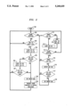
- FIG. 2 illustrates, in flowchart form, the operations of a controller
- Output selector 107 applies the required bias to LED 101 via conductor 111 and 117 and to LED 102 via conductors 112 and 118.
- output selector 107 supplies current to a LED in the light emitting state by means of a reversible voltage source which is current limited by means of a resistor in the path attached to the anode of the LED.
- the current limit resistor can serve as a sensing resistor to determine the reverse bias current.
- Controller 103 can be implemented using either a microprocessor or wired logic.
- FIG. 2 shows a flowchart of the operations performed by controller 103.
- controller 103 Upon being reset, controller 103 starts at block 201.
- Block 202 tests for whether an operational condition has been detected by activation circuit 115 on the printed circuit board. If the answer is no, control is passed to decision block 203 which checks to see whether the time has elapsed for the periodic checking of the LEDs. If it is time to check the LEDs, block 204 is executed which flashes LED 101 and detects whether or not light greater than the predefined level was detected by LED 102.
- Decision block 205 determines whether or not light was detected by LED 102.
- control is passed to 206 which flashes LED 102 and tests to see whether LED 101 detected light greater than the predefined level.
- Decision block 207 determines whether LED 101 detected light greater than the predefined level. If the answer is yes, control is returned to decision block 202. If the answer was no, control is transferred to block 208 which sets an internal error flag within controller 103. In addition, block 209 transmits an error condition signal to central processor 110. Returning to decision block 205. If LED 102 did not detect light from LED 101, control is transferred to block 208. The operation of blocks 208 and 209 has been described.
- Decision block 214 then checks to make sure that the alarm condition still exits; and if the alarm condition no longer exists, control is transferred back to decision block 202. Assuming that the alarm condition still exists, control is passed to decision block 215. Decision block 215 checks to see whether the error flag is set. If the error flag has not been set, then controller 103 verifies that LED 102 is detecting light from LED 101 by execution blocks 216 and 217. If LED 102 is not detecting light, the error flag is set by execution of block 218 and control is returned to decision block 211.
- FIG. 3 illustrates a physical implementation of LEDs 101 and 102.
- the light emitting diodes are physically mounted within a common physical package. Each LED is mounted on a physical post and is wire bonded to an adjacent physical post.
- the LED which is used as a detector operates from the light reflected off the surface of the package by the LED that is under test due to an refractive index mismatch between the lens of the package and the surrounding air and Raleigh scattering.
- FIG. 4 illustrates a physical implementation of the LED pair which utilizes the LED each mounted in its own physical package but the semi-reflector 401 is utilized to return some of the light from the LED under test back to the LED being utilized as a detector.
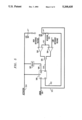
- flip-flop 506 Before reception of an activation signal, flip-flop 506 is in the set state for the following reasons.
- the preset (PS) input of flip-flop 506 is directly connected to conductor 514. Since the activation signal is true at a high voltage ("1") and false at a low voltage (“0"), flip-flop 506 is set via the PS input before the transmission of the activation signal.
- LED 501 When the activation signal is received via conductor 514, LED 501 is forward biased and should emit light.
- LED 502 is directly controlled by the Q output of flip-flop 506 via conductor 512 and the complement of the Q output of flip-flop 506 via conductor 513, LED 502 is in the reversed biased state, when flip-flop 506 is in the set state.
- the voltage across resistor 515 indicates the amount of light being emitted by LED 501, and voltage comparators 503 and 504 continuously verify that the voltage across resistor 515 is within the voltage range as defined by the high and low reference voltages. If the voltage across resistor 515 is within the specified voltage range, both amplifiers transmit a high voltage ("1") to AND gate 505 which in turn transmits a "1" to the D input of flip-flop 506 via conductor 510.
- central processor 110 could control activation circuit to perform periodic testing of the indicator circuit of FIG. 5.
Landscapes
- Engineering & Computer Science (AREA)
- Computer Hardware Design (AREA)
- Microelectronics & Electronic Packaging (AREA)
- General Engineering & Computer Science (AREA)
- Physics & Mathematics (AREA)
- General Physics & Mathematics (AREA)
- Led Devices (AREA)
Abstract
Description
Claims (8)
Priority Applications (1)
| Application Number | Priority Date | Filing Date | Title |
|---|---|---|---|
| US07/922,895 US5268635A (en) | 1992-07-31 | 1992-07-31 | Intelligent self-diagnosing and sparing light emitting diodes |
Applications Claiming Priority (1)
| Application Number | Priority Date | Filing Date | Title |
|---|---|---|---|
| US07/922,895 US5268635A (en) | 1992-07-31 | 1992-07-31 | Intelligent self-diagnosing and sparing light emitting diodes |
Publications (1)
| Publication Number | Publication Date |
|---|---|
| US5268635A true US5268635A (en) | 1993-12-07 |
Family
ID=25447733
Family Applications (1)
| Application Number | Title | Priority Date | Filing Date |
|---|---|---|---|
| US07/922,895 Expired - Lifetime US5268635A (en) | 1992-07-31 | 1992-07-31 | Intelligent self-diagnosing and sparing light emitting diodes |
Country Status (1)
| Country | Link |
|---|---|
| US (1) | US5268635A (en) |
Cited By (24)
| Publication number | Priority date | Publication date | Assignee | Title |
|---|---|---|---|---|
| US5570035A (en) * | 1995-01-31 | 1996-10-29 | The United States Of America As Represented By The Secretary Of The Army | Built-in self test indicator for an integrated circuit package |
| US5617036A (en) * | 1995-02-24 | 1997-04-01 | The Whitaker Corporation | Laser/pin assembly with integrated burn-in assembly |
| US5627379A (en) * | 1994-12-23 | 1997-05-06 | Lucent Technologies Inc. | Duplication detection of circuit board removal using two light emitting diodes |
| US5692084A (en) * | 1996-06-11 | 1997-11-25 | The Whitaker Corporation | Package for an optoelectronic device |
| US5764836A (en) * | 1996-06-11 | 1998-06-09 | The Whitaker Corporation | Pigtailed package for an optoelectronic device |
| US6028441A (en) * | 1997-08-14 | 2000-02-22 | Alvord; Robert J. | Self-test routine and circuit for LED display |
| US6392553B1 (en) * | 2000-08-22 | 2002-05-21 | Harmon Industries, Inc. | Signal interface module |
| US20030122749A1 (en) * | 2001-12-31 | 2003-07-03 | Booth Lawrence A. | Energy sensing light emitting diode display |
| US20040071471A1 (en) * | 2002-10-10 | 2004-04-15 | Interlink Electronics, Inc. | Method and system for pairing a remote control transmitter and receiver |
| US20040208632A1 (en) * | 2002-04-03 | 2004-10-21 | Mitsubishi Electric Research Laboratories, Inc. | Communication using bi-directional LEDs |
| US20040247484A1 (en) * | 2002-09-20 | 2004-12-09 | Yerazunis William S. | Multi-way LED-based surface reflectance sensor and spectrophotometer |
| US20060028156A1 (en) * | 2004-08-06 | 2006-02-09 | Paul Jungwirth | Lighting system including photonic emission and detection using light-emitting elements |
| US20060031729A1 (en) * | 2004-08-09 | 2006-02-09 | Maytag Corporation | Apparatus with self-test circuit |
| US7130340B1 (en) * | 2000-10-27 | 2006-10-31 | Sun Microsystems, Inc. | Noise margin self-diagnostic receiver logic |
| DE202008002020U1 (en) * | 2008-02-13 | 2009-03-05 | Steca Elektronik Gmbh | Electronic switch |
| US20130163922A1 (en) * | 2011-12-21 | 2013-06-27 | Youngtek Electronics Corporation | Light-guiding cover structure |
| US8598778B2 (en) | 2007-07-19 | 2013-12-03 | Quarkstar Llc | Light emitting device having a specific dimension of phosphor layer |
| US9291763B2 (en) | 2012-09-13 | 2016-03-22 | Quarkstar Llc | Light-emitting device with remote scattering element and total internal reflection extractor element |
| US9683710B2 (en) | 2013-03-07 | 2017-06-20 | Quarkstar Llc | Illumination device with multi-color light-emitting elements |
| US9752757B2 (en) | 2013-03-07 | 2017-09-05 | Quarkstar Llc | Light-emitting device with light guide for two way illumination |
| US9863605B2 (en) | 2011-11-23 | 2018-01-09 | Quarkstar Llc | Light-emitting devices providing asymmetrical propagation of light |
| US9915410B2 (en) | 2012-09-13 | 2018-03-13 | Quarkstar Llc | Light-emitting devices with reflective elements |
| US10811576B2 (en) | 2013-03-15 | 2020-10-20 | Quarkstar Llc | Color tuning of light-emitting devices |
| US10994035B2 (en) | 2015-12-22 | 2021-05-04 | 3M Innovative Properties Company | Disinfecting system with performance monitoring |
Citations (2)
| Publication number | Priority date | Publication date | Assignee | Title |
|---|---|---|---|---|
| JPS5414079A (en) * | 1977-07-04 | 1979-02-01 | Komatsu Ltd | Trouble detector for light-ray type safety device |
| JPS59126967A (en) * | 1983-01-10 | 1984-07-21 | Toshiba Corp | Testing device of led matrix display |
-
1992
- 1992-07-31 US US07/922,895 patent/US5268635A/en not_active Expired - Lifetime
Patent Citations (2)
| Publication number | Priority date | Publication date | Assignee | Title |
|---|---|---|---|---|
| JPS5414079A (en) * | 1977-07-04 | 1979-02-01 | Komatsu Ltd | Trouble detector for light-ray type safety device |
| JPS59126967A (en) * | 1983-01-10 | 1984-07-21 | Toshiba Corp | Testing device of led matrix display |
Cited By (54)
| Publication number | Priority date | Publication date | Assignee | Title |
|---|---|---|---|---|
| US5627379A (en) * | 1994-12-23 | 1997-05-06 | Lucent Technologies Inc. | Duplication detection of circuit board removal using two light emitting diodes |
| US5570035A (en) * | 1995-01-31 | 1996-10-29 | The United States Of America As Represented By The Secretary Of The Army | Built-in self test indicator for an integrated circuit package |
| US5617036A (en) * | 1995-02-24 | 1997-04-01 | The Whitaker Corporation | Laser/pin assembly with integrated burn-in assembly |
| US5937124A (en) * | 1996-02-29 | 1999-08-10 | The Whitaker Corporation | Package for an optoelectronic device |
| US5692084A (en) * | 1996-06-11 | 1997-11-25 | The Whitaker Corporation | Package for an optoelectronic device |
| US5764836A (en) * | 1996-06-11 | 1998-06-09 | The Whitaker Corporation | Pigtailed package for an optoelectronic device |
| US6028441A (en) * | 1997-08-14 | 2000-02-22 | Alvord; Robert J. | Self-test routine and circuit for LED display |
| US6087846A (en) * | 1997-08-14 | 2000-07-11 | Ranco Incorporated Of Delware | Self-test routine for LED display |
| US6392553B1 (en) * | 2000-08-22 | 2002-05-21 | Harmon Industries, Inc. | Signal interface module |
| US7130340B1 (en) * | 2000-10-27 | 2006-10-31 | Sun Microsystems, Inc. | Noise margin self-diagnostic receiver logic |
| US8963817B2 (en) | 2001-12-31 | 2015-02-24 | Intel Corporation | Energy sensing light emitting diode display |
| US9665211B2 (en) | 2001-12-31 | 2017-05-30 | Intel Corporation | Energy sensing light emitting diode display |
| US7348946B2 (en) | 2001-12-31 | 2008-03-25 | Intel Corporation | Energy sensing light emitting diode display |
| US8026879B2 (en) | 2001-12-31 | 2011-09-27 | Intel Corporation | Energy sensing light emitting diode display |
| US20030122749A1 (en) * | 2001-12-31 | 2003-07-03 | Booth Lawrence A. | Energy sensing light emitting diode display |
| US20080174530A1 (en) * | 2001-12-31 | 2008-07-24 | Booth Lawrence A | Energy sensing light emitting diode display |
| US20040208632A1 (en) * | 2002-04-03 | 2004-10-21 | Mitsubishi Electric Research Laboratories, Inc. | Communication using bi-directional LEDs |
| US7072587B2 (en) * | 2002-04-03 | 2006-07-04 | Mitsubishi Electric Research Laboratories, Inc. | Communication using bi-directional LEDs |
| US20040247484A1 (en) * | 2002-09-20 | 2004-12-09 | Yerazunis William S. | Multi-way LED-based surface reflectance sensor and spectrophotometer |
| US7170606B2 (en) * | 2002-09-20 | 2007-01-30 | Mitsubishi Electric Research Laboratories, Inc. | Multi-way LED-based surface reflectance sensor and spectrophotometer |
| WO2004034610A1 (en) * | 2002-10-10 | 2004-04-22 | Interlink Electronics, Inc. | Method and system for pairing a remote control transmitter and receiver |
| US20040071471A1 (en) * | 2002-10-10 | 2004-04-15 | Interlink Electronics, Inc. | Method and system for pairing a remote control transmitter and receiver |
| EP1779708A4 (en) * | 2004-08-06 | 2010-08-18 | Koninkl Philips Electronics Nv | Lighting system including photonic emission and detection using light-emitting elements |
| EP1779708A1 (en) * | 2004-08-06 | 2007-05-02 | Tir Systems Ltd. | Lighting system including photonic emission and detection using light-emitting elements |
| WO2006012737A1 (en) * | 2004-08-06 | 2006-02-09 | Tir Systems Ltd. | Lighting system including photonic emission and detection using light-emitting elements |
| US7329998B2 (en) | 2004-08-06 | 2008-02-12 | Tir Systems Ltd. | Lighting system including photonic emission and detection using light-emitting elements |
| US20060028156A1 (en) * | 2004-08-06 | 2006-02-09 | Paul Jungwirth | Lighting system including photonic emission and detection using light-emitting elements |
| US7111218B2 (en) * | 2004-08-09 | 2006-09-19 | Maytag Corporation | Apparatus with self-test circuit |
| US20060031729A1 (en) * | 2004-08-09 | 2006-02-09 | Maytag Corporation | Apparatus with self-test circuit |
| US9420664B2 (en) | 2007-07-19 | 2016-08-16 | Quarkstar Llc | Light emitting device including nearly index-matched luminescent glass-phosphor composites |
| US10746374B2 (en) | 2007-07-19 | 2020-08-18 | Quarkstar Llc | Nearly index-matched luminescent glass-phosphor composites for photonic applications |
| US8598778B2 (en) | 2007-07-19 | 2013-12-03 | Quarkstar Llc | Light emitting device having a specific dimension of phosphor layer |
| US8791631B2 (en) | 2007-07-19 | 2014-07-29 | Quarkstar Llc | Light emitting device |
| US9078332B2 (en) | 2007-07-19 | 2015-07-07 | Quarkstar Llc | Light emitting device having a specific dimension of phosphor layer |
| DE202008002020U1 (en) * | 2008-02-13 | 2009-03-05 | Steca Elektronik Gmbh | Electronic switch |
| US10408428B2 (en) | 2011-11-23 | 2019-09-10 | Quarkstar Llc | Light-emitting devices providing asymmetrical propagation of light |
| US11353167B2 (en) | 2011-11-23 | 2022-06-07 | Quarkstar Llc | Light-emitting devices providing asymmetrical propagation of light |
| US11009193B2 (en) | 2011-11-23 | 2021-05-18 | Quarkstar Llc | Light-emitting devices providing asymmetrical propagation of light |
| US9863605B2 (en) | 2011-11-23 | 2018-01-09 | Quarkstar Llc | Light-emitting devices providing asymmetrical propagation of light |
| US10451250B2 (en) | 2011-11-23 | 2019-10-22 | Quickstar LLC | Light-emitting devices providing asymmetrical propagation of light |
| US8873920B2 (en) * | 2011-12-21 | 2014-10-28 | Youngtek Electronics Corporation | Light-guiding cover structure |
| US20130163922A1 (en) * | 2011-12-21 | 2013-06-27 | Youngtek Electronics Corporation | Light-guiding cover structure |
| US9915410B2 (en) | 2012-09-13 | 2018-03-13 | Quarkstar Llc | Light-emitting devices with reflective elements |
| US10274167B2 (en) | 2012-09-13 | 2019-04-30 | Quarkstar Llc | Light-emitting devices with reflective elements |
| US10088618B2 (en) | 2012-09-13 | 2018-10-02 | Quarkstar Llc | Light-emitting device with remote scattering element and total internal reflection extractor element |
| US9291763B2 (en) | 2012-09-13 | 2016-03-22 | Quarkstar Llc | Light-emitting device with remote scattering element and total internal reflection extractor element |
| US10907797B2 (en) | 2012-09-13 | 2021-02-02 | Quarkstar Llc | Light-emitting devices with reflective elements |
| US10222008B2 (en) | 2013-03-07 | 2019-03-05 | Quarkstar Llc | Illumination device with multi-color light-emitting elements |
| US10429034B2 (en) | 2013-03-07 | 2019-10-01 | Quarkstar Llc | Light-emitting device with light guide for two way illumination |
| US10774999B2 (en) | 2013-03-07 | 2020-09-15 | Quarkstar Llc | Illumination device with multi-color light-emitting elements |
| US9752757B2 (en) | 2013-03-07 | 2017-09-05 | Quarkstar Llc | Light-emitting device with light guide for two way illumination |
| US9683710B2 (en) | 2013-03-07 | 2017-06-20 | Quarkstar Llc | Illumination device with multi-color light-emitting elements |
| US10811576B2 (en) | 2013-03-15 | 2020-10-20 | Quarkstar Llc | Color tuning of light-emitting devices |
| US10994035B2 (en) | 2015-12-22 | 2021-05-04 | 3M Innovative Properties Company | Disinfecting system with performance monitoring |
Similar Documents
| Publication | Publication Date | Title |
|---|---|---|
| US5268635A (en) | Intelligent self-diagnosing and sparing light emitting diodes | |
| US4870269A (en) | Optical-fiber detection device which involves testing for good performance | |
| US5345230A (en) | Method and apparatus for optical transceiver testing | |
| US7372369B2 (en) | Monitoring of alarm system wiring | |
| US8299911B2 (en) | Testing device for hazard alarm systems | |
| US7652480B2 (en) | Methods and systems for testing a functional status of a light unit | |
| US7382245B2 (en) | Method and apparatus for indicating a power condition at a notification appliance | |
| US5387899A (en) | Alarm system with monitoring circuit for detecting a cut or short in a pair of wires | |
| EP0241270A1 (en) | Self-testing monitoring circuit | |
| EP0626743B1 (en) | Line fault monitoring apparatus | |
| US4091292A (en) | Fail-safe monitor of d.c. voltage | |
| US3999126A (en) | Test device for simultaneously displaying the level of logic signals in a plurality of circuits | |
| US4849734A (en) | Self-diagnostic circuit for alarm-systems | |
| US5331319A (en) | Device for signalling the position of a mobile member | |
| US6917164B2 (en) | Light signaling device related to the operating state of a system | |
| US20090322549A1 (en) | Method and Apparatus for Zone Selection in Area Monitoring Devices | |
| JPS62501534A (en) | Portable test equipment for monitoring data communication systems | |
| CA2406582C (en) | Process for management of a light signaling device, and a device using this process, particularly for avionics | |
| JPS59142476A (en) | Cable checker | |
| JP2573651B2 (en) | Signal processing device | |
| JP2802760B2 (en) | Connector disconnection detection circuit | |
| JPH04477Y2 (en) | ||
| GB2159988A (en) | Safety device | |
| KR101146083B1 (en) | Invasion detection apparatus and method for having self-diagnosis function | |
| KR960013963B1 (en) | Self examination device for telecommunication system |
Legal Events
| Date | Code | Title | Description |
|---|---|---|---|
| AS | Assignment |
Owner name: AMERICAN TELEPHONE AND TELEGRAPH COMPANY A NY COR Free format text: ASSIGNMENT OF ASSIGNORS INTEREST.;ASSIGNORS:BORTOLINI, JAMES R.;GRIMES, GARY J.;REEL/FRAME:006200/0959;SIGNING DATES FROM 19920730 TO 19920731 |
|
| STCF | Information on status: patent grant |
Free format text: PATENTED CASE |
|
| FEPP | Fee payment procedure |
Free format text: PAYOR NUMBER ASSIGNED (ORIGINAL EVENT CODE: ASPN); ENTITY STATUS OF PATENT OWNER: LARGE ENTITY |
|
| FPAY | Fee payment |
Year of fee payment: 4 |
|
| FEPP | Fee payment procedure |
Free format text: PAYER NUMBER DE-ASSIGNED (ORIGINAL EVENT CODE: RMPN); ENTITY STATUS OF PATENT OWNER: LARGE ENTITY Free format text: PAYOR NUMBER ASSIGNED (ORIGINAL EVENT CODE: ASPN); ENTITY STATUS OF PATENT OWNER: LARGE ENTITY |
|
| FPAY | Fee payment |
Year of fee payment: 8 |
|
| FPAY | Fee payment |
Year of fee payment: 12 |
|
| AS | Assignment |
Owner name: LUCENT TECHNOLOGIES INC., NEW JERSEY Free format text: ASSIGNMENT OF ASSIGNORS INTEREST;ASSIGNOR:AT&T CORP.;REEL/FRAME:023649/0645 Effective date: 19960329 |
|
| AS | Assignment |
Owner name: AGERE SYSTEMS OPTOELECTRONICS GUARDIAN CORP., PENN Free format text: ASSIGNMENT OF ASSIGNORS INTEREST;ASSIGNOR:LUCENT TECHNOLOGIES;REEL/FRAME:023660/0354 Effective date: 20010131 Owner name: AGERE SYSTEMS INC., PENNSYLVANIA Free format text: MERGER;ASSIGNOR:AGERE SYSTEMS GUARDIAN CORP.;REEL/FRAME:023660/0393 Effective date: 20020831 Owner name: AGERE SYSTEMS GUARDIAN CORP., PENNSYLVANIA Free format text: MERGER;ASSIGNOR:AGERE SYSTEMS OPTOELECTRONICS GUARDIAN CORP.;REEL/FRAME:023660/0386 Effective date: 20010831 |