US5264126A - Clarifier drive for waste water treatment system - Google Patents
Clarifier drive for waste water treatment system Download PDFInfo
- Publication number
- US5264126A US5264126A US07/944,773 US94477392A US5264126A US 5264126 A US5264126 A US 5264126A US 94477392 A US94477392 A US 94477392A US 5264126 A US5264126 A US 5264126A
- Authority
- US
- United States
- Prior art keywords
- drive
- support
- torque transfer
- transfer ring
- drive cage
- Prior art date
- Legal status (The legal status is an assumption and is not a legal conclusion. Google has not performed a legal analysis and makes no representation as to the accuracy of the status listed.)
- Expired - Lifetime
Links
Images


Classifications
-
- B—PERFORMING OPERATIONS; TRANSPORTING
- B01—PHYSICAL OR CHEMICAL PROCESSES OR APPARATUS IN GENERAL
- B01D—SEPARATION
- B01D21/00—Separation of suspended solid particles from liquids by sedimentation
- B01D21/18—Construction of the scrapers or the driving mechanisms for settling tanks
- B01D21/20—Driving mechanisms
-
- Y—GENERAL TAGGING OF NEW TECHNOLOGICAL DEVELOPMENTS; GENERAL TAGGING OF CROSS-SECTIONAL TECHNOLOGIES SPANNING OVER SEVERAL SECTIONS OF THE IPC; TECHNICAL SUBJECTS COVERED BY FORMER USPC CROSS-REFERENCE ART COLLECTIONS [XRACs] AND DIGESTS
- Y10—TECHNICAL SUBJECTS COVERED BY FORMER USPC
- Y10T—TECHNICAL SUBJECTS COVERED BY FORMER US CLASSIFICATION
- Y10T74/00—Machine element or mechanism
- Y10T74/21—Elements
- Y10T74/2186—Gear casings
Definitions
- This invention relates to water and wastewater treatment.
- it relates to an improvement in a mechanism that drives flight arms in a clarifier.
- Center driven circular collectors or clarifiers are almost universally used in the United States as a settling or clarifying step in the treatment of water and wastewater. They provide an opportunity for solids that are suspended in the fluid being treated to fall to the bottom of the clarifier where they can be removed as sludge. The clear liquid is then skimmed off of the top of the clarifier and directed to additional treatment processes.
- a set of angled metal squeegees are provided for this purpose.
- the squeegees are arranged to "plow" the sludge to a receptacle where it is removed from the clarifier by any of a number of methods known to those of skill in the art.
- the squeegees are coupled to clarifier arms or flight arms that extend across the radius of the clarifier and that are supported by and adapted to rotate about a vertical pier positioned at the center of the clarifier. By rotating the flight arms within the circular clarifier, the squeegees are able to efficiently sweep substantially the entire floor of the clarifier.
- the flight arms and their associated squeegees are driven by a mechanism located on the pier in the center of the clarifier.
- the flight arms are connected to the lower end of a drive cage that encircles the central pier.
- the top of the drive cage is coupled to a drive cage support located near the top of the pier.
- the drive cage support is coupled to a hoop or ring gear that is internally cut and supported by a suitable bearing assembly, and the gear is driven by a pinion that is in turn driven by any suitable power source, typically an electric motor coupled to the pinion via one or more gear reducer assemblies.
- the squeegees, flight arms, drive cage and drive cage support together may be referred to as the driven assembly.
- a driven assembly may just consist of squeegees, flight arms, and a drive cage.
- the drive cage support is generally a steel casting, however it may be made from welded steel.
- the driven assembly and its components may, thus, comprise numerous components rigidly connected. Independent of the terminology used, the driven assembly is typically coupled to a gear or other driven mechanism such that the clarifier floor is substantially swept.
- the clarifier thus typically includes stationary parts, which do not rotate with respect to the pier, including a drive housing, an outer bearing race, a cover plate to cover and protect the gear and bearing assembly and to support the power source, and the power source itself.
- the clarifier also includes rotating parts, including the hoop gear with its integral inner bearing race, the rotating drive cage support and the driven assembly.
- a clarifier is often equipped with an access bridge, which typically includes a walkway from the edge of the clarifier to the center where the pier is located, and perhaps a working platform constructed above the pier.
- the bridge provides convenient access for inspection and maintenance of the various clarifier drive components.
- the drive mechanism typically requires the most maintenance.
- the weight of the flight arms is borne by the bearings positioned between the inner and outer races, and the torque required to drive the flight arms is transmitted through the pinion and hoop gear to the other rotating components. It is therefore occasionally necessary to gain access . to the hoop gear, ball bearings and bearing races for maintenance or replacement.
- the present invention eliminates the need to disconnect and support the drive cage and flight arms prior to disassembling the drive assembly.
- a novel torque transfer ring design is employed which allows the drive cage support, drive cage and flight arms to be temporarily supported by the stationary drive housing while the torque transfer ring, hoop gear, bearing races and bearings are removed for maintenance or replacement.
- the entire mechanism can be disassembled and reassembled quickly and easily from the bridge with the aid of, for example, a portable engine hoist, eliminating many hours or even days of down-time for disconnecting and supporting the drive cage, flight arms and squeegees, and likely drainage of the clarifier basin. Also, the expense of engaging a motor crane is avoided.
- a torque transfer ring is adapted to be connected between the hoop gear and the rotating drive cage support.
- the torque transfer ring has a plurality of outer bolt holes to correspond with bolt holes in the drive cage support and a plurality of inner bolt holes to correspond with bolt holes in the hoop gear.
- Means are provided for supporting the drive cage support and the driven assembly, which includes the drive cage, flight arms, flights, and squeegees, such that the drive cage support may be disconnected from the torque transfer ring without requiring additional support for the drive cage support and the driven assembly and without disconnecting the drive cage from the drive cage support.
- the drive cage support may be supported by a plurality of support screws adapted to pass through the outer bolt holes in the torque transfer ring and to engage threaded bolt holes in the drive cage support so as to protrude beneath the drive cage support to contact the stationary drive housing, and to thereby support the drive cage support and the driven assembly upon the drive housing.
- the invention also includes means for supporting the bridge above the pier and adapted to provide clearance to permit removal of the torque ring, hoop gear, bearings and raceways.
- this means comprises a plurality of jack bolts which engage bridge members and which are adapted to rest on top of the drive cage support, which is in turn supported by the drive housing while the torque transfer ring is removed.
- the bridge ordinarily covers and is supported by the cover plate of the drive housing.
- the bridge is designed to be partially disassemblable to provide access for removal of the cover plate and the underlying components.
- the bridge comprises removable platform support channels adapted to be secured to the cover plate of the drive means, which platform support channels may be removed when the bridge is supported by the above-mentioned jack bolts. Removal of the platform support channels permits removal of the cover plate for access to the pinion gear, torque ring, hoop gear, bearings, and bearing races and other components of the drive mechanism.
- the present invention therefore provides an improved device which allows maintenance to be performed on a clarifier drive mechanism without draining the clarifier and without disconnecting the driven assembly from the pier or disassembling the driven assembly, in particular without requiring lifting, shoring up or supporting the driven assembly and without requiring unbolting the driven assembly from the drive cage support.
- the driven assembly continuously rests on the pier during drive mechanism maintenance.
- the present invention may have applications in wastewater basin driven assemblies other than clarifiers, such as in thickeners.
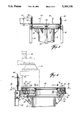
- FIG. 1 is a cross-sectional view of a center driven water clarifier.
- FIG. 2 is a plan view of a water clarifier platform according to this invention.
- FIG. 3 is a side elevation view of the platform of FIG. 2 illustrating the removable platform support channels.
- FIG. 4 is cross-sectional view, along section line 4 of FIG. 2, of the clarifier drive mechanism according to this invention.
- FIG. 5 is a plan view of the clarifier drive mechanism according to this invention, illustrating the torque transfer ring when the cover plate is removed.
- FIG. 5A is a cross-sectional detail illustration showing the torque transfer ring, hoop gear, drive cage support and drive housing according to the present invention, illustrating the drive housing directly supporting the drive cage support.
- FIG. 6 is an exploded cross-sectional view, along section line 6 of FIG. 5, illustrating the removal of the torque transfer ring and the hoop gear.
- FIG. 1 A typical center driven water clarifier 10 is shown in FIG. 1.
- Wastewater enters clarifier 12, generally a circular basin, through influent pipe 14, center pier 16, and influent ports 18.
- Sludge is removed from clarifier floor 26 through sludge return pipe 24.
- Center pier 16 supports the mechanisms which support and rotate flight arms 22, including motor 28, drive cage support 30 coupled to motor 28, and drive cage 32.
- Drive cage 32 is generally coupled to drive cage support 30 near the upper portion of center pier 16 (see FIG. 3).
- Platform 36 and connected bridge 25 may also be supported by center pier 16. This invention may also be used in other types of clarifier configurations.
- FIG. 2 A top view above center pier 16 of a water clarifier using an embodiment of the present invention is shown in FIG. 2.
- Platform 36 consists of platform support channels 40 and disassembly support channels 42.
- platform support channels 40 supported by cover plate 44, are secured to cover plate 44 by platform support fasteners 46.
- Cover plate 44 supported by center pier 16, is a nonrotating plate covering a portion of the drive mechanism.
- the drive mechanism comprises a drive housing, gears, a torque transfer ring, and bearings that transfer power from motor 28 to drive cage 32.
- FIG. 2 also shows the top of drive cage 32 and rotating drive cage support 30.
- drive cage support 30 has four drive cage support extensions 34 spaced 90 degrees apart around the periphery of the drive cage support.
- drive cage support 30 is rotated such that extensions 34 are positioned under disassembly support channels 42 as shown in FIG. 2.
- Jackbolts 48 are then used to support disassembly support channels 42 on drive cage support 30.
- platform support channels 40 may be removed after fasteners 46 and fasteners 50 are unfastened.
- Platform support channels 40 provides clearance to permit a workman to lift and remove cover plate 44 and to then maintain, replace or disassemble the mechanisms located under cover plate 44.
- Equally effective embodiments of the present invention may be constructed which use substantially different platform or bridge arrangements. Also, alternative means may be provided for gaining access to the internal mechanisms below plate 44.
- FIG. 3 A side view of a preferred embodiment showing the accessibility of cover plate 44 is provided in FIG. 3.
- Platform support channels 40 that have been unfastened and removed are shown by dashed lines.
- Disassembly support channels 42 are now supported, through jackbolts 48 and jackbolt nuts 49, by drive cage support extensions 34.
- FIG. 3 also displays a connection between drive cage 32 and drive cage support 30 at drive cage support extensions 34.
- Drive cage 32 and drive cage support 30 may even be formed in one piece.
- means other than the drive cage support extensions 34 as illustrated may be used to place the drive cage support under the disassembly support channels. For example, the entire drive cage support may extend far enough radially to extend under the disassembly support channels.
- FIG. 4 shows a cross section of the invention with cover plate 44 in place, but with platform support members 40 removed.
- Motor 28 and reducer assembly 50 shown as dashed lines, are understood to be removed prior to gear disassembly and both are standard mechanisms well known in the art.
- Reducer assembly 50 typically comprises both primary and intermediate reducers.
- Drive pinion 58 is coupled to reducer assembly 50 in order to provide torque to the gears.
- cover plate 44 is connected to drive housing 52 with bolts 54 bolts or other suitable fastening means.
- Drive housing 52 is made of a rigid material, such as steel or cast iron.
- Drive housing 52 is in turn connected to center pier 16 with bolts 56 or other suitable means.
- drive pinion 58 operatively engages hoop gear 62.
- Hoop gear assembly 60 comprises (a) hoop gear 62 which has an integral inner bearing race, (b) an outer stationary bearing race 64 and (c) bearings 66.
- Outer stationary bearing race 64 is secured to drive housing 52 by bolts 76 or other fastening means.
- a suitable hoop gear assembly which includes the inner race, the outer race, and the ball bearings is available as a unit from, for example, Avon Bearings Corporation, Avon Ohio, as a Series T-bearing/internal gear.
- a spur gear is used.
- a helical, herring bone, or other type of gear may also be suitable for use in this invention.
- cast iron bearing races with strip liners may be utilized with the present invention as well as the preferred steel bearing assemblies.
- Torque transfer ring 70 is connected to hoop gear 62 of hoop gear assembly 60 by torque transfer ring inner bolts 72, such as 3/4" hex-head machine bolts or other suitable fastening means.
- torque transfer ring 70 transfers torque from hoop gear 62 to drive cage support 30 by connecting torque transfer ring 70 to drive cage support 30 using torque transfer ring outer bolts 74, such as 3/4" hex-head machine bolts or other suitable fastening means.
- torque transfer ring outer bolts 74 such as 3/4" hex-head machine bolts or other suitable fastening means.
- FIG. 5 A top view of a preferred embodiment of the invention is displayed in FIG. 5 with motor 28, reducer 50 and cover plate 44 removed. As can be more clearly seen in FIG. 5, drive pinion 58 operatively engages hoop gear 62. Also, torque transfer ring 70 has a ring of torque transfer ring outer bolts 74 and a ring of torque transfer ring inner bolts 72.
- torque transfer ring After cover plate 44 is removed during disassembly to repair or replace gear assembly 60, the torque transfer ring must be disengaged from hoop gear 62 of hoop gear assembly 60 and from drive cage support 30. Thus, torque transfer ring outer bolts 74 and inner bolts 72 must be removed. However, since torque transfer ring outer bolts 74 support drive cage support 30, which in turn supports drive cage 32 and flight arms 22, alternative means is needed to support drive cage support 30.
- such supporting means may be provided by inserting a shoulderless socket support screw 80 or other suitable screw into the vacated bolt hole created by removing torque transfer ring outer bolt 74. Since support screw 80 is shoulderless, it may be screwed below torque transfer ring 70 through threads in drive cage support 30 and into supporting contact with drive housing 52. With support screw 80 installed, drive cage support 30 is supported by drive housing 52 through screw 80. Preferably, at least eight support screws 80 should be placed in the series of vacated torque transfer ring outer bolt holes. The preferred steps for disassembly of the drive mechanism will be described in more detail below.
- torque transfer ring 70 may be lifted out of drive housing 52 and bolts 76 which secure outer stationary bearing race 64 of hoop gear assembly 60 to drive housing 52 may be removed. Hoop gear assembly 60 may then be removed from drive housing 52 for maintenance or replacement.
- FIG. 6 shows torque transfer ring 70 and hoop gear assembly 60 lifted out of drive housing 52.
- removal of hoop gear assembly 60 is possible while drive cage support 30 and drive cage 32 are supported by center pier 16 through drive housing 52 and support screws 80. Therefore, clarifier 12 does not have to be drained and support does not have to be provided for the flight arms 22 and the drive cage 32 while hoop gear assembly 60 is serviced.
- Torque transfer ring 70 may be formed as a single unitary piece, or it may comprise a plurality of ring segments which connect hoop gear 62 to drive cage support 30.
- drive cage support 30 is rotated such that drive cage support extensions 34 are positioned under disassembly support channels 42.
- Platform support fasteners 46 that secure platform 36 and bridge 35 to cover plate 44 are then removed.
- jackbolts 48 are inserted through disassembly support channels 42 and jackbolt nuts 49 are positioned so that platform 36 and bridge 35 are supported by jackbolts 48 which preferably engaged all four drive cage support extensions 34.
- Fasteners 50 are then unfastened, allowing platform support channels 40 to be removed.
- Motor 28 and reducer assembly 50 are hoisted and detached from the clarifier. It would be apparent to one of skill in the art that the sequence of these steps could be altered.
- torque transfer ring outer bolts 74 may be removed.
- the bolts removed are evenly spaced around the outer bolt circle. It is understood that the number of bolts in the bolt circle, and the number of bolts removed, may be varied depending on the specific application of the invention.
- a shoulderless socket support screw 80 is inserted and screwed through threads in the bolt hole of drive cage support 30 until firm contact with drive housing 52 is made.
- more torque transfer ring outer bolts 74 are removed, and some or all of them may similarly be replaced with shoulderless socket support screws 80.
- four additional support screws 80 may be inserted, such that the drive cage support 30 is supported by eight support screws 80.
- any remaining torque transfer ring outer bolts 74 are removed.
- drive cage support 30 is supported directly on drive housing 52 by virtue of at least four shoulderless socket support screws 80.
- the remaining torque transfer ring outer bolts 74 and all of the torque transfer ring inner bolts 72 may then be removed.
- Torque transfer ring 70 may then be removed from drive housing 52, exposing gear assembly 60 to permit its removal or maintenance.
Landscapes
- Chemical & Material Sciences (AREA)
- Chemical Kinetics & Catalysis (AREA)
- Gear Transmission (AREA)
Abstract
Description
Claims (11)
Priority Applications (1)
| Application Number | Priority Date | Filing Date | Title |
|---|---|---|---|
| US07/944,773 US5264126A (en) | 1992-09-14 | 1992-09-14 | Clarifier drive for waste water treatment system |
Applications Claiming Priority (1)
| Application Number | Priority Date | Filing Date | Title |
|---|---|---|---|
| US07/944,773 US5264126A (en) | 1992-09-14 | 1992-09-14 | Clarifier drive for waste water treatment system |
Publications (1)
| Publication Number | Publication Date |
|---|---|
| US5264126A true US5264126A (en) | 1993-11-23 |
Family
ID=25482050
Family Applications (1)
| Application Number | Title | Priority Date | Filing Date |
|---|---|---|---|
| US07/944,773 Expired - Lifetime US5264126A (en) | 1992-09-14 | 1992-09-14 | Clarifier drive for waste water treatment system |
Country Status (1)
| Country | Link |
|---|---|
| US (1) | US5264126A (en) |
Cited By (8)
| Publication number | Priority date | Publication date | Assignee | Title |
|---|---|---|---|---|
| US5481789A (en) * | 1994-02-28 | 1996-01-09 | Envirex, Inc. | Method for removing a gear or bearing in circular clarifiers and thickeners |
| US5534163A (en) * | 1995-06-23 | 1996-07-09 | Westvaco Corporation | Center column extension for a clarifier |
| US5961828A (en) * | 1997-10-02 | 1999-10-05 | Henry Filters, Inc. | Compact drive system utilizing gear box with worm and cycloidal gears |
| GB2361268A (en) * | 2000-04-12 | 2001-10-17 | Anthony George Rawlings | Centre bearing access assembly |
| US6467968B1 (en) | 2001-04-23 | 2002-10-22 | Richard Nils Young | Bearing assembly in circular clarifiers and thickeners and method for replacing same |
| GB2388796A (en) * | 2002-05-24 | 2003-11-26 | Stephen W Taylor | Scum removing apparatus |
| US20150224425A1 (en) * | 2012-10-30 | 2015-08-13 | Flsmidth A/S | Thickener/clarifier drive apparatus and methods thereof |
| US10793351B2 (en) | 2018-12-21 | 2020-10-06 | Curbtender, Inc. | Leaf collection vehicle |
Citations (6)
| Publication number | Priority date | Publication date | Assignee | Title |
|---|---|---|---|---|
| US2855101A (en) * | 1957-02-05 | 1958-10-07 | Dorr Oliver Inc | Overload responsive alarm for drive motor |
| US2866352A (en) * | 1956-01-27 | 1958-12-30 | Dorr Oliver Inc | Drive mechanism for pier supported rotary rake structure for settling tanks |
| US3959151A (en) * | 1974-05-28 | 1976-05-25 | Dorr-Oliver Incorporated | Continuously operating sedimentation tank with pier supported rake structure |
| US4048076A (en) * | 1975-12-29 | 1977-09-13 | Environmental Elements Corporation | Center column drive arrangement for circular clarifiers |
| US5018407A (en) * | 1989-10-27 | 1991-05-28 | Scientific-Atlanta, Inc. | Pedestal assembly having a reduced volume in a lubricant filled housing |
| US5194155A (en) * | 1990-06-20 | 1993-03-16 | Mcnish Corporation | Concentric dual drive system for a flocculating clarifier |
-
1992
- 1992-09-14 US US07/944,773 patent/US5264126A/en not_active Expired - Lifetime
Patent Citations (6)
| Publication number | Priority date | Publication date | Assignee | Title |
|---|---|---|---|---|
| US2866352A (en) * | 1956-01-27 | 1958-12-30 | Dorr Oliver Inc | Drive mechanism for pier supported rotary rake structure for settling tanks |
| US2855101A (en) * | 1957-02-05 | 1958-10-07 | Dorr Oliver Inc | Overload responsive alarm for drive motor |
| US3959151A (en) * | 1974-05-28 | 1976-05-25 | Dorr-Oliver Incorporated | Continuously operating sedimentation tank with pier supported rake structure |
| US4048076A (en) * | 1975-12-29 | 1977-09-13 | Environmental Elements Corporation | Center column drive arrangement for circular clarifiers |
| US5018407A (en) * | 1989-10-27 | 1991-05-28 | Scientific-Atlanta, Inc. | Pedestal assembly having a reduced volume in a lubricant filled housing |
| US5194155A (en) * | 1990-06-20 | 1993-03-16 | Mcnish Corporation | Concentric dual drive system for a flocculating clarifier |
Non-Patent Citations (7)
| Title |
|---|
| Avon Bearings Corporation Design Guide & Catalog, pp. 1 37, 1989. * |
| Avon Bearings Corporation Design Guide & Catalog, pp. 1-37, 1989. |
| Brochure, "Integral gear, precision bearing drives," WesTech Engineering, Inc., 1990. |
| Brochure, "Thickener Drives," Walker Process Equipment, Inc. |
| Brochure, Eimco Process Equipment Company. * |
| Brochure, Integral gear, precision bearing drives, WesTech Engineering, Inc., 1990. * |
| Brochure, Thickener Drives, Walker Process Equipment, Inc. * |
Cited By (11)
| Publication number | Priority date | Publication date | Assignee | Title |
|---|---|---|---|---|
| US5481789A (en) * | 1994-02-28 | 1996-01-09 | Envirex, Inc. | Method for removing a gear or bearing in circular clarifiers and thickeners |
| US5534163A (en) * | 1995-06-23 | 1996-07-09 | Westvaco Corporation | Center column extension for a clarifier |
| US5961828A (en) * | 1997-10-02 | 1999-10-05 | Henry Filters, Inc. | Compact drive system utilizing gear box with worm and cycloidal gears |
| GB2361268A (en) * | 2000-04-12 | 2001-10-17 | Anthony George Rawlings | Centre bearing access assembly |
| US6467968B1 (en) | 2001-04-23 | 2002-10-22 | Richard Nils Young | Bearing assembly in circular clarifiers and thickeners and method for replacing same |
| WO2002085483A2 (en) * | 2001-04-23 | 2002-10-31 | Dbs Manufacturing, Inc. | Bearing assembly in circular clarifiers and thickeners and method for replacing same |
| WO2002085483A3 (en) * | 2001-04-23 | 2003-10-30 | Dbs Mfg Inc | Bearing assembly in circular clarifiers and thickeners and method for replacing same |
| GB2388796A (en) * | 2002-05-24 | 2003-11-26 | Stephen W Taylor | Scum removing apparatus |
| US20150224425A1 (en) * | 2012-10-30 | 2015-08-13 | Flsmidth A/S | Thickener/clarifier drive apparatus and methods thereof |
| US9327215B2 (en) * | 2012-10-30 | 2016-05-03 | Flsmidth A/S | Thickener/clarifier drive apparatus and methods thereof |
| US10793351B2 (en) | 2018-12-21 | 2020-10-06 | Curbtender, Inc. | Leaf collection vehicle |
Similar Documents
| Publication | Publication Date | Title |
|---|---|---|
| US5264126A (en) | Clarifier drive for waste water treatment system | |
| AU2004205186A1 (en) | Cyclone with in-situ replaceable liner system and method for accomplishing same | |
| US4854828A (en) | Remotely removable and replaceable motor for hazardous service pump installation | |
| US20080152476A1 (en) | Pump wet end replacement method and impeller fixing mechanism | |
| US4513869A (en) | Pedestal crane mounting system | |
| CN209997254U (en) | cylindrical sedimentation tank cleaning device for sewage treatment | |
| US4224363A (en) | Motor jacking apparatus | |
| US5481789A (en) | Method for removing a gear or bearing in circular clarifiers and thickeners | |
| US4417850A (en) | Vertical column pump | |
| US6467968B1 (en) | Bearing assembly in circular clarifiers and thickeners and method for replacing same | |
| DE69113804T2 (en) | DEVICE FOR WATER TREATMENT. | |
| KR102529757B1 (en) | Motor direct-coupled automatic magnetic release device | |
| RU2322282C1 (en) | Radial settler | |
| US4808040A (en) | Submersible mixer support system with removable guide bars | |
| JP6878089B2 (en) | Scraping unit and settling tank | |
| US2370120A (en) | Sedimentation apparatus | |
| US3284058A (en) | Surface aeration of liquids | |
| US3557964A (en) | Elevatable scraper drive for circular gravity thickener | |
| AU2013339872B2 (en) | Thickener/clarifier drive apparatus and methods thereof | |
| CN207401194U (en) | A kind of center driving sludge clears up system | |
| EP0350472B1 (en) | Device in shaft bearings | |
| SU1121021A1 (en) | Apparatus for suspension thickening | |
| KR102251024B1 (en) | Drive shaft rotation induction device for sedimentation treatment | |
| JP2023064004A (en) | Solid content scraper and drive mechanism replacement method therefor | |
| CN219615093U (en) | Oily wastewater separation and filtration device |
Legal Events
| Date | Code | Title | Description |
|---|---|---|---|
| AS | Assignment |
Owner name: ENVIROQUIP, INC., TEXAS Free format text: ASSIGNMENT OF ASSIGNORS INTEREST.;ASSIGNOR:SHURTLEFF, ROBERT H.;REEL/FRAME:006319/0386 Effective date: 19921028 |
|
| STCF | Information on status: patent grant |
Free format text: PATENTED CASE |
|
| CC | Certificate of correction | ||
| FPAY | Fee payment |
Year of fee payment: 4 |
|
| FPAY | Fee payment |
Year of fee payment: 8 |
|
| FPAY | Fee payment |
Year of fee payment: 12 |
|
| FEPP | Fee payment procedure |
Free format text: PAT HOLDER NO LONGER CLAIMS SMALL ENTITY STATUS, ENTITY STATUS SET TO UNDISCOUNTED (ORIGINAL EVENT CODE: STOL); ENTITY STATUS OF PATENT OWNER: LARGE ENTITY |
|
| AS | Assignment |
Owner name: EIMCO WATER TECHNOLOGIES, LLC, UTAH Free format text: MERGER;ASSIGNOR:ENVIROQUIP, INC.;REEL/FRAME:018109/0531 Effective date: 20060811 |
|
| AS | Assignment |
Owner name: GLV FINANCE HUNGARY KFT., ACTING THROUGH ITS LUXEM Free format text: ASSIGNMENT OF ASSIGNORS INTEREST;ASSIGNOR:EIMCO WATER TECHNOLOGIES, LLC;REEL/FRAME:025380/0938 Effective date: 20090401 |