US525967A - Fiber-drier - Google Patents
Fiber-drier Download PDFInfo
- Publication number
- US525967A US525967A US525967DA US525967A US 525967 A US525967 A US 525967A US 525967D A US525967D A US 525967DA US 525967 A US525967 A US 525967A
- Authority
- US
- United States
- Prior art keywords
- air
- drier
- damper
- screen
- passage
- Prior art date
- Legal status (The legal status is an assumption and is not a legal conclusion. Google has not performed a legal analysis and makes no representation as to the accuracy of the status listed.)
- Expired - Lifetime
Links
Images

Classifications
-
- F—MECHANICAL ENGINEERING; LIGHTING; HEATING; WEAPONS; BLASTING
- F26—DRYING
- F26B—DRYING SOLID MATERIALS OR OBJECTS BY REMOVING LIQUID THEREFROM
- F26B13/00—Machines and apparatus for drying fabrics, fibres, yarns, or other materials in long lengths, with progressive movement
- F26B13/10—Arrangements for feeding, heating or supporting materials; Controlling movement, tension or position of materials
-
- F—MECHANICAL ENGINEERING; LIGHTING; HEATING; WEAPONS; BLASTING
- F26—DRYING
- F26B—DRYING SOLID MATERIALS OR OBJECTS BY REMOVING LIQUID THEREFROM
- F26B2210/00—Drying processes and machines for solid objects characterised by the specific requirements of the drying goods
- F26B2210/16—Wood, e.g. lumber, timber
Definitions
- Our improvement relates to machines for drying fiber, and it consists in certain new and useful constructions and combinations of certain parts thereof substantially as hereinafter described and claimed.
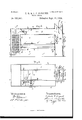
- Figure 1 is a side elevation of a drying machine constructed according to our invention.
- Fig. 2 is a top plan view of the same.
- Fig. 3 is a longitudinal section of the same through the line w-w of Fig. 2.
- Fig. 4 is an enlarged view of a part of Fig. 2, showing the operation of the eccentric which works the damper.
- Fig. 5 is a side elevation of Fig. 4. with the parts in front of the dotted line z-z removed for clearness of illustration.
- A is the outer casing of the drier, which incloses it completely and is provided with a door, a, in one side of it for introducing the fiber to be dried.
- a is a passageway outward to allow the air to escape, and is provided with a damper, a operated by a crank, 0. turning on pivots in the casing A.
- G is a slide damper or covering for the opening G, through which air is admitted to the drier when it is opened, and by sliding this damper to and fro by hand the amount of air admitted may be regulated as desired.
- e is a vertical air passage at one end of the drier and F is a horizontal air passage or tube extending on top of the drier throughout its length; these passages being connected together as shown in Fig. 3.
- a partition A reaching from the top of the main part of the drier down toward its bottom part, so as to leave a passageway, 6 underneath its lower endand partition off a space, I, in one end of the drier, which is connected with the passageway F at the top.
- H is a damper or valve in the passageway F, between this space and the opening G, by which the passage may be closed when de- Serial No. 351,880. (No model.)
- This damper turns on a shaft, h, pivoted in the side walls of the passageway and having attached near its outer end the arm R which is provided with the weight R
- Another arm 72 provided with" a Wrist pin is attached to the extreme outer end of shaft 71, to which wrist pin, the pitman bar, 71, is attached.
- This pitman bar is made in two parts screwed into the nut, 72 between them, so that it may be lengthened or shortened by screwing the parts farther in or out.
- This pitman bar is connected to the strap, 20, which embraces a cam on the shaft, 21.
- This shaft, 21, is mounted in stands, 22, 22, on top of the main part of the drier and revolved by the band wheel, 23, from a proper countershaft.
- the throw of the cam and its strap, 20, is such as to alternately open and close the damper H as the shaft 21 revolves.
- the Screen 0 On the inner faces of the casing A and partition A is secured the Screen 0 in a horizontal position, and at some distance below it the horizontal screen B is also arranged so as to have the fiber rest upon it during the drying process.
- the function of the screen 0 is to prevent the fiber from being drawn upward by the air current passing through the drier and carried away from the screen B.
- the screen B is supported upon a frame, I), which rests upon the bars 6 attached to the casing A and partition A, so that the screen B and its frame I) may be slid outward and inward on these bars, and the door a in the side of the drier is opened to allow the screen B to be withdrawn and replaced, when the fiber that is dried is to be removed and fresh fiber placed upon the screen for drying.
- the door a closes tightly so as to prevent the admission of air around it when it is closed, and the valve H also closes tightly.
- the casing A has a circular hole cut in it, opening into the passage e, and in this hole is mounted the fan, (1, so as to fill it.
- This fan is supported on a shaft, 30, in boxes in the stands, d one of which is attached to the cross bar, (1 extending across and attached to the walls of the passage c, and the other stand (1 is attached to the cross bar, at, which is fastened to the horizontal frame pieces d (Z and the upright posts (1; the whole of these (1, d d d constituting a frame to resist the strain of the running fan.
- the shaft 30 is revolved by the pulley, 31, which is driven from any suitable countershaft.
- the fan cl When the damper II is closed the fan cl partially exhausts the air fromthe inside of the drier, all its casing being so tightly fitted as to prevent the ingress of air through the joints, and this exhaustion of the air causes the moisture of the fiber being dried on the screen B to be taken up more rapidly by the rarefied air remaining in the drier.
- the damper II being then opened as well as the slide G, the sudden inrush of air carries the moisture-laden air within the drier out through the passage e and passageway outward (1 the damper a being of course left open during this process.
- the fan (Z is run at such a speed that the alternate opening and closing of the damper II thus causes an alternate partial exhaustion of the air in the drier and admission of air through passage F, which greatly accelerates the drying process.
- the damper a is closed or almost closed, the slide Gis closed or almost closed, and the damper H is opened, which allows the air to pass around continually, by the action of the fan (1, from the inside of the drier through the passages e, F, and space I. If the damper a and slide G are entirely closed, all the air will pass around. If they are left slightly open part of it will escape during its passage and its place be supplied with fresh air past the partly opened slide G.
- ⁇ Ve are thus enabled to use the drier with the stationary screen B to great advantage and in a variety of ways, as may be desired for operation in drying ditfcrent grades of wool, or for drying it in a greater or less degree.
- the slide G is held in guide-ways undercut in the strips g, which are attached to the casing.
- cam strap 20 is provided with slots, 40, in its sides, through which the shaft 21 runs, the position of these slots being such that as the weight, If, holds the damper H closed, the shaft will be in one end of the slots 40.
- cam, 41 as it revolves, however, having come in contact with the strap through a portion of its revolution pushes the latter along upon the shaft, moving the pitman endwise and overcoming the weight 7L3, opens the damper H. As the revolution of the cam continues it is withdrawn from the strap and the weight k closes the damper by sliding the strap along on the eccentric shaft 21.
- ⁇ Vhat we claim as new and of our invention is 1.
Landscapes
- Engineering & Computer Science (AREA)
- Textile Engineering (AREA)
- Mechanical Engineering (AREA)
- General Engineering & Computer Science (AREA)
- Drying Of Solid Materials (AREA)
Description
(No Model). 2 SheetsSheet 1, F. G. & A. G. SARGENT.
FIBER DRIER. No. 525,967. Patented Sept. 11, 1894.
W a O aha! A 9y Wfinmsem lmemnms'.
w 6. Q. fl fiohfl w @M 1% (No Model.) I 2 Sheets-Sheet 2.
F. G. & A). SARGRNT.
FIBER DRIER.
No. 525,967. Patented Sept. 11, 1894.
' W W JW "m: "cams PETERS 00.. mom-Lima. wasnmamn. n. c.
UNITED STATES PATENT OFFICE.
MASSACHUSETTS.
FIBER-DRIER.
SPECIFICATION forming part of Letters Patent No. 525,967, dated September Application filed May 15, 1 890.
To all whom it may concern.-
Be it known that We, FREDERICK G. SAR- GENT and ALLAN (J. SARGENT, of Graniteville, in the county of Middlesex and State of Massachusetts, have invented a new and useful Improvement in Fiber-Driers, ofwhich the following is a specification.
Our improvement relates to machines for drying fiber, and it consists in certain new and useful constructions and combinations of certain parts thereof substantially as hereinafter described and claimed.
In the drawings: Figure 1 is a side elevation of a drying machine constructed according to our invention. Fig. 2 is a top plan view of the same. Fig. 3 is a longitudinal section of the same through the line w-w of Fig. 2. Fig. 4 is an enlarged view of a part of Fig. 2, showing the operation of the eccentric which works the damper. Fig. 5 is a side elevation of Fig. 4. with the parts in front of the dotted line z-z removed for clearness of illustration. I I
A is the outer casing of the drier, which incloses it completely and is provided with a door, a, in one side of it for introducing the fiber to be dried.
a, is a passageway outward to allow the air to escape, and is provided with a damper, a operated by a crank, 0. turning on pivots in the casing A.
G is a slide damper or covering for the opening G, through which air is admitted to the drier when it is opened, and by sliding this damper to and fro by hand the amount of air admitted may be regulated as desired.
e is a vertical air passage at one end of the drier and F is a horizontal air passage or tube extending on top of the drier throughout its length; these passages being connected together as shown in Fig. 3. Across the drier internally, extending from side to side, is a partition A, reaching from the top of the main part of the drier down toward its bottom part, so as to leave a passageway, 6 underneath its lower endand partition off a space, I, in one end of the drier, which is connected with the passageway F at the top.
H is a damper or valve in the passageway F, between this space and the opening G, by which the passage may be closed when de- Serial No. 351,880. (No model.)
sired. This damper turns on a shaft, h, pivoted in the side walls of the passageway and having attached near its outer end the arm R which is provided with the weight R Another arm 72 provided with" a Wrist pin is attached to the extreme outer end of shaft 71, to which wrist pin, the pitman bar, 71, is attached. This pitman bar is made in two parts screwed into the nut, 72 between them, so that it may be lengthened or shortened by screwing the parts farther in or out. This pitman bar is connected to the strap, 20, which embraces a cam on the shaft, 21. This shaft, 21, is mounted in stands, 22, 22, on top of the main part of the drier and revolved by the band wheel, 23, from a proper countershaft. The throw of the cam and its strap, 20, is such as to alternately open and close the damper H as the shaft 21 revolves.
In the space I is located the steam pipes c, 0, arranged in the form of a heater or radiator for heating the air which passes through this space, which are to be connected to a boiler by the pipes c, 0 in the usual manner for supplying them with steam.
On the inner faces of the casing A and partition A is secured the Screen 0 in a horizontal position, and at some distance below it the horizontal screen B is also arranged so as to have the fiber rest upon it during the drying process. The function of the screen 0 is to prevent the fiber from being drawn upward by the air current passing through the drier and carried away from the screen B. The screen B is supported upon a frame, I), which rests upon the bars 6 attached to the casing A and partition A, so that the screen B and its frame I) may be slid outward and inward on these bars, and the door a in the side of the drier is opened to allow the screen B to be withdrawn and replaced, when the fiber that is dried is to be removed and fresh fiber placed upon the screen for drying. The door a closes tightly so as to prevent the admission of air around it when it is closed, and the valve H also closes tightly.
In one end of the drier the casing A has a circular hole cut in it, opening into the passage e, and in this hole is mounted the fan, (1, so as to fill it. This fan is supported on a shaft, 30, in boxes in the stands, d one of which is attached to the cross bar, (1 extending across and attached to the walls of the passage c, and the other stand (1 is attached to the cross bar, at, which is fastened to the horizontal frame pieces d (Z and the upright posts (1; the whole of these (1, d d d constituting a frame to resist the strain of the running fan. The shaft 30 is revolved by the pulley, 31, which is driven from any suitable countershaft. When the damper II is closed the fan cl partially exhausts the air fromthe inside of the drier, all its casing being so tightly fitted as to prevent the ingress of air through the joints, and this exhaustion of the air causes the moisture of the fiber being dried on the screen B to be taken up more rapidly by the rarefied air remaining in the drier. The damper II being then opened as well as the slide G, the sudden inrush of air carries the moisture-laden air within the drier out through the passage e and passageway outward (1 the damper a being of course left open during this process. The fan (Z is run at such a speed that the alternate opening and closing of the damper II thus causes an alternate partial exhaustion of the air in the drier and admission of air through passage F, which greatly accelerates the drying process.
In case it is desired to use the air several times over through the drier, the damper a" is closed or almost closed, the slide Gis closed or almost closed, and the damper H is opened, which allows the air to pass around continually, by the action of the fan (1, from the inside of the drier through the passages e, F, and space I. If the damper a and slide G are entirely closed, all the air will pass around. If they are left slightly open part of it will escape during its passage and its place be supplied with fresh air past the partly opened slide G. \Ve are thus enabled to use the drier with the stationary screen B to great advantage and in a variety of ways, as may be desired for operation in drying ditfcrent grades of wool, or for drying it in a greater or less degree. The slide G is held in guide-ways undercut in the strips g, which are attached to the casing.
The detail construction of the cam strap, 20, and shaft 21 is shown in Figs. 4 and 5. The cam strap 20 is provided with slots, 40, in its sides, through which the shaft 21 runs, the position of these slots being such that as the weight, If, holds the damper H closed, the shaft will be in one end of the slots 40. The
cam, 41, as it revolves, however, having come in contact with the strap through a portion of its revolution pushes the latter along upon the shaft, moving the pitman endwise and overcoming the weight 7L3, opens the damper H. As the revolution of the cam continues it is withdrawn from the strap and the weight k closes the damper by sliding the strap along on the eccentric shaft 21.
\Vhat we claim as new and of our invention is 1. The combination of a drying chamber; a screen placed horizontally within it and dividing it into upper and lower portions; an air inlet passage provided with a damper, leading into the chamber. on one side of the screens; an air outlet passage, provided with an exhaust fan, leading out of the chamber from the other side of the screen; and means for operating the damper and fan so as alternately to exhaust the air from the chamber through the screen and to admit fresh air thereto.
2. The combination of a drying chamber; two parallel screens placed horizontally within it and dividing it into upper and lower portions; an air inlet passage provided with a damper, leading into the chamber on one side of both screens; an air outlet passage, provided with an exhaust fan, leading out of the chamber from the other side of both screens; and means for operating the damper and fan so as alternately to exhaust the air from the chamber through the screens and to admit fresh air thereto.
3. The combination of a drying chamber; a screen for carrying the material to be dried, placed horizontally within it; an ingress passage, provided with a damper, leading into the chamber on one side of the screen; an egress passage, provided with an outlet with a damper therein, leading out of the chamber from the other side of the screen and connecting with the ingress passage; and a means of moving air through the passages and chamber, located in the air outlet passage.
4. The combination of a drying chamber; a screen for carrying the material to be dried, placed horizontally Within it; an ingress passage, provided with a damper and with an inlet regulated by a slide, leading into the chamber on one side of the screen; an egress passage, provided with an outlet with a damper therein, leading out of the chamber from the other side of the screen and connecting with the ingress passage; and a means of moving air through the passages and chamber, located in the air outlet passage.
FREDERICK G. SARGENT. v
ALLAN O. SARGENT.
Witnesses:
ARTHUR B. PLIMPTON, W. A. HARRIS.
Publications (1)
| Publication Number | Publication Date |
|---|---|
| US525967A true US525967A (en) | 1894-09-11 |
Family
ID=2594757
Family Applications (1)
| Application Number | Title | Priority Date | Filing Date |
|---|---|---|---|
| US525967D Expired - Lifetime US525967A (en) | Fiber-drier |
Country Status (1)
| Country | Link |
|---|---|
| US (1) | US525967A (en) |
-
0
- US US525967D patent/US525967A/en not_active Expired - Lifetime
Similar Documents
| Publication | Publication Date | Title |
|---|---|---|
| US525967A (en) | Fiber-drier | |
| US1028899A (en) | Grain-drier. | |
| US645366A (en) | Drying apparatus. | |
| US1259675A (en) | Drying-machine. | |
| US901191A (en) | Drier. | |
| US355559A (en) | sargent | |
| US1947338A (en) | Drier | |
| US2246252A (en) | Drying apparatus | |
| US1136645A (en) | Drying apparatus. | |
| US663418A (en) | Grain-drier. | |
| US527721A (en) | Fiber-drying machine | |
| US433094A (en) | Sylvania | |
| US521824A (en) | Fiber-drier | |
| US1165774A (en) | Drier. | |
| US185007A (en) | Improvement in fruit-driers | |
| US1281667A (en) | Drying-machine for fibrous materials. | |
| US307873A (en) | Wool-drier | |
| US426321A (en) | Sylvania | |
| US113157A (en) | Improvement in feather-renovators | |
| US327198A (en) | Gentand allas c | |
| US432282A (en) | Sylvania | |
| US525921A (en) | prootor | |
| US541652A (en) | Fruit-drier | |
| US253609A (en) | johnston | |
| US436032A (en) | Machine for manipulating fine-cut tobacco |