US5259456A - Drill stem test tools - Google Patents
Drill stem test tools Download PDFInfo
- Publication number
- US5259456A US5259456A US07/768,516 US76851691A US5259456A US 5259456 A US5259456 A US 5259456A US 76851691 A US76851691 A US 76851691A US 5259456 A US5259456 A US 5259456A
- Authority
- US
- United States
- Prior art keywords
- pressure
- chamber
- piston
- tubing
- valve
- Prior art date
- Legal status (The legal status is an assumption and is not a legal conclusion. Google has not performed a legal analysis and makes no representation as to the accuracy of the status listed.)
- Expired - Fee Related
Links
- 238000012360 testing method Methods 0.000 title claims abstract description 55
- 239000007788 liquid Substances 0.000 claims abstract description 89
- 230000007246 mechanism Effects 0.000 claims abstract description 19
- 230000000694 effects Effects 0.000 claims abstract description 13
- 238000007667 floating Methods 0.000 claims description 17
- 230000009467 reduction Effects 0.000 claims description 5
- 238000007789 sealing Methods 0.000 claims description 5
- 238000011144 upstream manufacturing Methods 0.000 claims description 4
- 230000002706 hydrostatic effect Effects 0.000 abstract description 27
- 230000015572 biosynthetic process Effects 0.000 abstract description 20
- 239000003129 oil well Substances 0.000 abstract description 4
- 238000004519 manufacturing process Methods 0.000 abstract description 3
- 238000012423 maintenance Methods 0.000 abstract description 2
- 239000007789 gas Substances 0.000 description 84
- 238000005755 formation reaction Methods 0.000 description 19
- 239000012530 fluid Substances 0.000 description 13
- 238000005553 drilling Methods 0.000 description 11
- 238000000034 method Methods 0.000 description 5
- IJGRMHOSHXDMSA-UHFFFAOYSA-N Atomic nitrogen Chemical compound N#N IJGRMHOSHXDMSA-UHFFFAOYSA-N 0.000 description 4
- 238000004891 communication Methods 0.000 description 4
- 239000003921 oil Substances 0.000 description 4
- 238000005086 pumping Methods 0.000 description 4
- 230000000638 stimulation Effects 0.000 description 4
- 239000002253 acid Substances 0.000 description 3
- 230000008602 contraction Effects 0.000 description 3
- 229920001971 elastomer Polymers 0.000 description 3
- 239000000806 elastomer Substances 0.000 description 3
- 239000004215 Carbon black (E152) Substances 0.000 description 2
- 230000008859 change Effects 0.000 description 2
- 238000010276 construction Methods 0.000 description 2
- 229930195733 hydrocarbon Natural products 0.000 description 2
- 229910052757 nitrogen Inorganic materials 0.000 description 2
- 230000009972 noncorrosive effect Effects 0.000 description 2
- 231100000252 nontoxic Toxicity 0.000 description 2
- 230000003000 nontoxic effect Effects 0.000 description 2
- 230000008569 process Effects 0.000 description 2
- 238000012546 transfer Methods 0.000 description 2
- 229910001339 C alloy Inorganic materials 0.000 description 1
- 229910000831 Steel Inorganic materials 0.000 description 1
- 230000009471 action Effects 0.000 description 1
- 230000003466 anti-cipated effect Effects 0.000 description 1
- 230000000903 blocking effect Effects 0.000 description 1
- 238000007906 compression Methods 0.000 description 1
- 238000001816 cooling Methods 0.000 description 1
- 230000003247 decreasing effect Effects 0.000 description 1
- 230000007613 environmental effect Effects 0.000 description 1
- 239000002360 explosive Substances 0.000 description 1
- 238000010438 heat treatment Methods 0.000 description 1
- 150000002430 hydrocarbons Chemical class 0.000 description 1
- 125000001183 hydrocarbyl group Chemical group 0.000 description 1
- 229910001026 inconel Inorganic materials 0.000 description 1
- 230000004941 influx Effects 0.000 description 1
- 239000000463 material Substances 0.000 description 1
- 238000005259 measurement Methods 0.000 description 1
- 230000004044 response Effects 0.000 description 1
- 239000011435 rock Substances 0.000 description 1
- 229920002545 silicone oil Polymers 0.000 description 1
- 230000003068 static effect Effects 0.000 description 1
- 239000010959 steel Substances 0.000 description 1
- 239000000126 substance Substances 0.000 description 1
- 238000012956 testing procedure Methods 0.000 description 1
- 238000013022 venting Methods 0.000 description 1
- XLYOFNOQVPJJNP-UHFFFAOYSA-N water Substances O XLYOFNOQVPJJNP-UHFFFAOYSA-N 0.000 description 1
Images


Classifications
-
- E—FIXED CONSTRUCTIONS
- E21—EARTH OR ROCK DRILLING; MINING
- E21B—EARTH OR ROCK DRILLING; OBTAINING OIL, GAS, WATER, SOLUBLE OR MELTABLE MATERIALS OR A SLURRY OF MINERALS FROM WELLS
- E21B34/00—Valve arrangements for boreholes or wells
- E21B34/06—Valve arrangements for boreholes or wells in wells
- E21B34/10—Valve arrangements for boreholes or wells in wells operated by control fluid supplied from outside the borehole
- E21B34/108—Valve arrangements for boreholes or wells in wells operated by control fluid supplied from outside the borehole with time delay systems, e.g. hydraulic impedance mechanisms
Definitions
- This invention relates to tools used in the testing of subterranean wells, and concerns in particular the mechanism by which such tools--especially but not exclusively those for use in hydrocarbon-bearing wells--are operated.
- casing the introduction and cementing into position of piping which will serve to support and line the bore
- One essential component of the test string is a valve known as the downhole valve, which is used to control the flow of fluid out of the formation and into and up the well tubing.
- the density of drilling fluid in the tubing above this valve is adjusted such that its hydrostatic pressure at the depth of the formation is lower than the formation fluid pressure.
- formation fluid is permitted to enter the well bore through perforations in the casing and flow into the tubing string (and possibly to the surface therethrough).
- the operation of the various tools included in the downhole test string including the opening and closing of the downhole valve itself--and, consequently, the control of the testing procedure--can be effected using one of three main types of mechanism. These types are those actuated by reciprocal motion of the pipe string (the inner tube, of which the test string constitutes a part), by rotational motion of the pipe string, or by changes in the pressure differential between the tubing and the annular space which surrounds it in the well--hereinafter referred to simply as "the annulus". Test strings wherein the tools thereof are activated by changes in annulus pressure are at present much in vogue, and it is this type of mechanism with which the invention is particularly concerned.
- a mechanism of the annulus pressure-responsive type requires the provision and maintenance of a fixed "reference" pressure within the tool. This, used in conjunction with an adjustable (and higher) annulus pressure, allows the establishment of the chosen pressure differential necessary to control the operation of the appropriate component of the test string.
- a convenient such pressure to trap is the hydrostatic ambient (annulus) pressure experienced by the string after it has been lowered down the well bore and set into the packer.
- This annulus pressure may, through a suitable connection, be communicated to a gas-filled pressure chamber within the string.
- the reference pressure must be isolated from both the annulus and the tubing so that fluctuations in the pressures therein will not affect the reference pressure.
- a pumping operation of this kind will cause the reference pressure to drop, due to contraction of the gas as it cools, unless some provision is made to maintain it--and, furthermore, the pressure will rise again once the pumping has ceased unless once more it is adjusted.
- Analogous problems can similarly occur during the pumping (albeit rare) of hot fluids to the formation--for example, to help remove waxy deposits blocking the perforations in the casing.
- the invention seeks to provide.
- the invention proposes that reference pressure within the test string be trapped by a novel mechanism wherein a valve drivable into a closed position by a first piston open to annulus pressure first defines, and then defines and closes, the open-to-tubing-pressure entrance to a passageway leading to a reference-gas-containing chamber via a second piston therewithin.
- tubing pressure is in equilibrium with annulus pressure, and is communicated via the passageway entrance and the chamber-contained piston to the reference gas, and secondly, after the test string has been stabbed into the packer, so isolating tubing pressure from annulus pressure, a momentary increase in annulus pressure will cause the first piston to move to drive the valve into the passageway-closed position, thus effectively sealing off the trapped reference gas from any further pressure changes.
- the invention proposes a new mechanism by which compensation can be made for the effect of downhole temperature changes on the gas in a reference pressure chamber, in which mechanism there is a hydraulic-liquid-containing chamber which is connected at one end, via a piston thereat, to a vent to annulus and at the other end to two "one-way" passageways linking it to the reference-gas-containing chamber via a chamber-contained second piston.
- this mechanism upon cooling (and thus contraction and pressure reduction) of the reference gas the resultant excess annulus liquid pressure is communicated to, and exerted on, the second piston via the first piston and the hydraulic liquid, thus causing a movement of the second piston which will re-compress the gas and restore reference pressure.
- the resultant excess gas pressure is communicated to, and exerted upon, the first piston via the second piston and the hydraulic liquid, thus causing a movement of the first piston to vent chamber-contained annulus fluid, and thereby allowing movement of the second piston which will decompress the gas and restore reference pressure.
- this invention provides a reference pressure tool containing therewithin a chamber holding a reference pressure gas and having means for trapping ambient pressure therein, which trapping means comprises:
- valve body a passageway defined by the valve body, and closed by the valve when the latter is in its closed position, which passageway has an entrance open to tubing pressure and leads to the reference-gas-containing chamber via a chamber-contained second piston;
- tubing pressure is communicated to the reference gas, via the passageway entrance and the chamber-contained piston, until an applied increase in annulus pressure over tubing pressure causes the first piston to move to drive the valve into the passageway-closed position, thus effectively sealing off the trapped reference gas from any further pressure changes.
- this invention provides a reference pressure tool containing therewithin a chamber holding a reference pressure gas and having means for compensating for the effect of temperature changes on the gas, which compensation means comprises:
- a hydraulic-liquid-containing chamber connected at one end, via a piston thereat, to a vent to annulus;
- the invention provides a reference pressure tool incorporating means for trapping ambient tubing pressure within a reference gas chamber therein.
- the chamber might be of any shape, configuration and size, it is most conveniently an annular chamber constructed within the walls of the test tubing. These walls are about 1 cm (0.5 in) thick; it is relatively easy to provide therewithin an annular chamber having a "cross sectional" thickness of around 1 cm (0.5 in).
- the size (volume) of the chamber this naturally depends on the number of tools that the test string incorporates and that are operated by pressurised liquid derived ultimately from the gas in the chamber. In general, however, it will be desirable to have at least 13 liters (800 in 3 ) of pressurised reference gas.
- the reference pressure gas itself may be any gas that is both capable of remaining gaseous under the downhole ambient conditions and non-toxic and non-corrosive. That gas commonly used is nitrogen. While this gas may be introduced into the pressure chamber at normal pressures (that is to say, at 1 atmosphere), it is in fact much preferred to pump the gas in at a higher pressure--in the neighbourhood of 135 Bar (2000 psi)--which ensures that the relevant floating piston(s) will have sufficient freedom of movement at the test string's planned operating depth.
- the reference pressure tool of the invention allows ambient tubing pressure at the operating depth to be trapped and utilised thereafter as a reference pressure against which annulus pressure can be used to provide an excess pressure to operate the various tools in the test string.
- the trapping means comprises a piston-driven valve defining (and closing) a passageway open to tubing pressure and leading via another piston to the gas chamber.
- the gas chamber can be of any form but is preferably annular, being constructed within the tube walls, so the other major components of the trapping means are similarly preferably annular, fitting within or adjacent the tube walls.
- the valve is most conveniently a sleeve valve, internally mounted of the tubing and sliding along the tube from an initial open position to a final closed position, and comprising a tubular valve body bearing a valve member which is itself a ring seal that is moved along to and into contact with an internal tubing wall (defining the passageway, as discussed below).
- the first piston (which is conveniently a "floating" piston without a con-rod connecting it to any other part of the tool) is also most conveniently annular.
- a piston conventionally mounted between the oppssing side walls of a chamber
- a step-form sleeve piston-- that is to say, a piston in the form of a sliding sleeve halfway along the sliding face of which is a step effectively constituting the driven face thereof (against which pressure is applied to drive the piston), both the thicker and thinner sleeve portions above and below the step having ring seals that seal the piston to the surface against which it slides.
- a stepped sliding-sleeve piston is shown in the accompanying Drawings, and described hereinafter.
- the piston can drive the valve in any convenient way.
- it in effect it merely abuts one end of the valve body, and in operation simply pushes the valve body from its "open” to its "closed” position.
- the valve body together with an internal surface of the tube, defines part--an annular part--of an internal passageway the rest of which may be a narrow "pipe" formed within the tube walls.
- This passageway in operation can flow annulus fluid contained within the tube--unless, of course the valve has moved to its "closed” position, in which case the passageway is sealed shut by the valve member itself.
- This passageway is open at one end to the inside of the tube, and thus to tubing pressure, and the necessary opening is conveniently at the "annular" portion end--and, indeed, by way of an aperture in and through the valve body.
- the passageway opens into the reference pressure gas chamber, but a direct connection between the passageway and the gas in the chamber is prevented by a piston--in the preferred case, a floating annular piston--operatively mounted within the gas chamber at or adjacent the passageway's opening thereto.
- non-return valve preventing the flow of passageway-contained tubing liquid back towards (and possibly out of) the end of the passageway open to tubing pressure. This prevents loss of reference pressure immediately after stabbing-in should the formation pressure be less than annulus pressure (as may sometimes be the case).
- the non-return valve may take any convenient form, but preferably it is annular, mounted within an annular valve chamber forming a widened part of the annular portion of the passageway to the gas chamber, and spring-loaded into a position where it closes off the egress of the upstream section of the passageway into the valve chamber.
- the open-ended test string containing the reference pressure tool is lowered slowly into the well bore, and as this occurs tubing pressure is communicated to the reference gas via the passageway entrance and the chamber-contained piston, whereupon drilling liquid (tubing and annulus) pressure will act both upon the first, valve-driving piston and upon the second, gas-chamber-contained piston (in the latter case, via the passageway opening from the tubing).
- drilling liquid tubing and annulus
- the tool is not affected in any way until it has been lowered beyond the depth at which the downhole hydrostatic pressure exerted by the drilling liquid exceeds the pressure of the pre-pressurized reference gas within the chamber.
- the excess liquid pressure subsequently exerted on the reference gas via the chamber-contained piston progressively compresses the reference gas so that the pressure thereof is always equal to the ambient hydrostatic pressure. This compression process continues until the required test depth is reached, whereupon the test string is "stabbed in” to the packer--that is to say, it is sealingly lodged therein--thus isolating, for the first time, the tubing of the tool from the annulus.
- the required reference pressure contained within the gas chamber must be trapped by driving the valve into its closed position. This is achieved by momentarily increasing annulus pressure over tubing pressure. This new increased pressure--applied to the annulus from the head of the well in any convenient way--creates a pressure differential across the valve-driving piston, which now experiences hydrostatic (tubing) pressure on one side and the applied (and higher) annulus pressure on the other. The piston therefore moves, and as it does so drives the valve into its closed position, thus sealing the passageway leading to the reference gas chamber, and so effectively isolating the gas therein from any further pressure changes.
- the reference pressure tool of the invention incorporates a mechanism by which the excess tubing pressure generated on stabbing-in can be bled off to annulus without being communicated to the reference gas chamber.
- That mechanism conveniently employs a one-way bleed valve opening to annulus and positioned along the passageway to the reference gas chamber, which bleed valve opens whenever tubing pressure markedly exceeds annulus pressure by some pre-set value.
- the relative positioning of the two valves along the passageway may be such that the bleed valve is either upstream or downstream of the non-return valve, though having regard to the limited space available the valve is very preferably an annular valve (like the non-return valve) situated upstream.
- the bleed valve is preferably co-axial with the non-return valve's chamber, and operatively connected between the latter chamber and a port to annulus, spring-loaded into a position where it blocks the egress of the connection to the latter chamber, and so prevents ingress of liquid thereinto.
- the invention also provides a reference pressure tool incorporating a gas-filled reference pressure chamber.
- a reference pressure tool incorporating a gas-filled reference pressure chamber.
- This second reference pressure tool includes means for compensating for the effect of temperature changes on the gas--specifically, means utilising a chamber of hydraulic liquid connected at one end (via a piston thereat) to a port to annulus, and at the other to another piston in the reference gas chamber via two "one-way" passageways.
- the liquid chamber is conveniently annular, and constructed within the tube walls in much the same way as the reference gas chamber. Its dimensions, and hence the volume of fluid contained therewithin, depend at least in part on the magnitude of the temperature range that is anticipated. Generally, however, a volume of 13 liters (800 in 3 ) will be sufficient.
- the hydraulic liquid requires no special properties save those of remaining liquid in all foreseeable circumstances, and of being generally inert-- non-toxic, non-corrosive, and, especially, non-explosive.
- Suitable liquids are silicone oils, as is well known in the Art.
- the piston separating the liquid chamber from the port to annulus is, in a preferred embodiment of the invention, another annular, floating piston.
- the liquid chamber is linked at its other end (the end not connected to the port to annulus) to two passageways leading to a piston within the reference gas chamber.
- the gas chamber will thus be bounded by two pistons (conveniently both of the floating annular kind), one of which is adjacent the open-to-tubing passageway required for the trapping of reference pressure, and the other of which links (indirectly) the gas chamber to the hydraulic liquid chamber.
- Each passageway has within its length a one-way valve, very preferably of a pressure-sensitive variety. Not only does this valve permit only unidirectional flow therethrough (and the arrangement is such that one passageway allows flow only in one direction whilst the other allows flow only in the other direction), but in addition the flow is restricted to an extremely low rate (about 1 cc per 10 minutes) regardless of the pressure drop across the valve (the reason for this is discussed hereinafter in more detail with reference to the Drawings, but briefly it is to prevent sudden annulus pressure changes which affect the pressure of the hydraulic liquid from further affecting the pressure of the gas in the reference pressure chamber connected thereto).
- Valves of this one-way, restrictor nature are well known, and commercially available.
- any reduction in the ambient temperature-- such as might occur during a stimulation with cold acid--will in the first instance cause the pressure of the gas within the reference pressure chamber to drop (initially the volume of the gas notionally stays the same--it is that volume contained within the piston-bounded chamber).
- the reference pressure were to remain at this reduced level problems would arise in operating the test string because the application to the annulus liquid of a pressure a specific amount higher than the expected reference pressure (in order to create the pressure differential by which one of the tools is activated) would no longer necessarily have the desired effect when measured against the now reduced reference pressure.
- a (thermally-induced) pressure drop of this nature gives rise to a pressure differential across the gas-chamber-contained piston of the temperature compensation means.
- this piston experiences the reduced gas pressure, and on the other it experiences the unchanged (and therefore higher) hydrostatic--that is, annulus--pressure which is being communicated to it via the hydraulic-liquid-filled passageway and chamber and the open-to-annulus piston.
- the gas-chamber piston therefore moves under the influence of the excess liquid pressure in such a way that the volume of the reference gas chamber bounded thereby is decreased.
- the pressure of the gas within the chamber thus increases until it once more equals the original hydrostatic (reference) pressure. In this way the correct operation of the test string in response to applied annulus pressure is ensured even during a drop in ambient downhole temperature.
- the described temperature reduction may eventually be reversed (as when, for example, acid stimulation ceases, and the ambient temperature increases to the normal, "background” level), and when this happens the resulting increase in reference gas pressure (as the gas heats up) must suitably be allowed for.
- the mechanism of the invention there will now be a pressure differential across that piston between the gas chamber and the liquid chamber such that the higher pressure is that exerted by the reference gas.
- the piston thus moves to allow the gas to expand (thereby reducing its pressure).
- the hydraulic liquid is pushed through the passageway and liquid chamber, and in turn drives the open-to-annulus piston to vent annulus liquid from the tool--a process that continues until reference pressure has been restored to the desired value.
- any temperature variation--and, indeed, any sequence of such variations--occurring down the well can be suitably compensated by adjustments of the types just described, thereby ensuring that the pressure differential required for test tool operation may always correctly be achieved by application of a previously-calculated annulus pressure.
- the materials employed in the construction of the various components of the two inventions hereinbefore described may be any of those normally utilised in the Art for similar construction.
- the tubing of the tool may be of a low carbon alloy steel
- the valve gear may be of any suitably non-corrodible substance (for example, INCONEL).
- FIG. 1 is a simplified cross sectional view of an offshore oil well with a test string including a tool of the invention
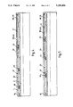
- FIGS. 2A/B show a tool of the invention as it appears in cross-section prior to stabbing into the packer
- FIGS. 3A/B show the tool of FIG. 2 after stabbing into the packer and applying a high annulus pressure
- FIG. 4 shows the B section of the tool of FIG. 2 after a drop in ambient downhole temperature
- FIG. 5 shows the B section of the tool of FIG. 2 after an increase in ambient downhole temperature.
- FIG. 1 shows a floating drilling rig (101, not shown in detail) from which has been drilled an oil well (generally 102) having a well bore (103) reaching down to a rock stratum constituting the formation (109) of interest.
- BOP blow-out preventer mechanism
- Cemented into the well bore 103 are a shallow casing (106) and a deep casing (107); the lower end of the latter has a multitude of perforations (as 108) permitting communication between the well bore 103 and the oil formation 109.
- test string (110) comprising tubing (113) ending in a set of test tools (see below).
- the string 110 is set at its lower end into a packer (111), and a seal sleeve (112) seals the packer 111 to the test string 110, thus isolating the tubing 113 thereof from the annulus (114).
- a gauge carrier which contains electronic or mechanical gauges (not shown) which collect downhole pressure and temperature data during the test sequence.
- the gauge carrier 115 contains electronic or mechanical gauges (not shown) which collect downhole pressure and temperature data during the test sequence.
- the constant pressure reference tool 117
- the downhole valve 118; the operation of which enables the test sequence to be carried out.
- a circulating sleeve 119 permits removal of any formation fluid remaining within the test string 110 prior to its withdrawal from the well bore 103.
- a subsea test tree 120 which serves both as a primary safety valve and as a support for the rest of the test string 110.
- FIGS. 2 to 5 show a constant pressure reference tool 117 of the invention having a main housing (1) and the tubing internal bore (2).
- a floating annular stepped sliding sleeve piston (3; shown hatched) which communicates with liquid (not shown) in the annulus (not shown specifically--it is the volume "outside" the housing 1) by way of a port (5) to annulus (the annulus liquid is applied to the face of a step halfway along the sleeve, and presses thereagainst so as in operation to drive the piston towards the right as shown).
- elastomer seals 32, 34.
- the floating piston 3 is in direct driving contact with a sliding (seal) sleeve valve (4; shown hatched) having elastomer seals (12) and which, when driven by the piston 3, is capable of movement (to the right as shown) along the annular chamber 10.
- a port (6) through the sleeve 4 permits communication between tubing 2 and annular chamber 10. Since, prior to stabbing in, the tubing 2 is open to annulus, the liquid pressures acting on each side of floating piston 3 through ports 5 and 6 are equal, and so no movement of piston 3 (or sleeve 4) occurs.
- a narrow annular passageway (30) leads from the annular chamber 10 to a one-way spring-loaded valve (13) which permits liquid flow therethrough once the force of its valve spring (15) has been overcome, but which prevents the return of this liquid.
- valve 13 Beyond valve 13 are another, pipe-like, passageway (19) and a further one-way spring-loaded valve (14) with an associated spring (16).
- the valve 14 will only allow liquid to pass through it if the pressure thereof markedly exceeds the pressure of the liquid in the annulus. Downstream of the valve 14 is a port (7) to annulus.
- Passageway 19 leads to an annular, reference-gas-containing reference pressure chamber (22; the gas is usually nitrogen), confined at either end by a floating piston (20, 23).
- a port (37) permits direct communication between gas chamber 22 and outside the tubing and the gas may be charged into the chamber 22 therethrough (after which the port is sealed up).
- These two valves 28, 29 are pressure-sensitive in that they remain open while the pressure across them stays below a certain, predetermined, threshold value, but close immediately that threshold value is reached or exceeded.
- valve 28 permits liquid flow along passageway 26a from chamber 27 towards piston 23 only, whereas valve 29 allows liquid flow away from piston 23 only.
- the gas within the reference pressure chamber 22 and the hydraulic liquid within chamber 27 are both adjusted to a pressure of 135 Bar (2000 psi).
- liquid in the annulus and tubing 2 surrounds the tool, enters the ports 5, 6, 7 and 24, and fills annular chamber 10 and passageway 19 (the liquid does not, however, pass valve 14 since the liquid pressures either side thereof--in tubing 2 and the annulus via port 7--are equal).
- the liquid does not at first enter the reference pressure chamber 22 or the hydraulic liquid chamber 27 because these have initial internal pressures greater than the hydrostatic pressure exerted by the well liquid.
- hydrostatic pressure will exceed the pressure of the reference gas and of the hydraulic liquid.
- This hydrostatic pressure will act upon the gas, having been communicated through port 6 to chamber 10 and along passageway 19 to piston 20.
- This piston will thus move along chamber 22, to pressurize the gas therein until pressure balance is restored (when the gas reaches hydrostatic pressure).
- well liquid entering port 24 will push piston 25 into the liquid chamber 27 until the pressures within the chamber and passageway 26a equal the instantaneous hydrostatic pressure (the pressure of the liquid within passageway 26b remains at its initial value due to the action of valve 29).
- valve 14 opens and excess liquid from within the tool is vented to the annulus via port 7 until tubing and hydrostatic pressures are again equal.
- the pressure of the gas within annular chamber 22 thus remains at the hydrostatic pressure--and indeed non-return valve 13 ensures that it does remain so even if, because of a low formation pressure, tubing pressure should drop below annulus hydrostatic pressure.
- FIGS. 4 and 5 show the effect on the tool of changes in downhole temperature.
- FIG. 4 shows the effect of a drop in downhole temperature. Any resultant (small) drop in the pressure of the hydraulic liquid within chamber 27 is rectified by movement of piston 25 initiated by the corresponding excess hydrostatic pressure exerted thereon by annulus liquid.
- the reference is, however, susceptible to a much more significant pressure drop. This results in pressure differentials arising across both of the gas-chamber-contained pistons 20 and 23 which drive these pistons towards each other, re-pressurizing the gas.
- Piston 20 will move only slightly (there is only a small volume of liquid behind it, and hence pressure balance thereacross is soon restored), but piston 23 will move as far as is necessary to re-establish the original reference pressure in the gas (the hydraulic liquid in passageway 26 and chamber 27 is always maintained at hydrostatic pressure by influx of annulus liquid at port 24 as just described).
- FIGS. 4 and 5 The effect of a rise in the ambient downhole temperature is shown in FIGS. 4 and 5.
- the reference gas pressure (and, much less significantly, that of the hydraulic liquid) also rises.
- the hydraulic liquid pressure is maintained by flow of annulus liquid through port 24.
- pressure differentials are created across floating pistons 20 and 23 which would tend to drive these pistons away from each other, to allow the reference pressure to adjust to the desired hydrostatic pressure.
- floating piston 23 reaches the upper end of the gas chamber 22 it is unable to move further to reduce the pressure differential across it.
- Restoration of the reference pressure to its original value must therefore be effected by movement of piston 20.
- the well liquid contained in the chamber 22 on the other side of the piston 20, and in passageway 19, is pressurized.
- valve 14 When its pressure exceeds hydrostatic pressure, valve 14 will open and vent excess liquid to the annulus via port 7 until equilibrium is reached.
Landscapes
- Geology (AREA)
- Life Sciences & Earth Sciences (AREA)
- Engineering & Computer Science (AREA)
- Mining & Mineral Resources (AREA)
- Environmental & Geological Engineering (AREA)
- Fluid Mechanics (AREA)
- Physics & Mathematics (AREA)
- General Life Sciences & Earth Sciences (AREA)
- Geochemistry & Mineralogy (AREA)
- Pipe Accessories (AREA)
- Testing Of Devices, Machine Parts, Or Other Structures Thereof (AREA)
- Investigating Strength Of Materials By Application Of Mechanical Stress (AREA)
- Measuring Fluid Pressure (AREA)
- Decoration Of Textiles (AREA)
- Earth Drilling (AREA)
Abstract
Description
Claims (17)
Applications Claiming Priority (2)
| Application Number | Priority Date | Filing Date | Title |
|---|---|---|---|
| GB8907098A GB2229748B (en) | 1989-03-29 | 1989-03-29 | Drill stem test tools |
| GB8907098 | 1989-03-29 |
Publications (1)
| Publication Number | Publication Date |
|---|---|
| US5259456A true US5259456A (en) | 1993-11-09 |
Family
ID=10654128
Family Applications (1)
| Application Number | Title | Priority Date | Filing Date |
|---|---|---|---|
| US07/768,516 Expired - Fee Related US5259456A (en) | 1989-03-29 | 1990-03-27 | Drill stem test tools |
Country Status (7)
| Country | Link |
|---|---|
| US (1) | US5259456A (en) |
| EP (1) | EP0465503B1 (en) |
| CA (1) | CA2049355C (en) |
| DK (1) | DK0465503T3 (en) |
| GB (2) | GB2229748B (en) |
| NO (1) | NO303030B1 (en) |
| WO (1) | WO1990011429A2 (en) |
Cited By (10)
| Publication number | Priority date | Publication date | Assignee | Title |
|---|---|---|---|---|
| WO2000063525A1 (en) * | 1999-04-15 | 2000-10-26 | Weatherford/Lamb, Inc. | Downhole tool with thermal compensation |
| US6557631B1 (en) * | 1999-10-30 | 2003-05-06 | Reeves Wireline Technologies, Ltd. | Down hole tension/compression device for logging tools |
| WO2006015277A1 (en) * | 2004-07-30 | 2006-02-09 | Baker Hughes Incorporated | Downhole inflow control device with shut-off feature |
| US20080135233A1 (en) * | 2006-12-08 | 2008-06-12 | Horton Technologies, Llc | Methods for Development of an Offshore Oil and Gas Field |
| US20100122811A1 (en) * | 2008-11-18 | 2010-05-20 | Chevron U.S.A. Inc. | Systems and methods for mitigating annular pressure buildup in an oil or gas well |
| US20110083859A1 (en) * | 2009-10-08 | 2011-04-14 | Schlumberger Technology Corporation | Downhole valve |
| WO2013025368A2 (en) | 2011-08-16 | 2013-02-21 | Baker Hughes Incorporated | Tubing pressure insensitive pressure compensated actuator for a downhole tool and method |
| US20130068472A1 (en) * | 2011-09-19 | 2013-03-21 | Baker Hughes Incorporated | Hydraulic Three Position Stroker Tool |
| CN110306976A (en) * | 2019-07-01 | 2019-10-08 | 西南石油大学 | Inert gas injection control annular pressure test device and its test method |
| CN116263387A (en) * | 2021-12-13 | 2023-06-16 | 中国石油天然气股份有限公司 | Apparatus and method for evaluating pressure bearing capacity of liquid rubber stopper |
Families Citing this family (8)
| Publication number | Priority date | Publication date | Assignee | Title |
|---|---|---|---|---|
| NO932900L (en) * | 1992-08-21 | 1994-02-22 | Ava Int Corp | Bridge safety valve |
| US5549162A (en) * | 1995-07-05 | 1996-08-27 | Western Atlas International, Inc. | Electric wireline formation testing tool having temperature stabilized sample tank |
| US9027640B2 (en) | 2004-05-19 | 2015-05-12 | Omega Completion Technology Ltd. | Method for signalling a downhole device in a well |
| GB0411121D0 (en) | 2004-05-19 | 2004-06-23 | Omega Completion Technology | Method for signalling a downhole device in a flowing well |
| GB0521917D0 (en) | 2005-10-27 | 2005-12-07 | Red Spider Technology Ltd | Improved pressure equalising device and method |
| GB0621031D0 (en) | 2006-10-24 | 2006-11-29 | Red Spider Technology Ltd | Downhole apparatus and method |
| US9279310B2 (en) * | 2013-01-22 | 2016-03-08 | Halliburton Energy Services, Inc. | Pressure testing valve and method of using the same |
| WO2019038643A1 (en) * | 2017-08-23 | 2019-02-28 | Vallourec Tube-Alloy, Llc | Device and method for mitigating annular pressure buildup in a wellbore casing annulus |
Citations (6)
| Publication number | Priority date | Publication date | Assignee | Title |
|---|---|---|---|---|
| US3976136A (en) * | 1975-06-20 | 1976-08-24 | Halliburton Company | Pressure operated isolation valve for use in a well testing apparatus and its method of operation |
| US4429748A (en) * | 1980-11-05 | 1984-02-07 | Halliburton Company | Low pressure responsive APR tester valve |
| US4448254A (en) * | 1982-03-04 | 1984-05-15 | Halliburton Company | Tester valve with silicone liquid spring |
| US4655288A (en) * | 1985-07-03 | 1987-04-07 | Halliburton Company | Lost-motion valve actuator |
| US4736798A (en) * | 1986-05-16 | 1988-04-12 | Halliburton Company | Rapid cycle annulus pressure responsive tester valve |
| US5101904A (en) * | 1991-03-15 | 1992-04-07 | Bruce Gilbert | Downhole tool actuator |
Family Cites Families (6)
| Publication number | Priority date | Publication date | Assignee | Title |
|---|---|---|---|---|
| US3856085A (en) * | 1973-11-15 | 1974-12-24 | Halliburton Co | Improved annulus pressure operated well testing apparatus and its method of operation |
| US3964544A (en) * | 1975-06-20 | 1976-06-22 | Halliburton Company | Pressure operated isolation valve for use in a well testing and treating apparatus, and its method of operation |
| US4125165A (en) * | 1977-07-21 | 1978-11-14 | Baker International Corporation | Annulus pressure controlled test valve with locking annulus pressure operated pressure trapping means |
| US4109725A (en) * | 1977-10-27 | 1978-08-29 | Halliburton Company | Self adjusting liquid spring operating apparatus and method for use in an oil well valve |
| US4664196A (en) * | 1985-10-28 | 1987-05-12 | Halliburton Company | Downhole tool with compressible liquid spring chamber |
| US4665991A (en) * | 1986-01-28 | 1987-05-19 | Halliburton Company | Downhole tool with gas energized compressible liquid spring |
-
1989
- 1989-03-29 GB GB8907098A patent/GB2229748B/en not_active Expired - Fee Related
-
1990
- 1990-03-27 US US07/768,516 patent/US5259456A/en not_active Expired - Fee Related
- 1990-03-27 WO PCT/GB1990/000455 patent/WO1990011429A2/en not_active Ceased
- 1990-03-27 CA CA002049355A patent/CA2049355C/en not_active Expired - Fee Related
- 1990-03-27 EP EP90904916A patent/EP0465503B1/en not_active Expired - Lifetime
- 1990-03-27 DK DK90904916.5T patent/DK0465503T3/en active
-
1991
- 1991-09-27 NO NO913810A patent/NO303030B1/en not_active IP Right Cessation
-
1992
- 1992-05-29 GB GB9211398A patent/GB2257181B/en not_active Expired - Fee Related
Patent Citations (6)
| Publication number | Priority date | Publication date | Assignee | Title |
|---|---|---|---|---|
| US3976136A (en) * | 1975-06-20 | 1976-08-24 | Halliburton Company | Pressure operated isolation valve for use in a well testing apparatus and its method of operation |
| US4429748A (en) * | 1980-11-05 | 1984-02-07 | Halliburton Company | Low pressure responsive APR tester valve |
| US4448254A (en) * | 1982-03-04 | 1984-05-15 | Halliburton Company | Tester valve with silicone liquid spring |
| US4655288A (en) * | 1985-07-03 | 1987-04-07 | Halliburton Company | Lost-motion valve actuator |
| US4736798A (en) * | 1986-05-16 | 1988-04-12 | Halliburton Company | Rapid cycle annulus pressure responsive tester valve |
| US5101904A (en) * | 1991-03-15 | 1992-04-07 | Bruce Gilbert | Downhole tool actuator |
Cited By (22)
| Publication number | Priority date | Publication date | Assignee | Title |
|---|---|---|---|---|
| WO2000063525A1 (en) * | 1999-04-15 | 2000-10-26 | Weatherford/Lamb, Inc. | Downhole tool with thermal compensation |
| US6305477B1 (en) | 1999-04-15 | 2001-10-23 | Weatherford International, Inc. | Apparatus and method for maintaining relatively uniform fluid pressure within an expandable well tool subjected to thermal variants |
| AU767191B2 (en) * | 1999-04-15 | 2003-11-06 | Weatherford Technology Holdings, Llc | Downhole tool with thermal compensation |
| US6557631B1 (en) * | 1999-10-30 | 2003-05-06 | Reeves Wireline Technologies, Ltd. | Down hole tension/compression device for logging tools |
| WO2006015277A1 (en) * | 2004-07-30 | 2006-02-09 | Baker Hughes Incorporated | Downhole inflow control device with shut-off feature |
| US8122965B2 (en) * | 2006-12-08 | 2012-02-28 | Horton Wison Deepwater, Inc. | Methods for development of an offshore oil and gas field |
| US20080135233A1 (en) * | 2006-12-08 | 2008-06-12 | Horton Technologies, Llc | Methods for Development of an Offshore Oil and Gas Field |
| CN102216557B (en) * | 2008-11-18 | 2014-09-24 | 雪佛龙美国公司 | Systems and methods for mitigating annular pressure buildup in an oil or gas well |
| US20100122811A1 (en) * | 2008-11-18 | 2010-05-20 | Chevron U.S.A. Inc. | Systems and methods for mitigating annular pressure buildup in an oil or gas well |
| US8066074B2 (en) * | 2008-11-18 | 2011-11-29 | Chevron U.S.A. Inc. | Systems and methods for mitigating annular pressure buildup in an oil or gas well |
| AU2009316726B2 (en) * | 2008-11-18 | 2015-10-22 | Chevron U.S.A. Inc. | Systems and methods for mitigating annular pressure buildup in an oil or gas well |
| GB2477670B (en) * | 2008-11-18 | 2013-02-13 | Chevron Usa | Systems and methods for mitigating annular pressure buildup in an oil or gas well |
| CN102216557A (en) * | 2008-11-18 | 2011-10-12 | 雪佛龙美国公司 | Systems and methods for mitigating annular pressure buildup in an oil or gas well |
| US20110083859A1 (en) * | 2009-10-08 | 2011-04-14 | Schlumberger Technology Corporation | Downhole valve |
| US9062514B2 (en) | 2009-10-08 | 2015-06-23 | Schlumberger Technology Corporation | Downhole valve |
| WO2013025368A2 (en) | 2011-08-16 | 2013-02-21 | Baker Hughes Incorporated | Tubing pressure insensitive pressure compensated actuator for a downhole tool and method |
| EP2744974A4 (en) * | 2011-08-16 | 2015-11-11 | Baker Hughes Inc | ACTUATOR CONTROLLED BY PRESSURE INSENSITIVE TO PRESSURE OF PRODUCTION RODS FOR DOWNHOLE TOOL AND METHOD |
| AU2012295401B2 (en) * | 2011-08-16 | 2016-08-11 | Baker Hughes Incorporated | Tubing pressure insensitive pressure compensated actuator for a downhole tool and method |
| US20130068472A1 (en) * | 2011-09-19 | 2013-03-21 | Baker Hughes Incorporated | Hydraulic Three Position Stroker Tool |
| CN110306976A (en) * | 2019-07-01 | 2019-10-08 | 西南石油大学 | Inert gas injection control annular pressure test device and its test method |
| CN110306976B (en) * | 2019-07-01 | 2022-03-08 | 西南石油大学 | Inert gas injection control annular pressure experiment device and method |
| CN116263387A (en) * | 2021-12-13 | 2023-06-16 | 中国石油天然气股份有限公司 | Apparatus and method for evaluating pressure bearing capacity of liquid rubber stopper |
Also Published As
| Publication number | Publication date |
|---|---|
| EP0465503B1 (en) | 1994-06-08 |
| NO913810D0 (en) | 1991-09-27 |
| GB2229748B (en) | 1993-03-24 |
| GB2257181B (en) | 1993-03-24 |
| GB9211398D0 (en) | 1992-07-15 |
| WO1990011429A2 (en) | 1990-10-04 |
| NO913810L (en) | 1991-11-27 |
| GB8907098D0 (en) | 1989-05-10 |
| WO1990011429A3 (en) | 1990-12-13 |
| EP0465503A1 (en) | 1992-01-15 |
| GB2257181A (en) | 1993-01-06 |
| GB2229748A (en) | 1990-10-03 |
| NO303030B1 (en) | 1998-05-18 |
| CA2049355A1 (en) | 1990-09-30 |
| DK0465503T3 (en) | 1994-11-07 |
| CA2049355C (en) | 1997-12-02 |
Similar Documents
| Publication | Publication Date | Title |
|---|---|---|
| US5259456A (en) | Drill stem test tools | |
| US4109724A (en) | Oil well testing valve with liquid spring | |
| US4429748A (en) | Low pressure responsive APR tester valve | |
| US4422506A (en) | Low pressure responsive APR tester valve | |
| EP0088550B1 (en) | Tester valve with liquid spring | |
| US4109725A (en) | Self adjusting liquid spring operating apparatus and method for use in an oil well valve | |
| US4444268A (en) | Tester valve with silicone liquid spring | |
| AU730419B2 (en) | Hydrostatic tool with electrically operated setting mechanism | |
| US5649597A (en) | Differential pressure test/bypass valve and method for using the same | |
| US4665983A (en) | Full bore sampler valve with time delay | |
| US4440230A (en) | Full-bore well tester with hydrostatic bias | |
| US4258793A (en) | Oil well testing string bypass valve | |
| EP0212814B1 (en) | Method of operating apr valve in wellbore | |
| US4665991A (en) | Downhole tool with gas energized compressible liquid spring | |
| US20040011519A1 (en) | Well pressure activated pack-off head | |
| NZ208833A (en) | Well,annulus pressure change operated valve:actuating piston held in actuated position by back pressure check valve | |
| US4655288A (en) | Lost-motion valve actuator | |
| US4281715A (en) | Bypass valve | |
| US3500911A (en) | Multiple packer distribution valve and method | |
| EP0470160B1 (en) | Well control apparatus | |
| US3459264A (en) | Pressure regulating valve assembly between open hole packers and method | |
| US3732925A (en) | Apparatus for conducting operations in a well through a normally closed valve | |
| US3750700A (en) | Means for flow controlling hydraulic check valve | |
| NZ203375A (en) | Wellbore testing-string valve controlled by pressure change in string-wellbore annulus |
Legal Events
| Date | Code | Title | Description |
|---|---|---|---|
| AS | Assignment |
Owner name: EXPLORATION AND PRODUCTION SERVICES (NORTH SEA) LT Free format text: ASSIGNMENT OF ASSIGNORS INTEREST.;ASSIGNOR:BUCHANAN, ROBERT D.;REEL/FRAME:005946/0833 Effective date: 19910828 Owner name: EXPLORATION AND PRODUCTION SERVICES (NORTH SEA) LT Free format text: ASSIGNMENT OF ASSIGNORS INTEREST.;ASSIGNOR:JOHNS, RAY;REEL/FRAME:005946/0831 Effective date: 19910924 Owner name: EXPLORATION AND PRODUCTION SERVICES (NORTH SEA) LT Free format text: ASSIGNMENT OF ASSIGNORS INTEREST.;ASSIGNOR:EDWARDS, JEFFREY C.;REEL/FRAME:005946/0829 Effective date: 19910920 |
|
| AS | Assignment |
Owner name: EXPRO NORTH SEA LIMITED (A CORP. OF GT. BRITAIN), Free format text: CHANGE OF NAME;ASSIGNOR:EXPLORATION & PRODUCTION SERVICES (NORTH SEA) LTD.;REEL/FRAME:007534/0082 Effective date: 19940930 |
|
| FEPP | Fee payment procedure |
Free format text: PAYOR NUMBER ASSIGNED (ORIGINAL EVENT CODE: ASPN); ENTITY STATUS OF PATENT OWNER: LARGE ENTITY |
|
| FPAY | Fee payment |
Year of fee payment: 4 |
|
| FPAY | Fee payment |
Year of fee payment: 8 |
|
| REMI | Maintenance fee reminder mailed | ||
| LAPS | Lapse for failure to pay maintenance fees | ||
| STCH | Information on status: patent discontinuation |
Free format text: PATENT EXPIRED DUE TO NONPAYMENT OF MAINTENANCE FEES UNDER 37 CFR 1.362 |
|
| FP | Lapsed due to failure to pay maintenance fee |
Effective date: 20051109 |