US525943A - Electric-arc lamp - Google Patents
Electric-arc lamp Download PDFInfo
- Publication number
- US525943A US525943A US525943DA US525943A US 525943 A US525943 A US 525943A US 525943D A US525943D A US 525943DA US 525943 A US525943 A US 525943A
- Authority
- US
- United States
- Prior art keywords
- lamp
- lever
- main magnet
- armature
- plate
- Prior art date
- Legal status (The legal status is an assumption and is not a legal conclusion. Google has not performed a legal analysis and makes no representation as to the accuracy of the status listed.)
- Expired - Lifetime
Links
- 238000010891 electric arc Methods 0.000 title description 4
- 238000010586 diagram Methods 0.000 description 4
- OKTJSMMVPCPJKN-UHFFFAOYSA-N Carbon Chemical compound [C] OKTJSMMVPCPJKN-UHFFFAOYSA-N 0.000 description 3
- 229910052799 carbon Inorganic materials 0.000 description 3
- 238000010276 construction Methods 0.000 description 2
- SZKQYDBPUCZLRX-UHFFFAOYSA-N chloroprocaine hydrochloride Chemical compound Cl.CCN(CC)CCOC(=O)C1=CC=C(N)C=C1Cl SZKQYDBPUCZLRX-UHFFFAOYSA-N 0.000 description 1
- 230000003247 decreasing effect Effects 0.000 description 1
- 230000000994 depressogenic effect Effects 0.000 description 1
- 210000005069 ears Anatomy 0.000 description 1
- 230000000694 effects Effects 0.000 description 1
- 238000009413 insulation Methods 0.000 description 1
- 230000005389 magnetism Effects 0.000 description 1
Images


Classifications
-
- B—PERFORMING OPERATIONS; TRANSPORTING
- B23—MACHINE TOOLS; METAL-WORKING NOT OTHERWISE PROVIDED FOR
- B23K—SOLDERING OR UNSOLDERING; WELDING; CLADDING OR PLATING BY SOLDERING OR WELDING; CUTTING BY APPLYING HEAT LOCALLY, e.g. FLAME CUTTING; WORKING BY LASER BEAM
- B23K9/00—Arc welding or cutting
- B23K9/12—Automatic feeding or moving of electrodes or work for spot or seam welding or cutting
- B23K9/133—Means for feeding electrodes, e.g. drums, rolls, motors
- B23K9/1336—Driving means
Definitions
- W/TNESSES fig/5'5 UNITED STATES PATENT OFFIC HAROLD E. BRADLEY, OF NEW BEDFORD, MASSACHUSETTS.
- My invention relates to improvements in arc lamps, and the object of my invention is to simplify and cheapen lamps of this class; also to improve the feed mechanism so that the feed shall be extremely regular, to provide a resistance and cut-out which will work automatically to short circuit the lamp if the current becomes too strong and so prevent the burning out of the lamp, and in general, to make a lamp which is durable, easily placed in position, and capable of giving a steady light.
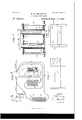
- Figure 1 is a side elevation, partly in section, of a lamp embodying my invention.
- Fig. 2 is a central vertical section on the lines 2-2 of Figs. 3 and 4.
- Fig. 3 is a side elevation of the lamp with its inclosing casing removed.
- Fig. 4 is a plan view of the same.
- Fig. 5 is a detail sectional view illustrating the construction of the shunt magnets.
- Fig. 6 is a detail View of a modified form of spool and armature for the main magnet.
- Fig. 7 is a detail view of another modified form of spool and armature of the main magnet; and
- Fig. 8 is a diagram of the lamp circuits.
- My invention may be used in connection with any ordinary frame and carbon holder, and as shown, it is provided with abed plate 10, supporting bridges or top plates 11, and posts 12 extending from the bed plate to the top plates, thus forming a frame to which the other mechanism may be secured.
- the mechanism carried on this frame is preferably inclosed in a case 13, to protect it from the weather.
- Extending vertically through the frame is a feed rod 14, which is of the usual kind, and in which the upper carbon of the lamp is held in the customary manner.
- a main magnet 15 which is arranged at one side of the feed rod, and preferably in a horizontal position, the magnet being mounted in suitable supports 16, and above it is aswinging armature 17 which is pivoted at one end, as shown at 18, and the movement of the free end of which is limited by a bent arm 18.
- This armature is provided with a depending arm 19 (see Fig. 1) which is flexibly connected by means of a spring 20, with a lever 22 operating the feed mechanism, the spring being adjustably connected with the said lever by means of a screw 21 in one end of the lever, and a suitable nut 23 on the screw. By means of this screw and nut, the tension of the spring may be very nicely adjusted.
- the lever 22 is arranged in a substantially horizontal position, and is provided with a rib 22 to give it the necessary strength and lightness, and also to facilitate its connection with other parts.
- the lever is provided near the center, at which point it is widened, with a large perforation 24, through which the feed rod 14 extends, and at opposite sides of the lever are depending ears 25, which are supported on screws 26 in the lamp frame, and which thus serve as a fulcrum for the lever.
- the lever is connected on the side of the feed rod opposite the main magnet, with a link 27, which extends downward nearly parallel with the feed rod, and is at its lower end pivoted to a clutch 28 of the usual kind, which embraces the feed rod and is supported at its opposite end on a screw 29, the point of which rests on the bed plate 10.
- the main magnet may be so wound that it will have a sufficient amount of magnetism to hold its armature and preserve its tension on the spring through a large change of current quantity.
- I may make a lamp for currents varying from six to ten ampres. Now,if Iwind my main magnet so that it will The v IOC attract its armature enough to pull it down and start a current of, say five amperes, it will obviously hold it there as long as the current is five amperes or more, up to the time when a sufficient amount of current should pass to destroy the insulation.
- the lamp After the lamp has picked up, or started to burn, through the action of the main magnet, it will continue to burn a constant length of are, even though the amperes of current should vary largely, so long as they do not become less than a predetermined value, or great enough to overheat the magnet.
- the shunt magnets are arranged to operate in connection with the lever 22 so as to balance in a measure the spring 20 and the pull of the main magnet so as to perfectly control the feed, the connection and operation being fully described below.
- the shunt magnets 33 are preferably constructed as shown in Fig. 5, to enable them to be easily placed in or removed from the lamp frame, and as here shown, each magnet is provided with a suitable hollow core 34:, forming the body of the spool, and with heads 35 which are arranged between the bed plate 10 and a cross bar 36 above and parallel with the bed plate, the cores 34 of the spools protruding through the heads 35 so as to enter the bed plate 10 and cross bar 36.
- the cross bar is held in place by screws 37 extending from the cross bar to the bed plate, and by removing the screws and raising the cross bar, the magnets may be removed or placed in position.
- a cut-out 38 (see Fig. 1) comprising a spring plate 39, which is provided with a shank 40 secured to the lamp frame, and a second contact plate ll which is secured to a support 42 above the plate 39, and these plates are normally separated, but will be drawn together when the voltage of the arc shall exceed a predetermined Value, and so short circuit the lamp and prevent it from being burned out.
- the cut-out is operated by the lever 22, the lower contact plate 39 being connected with the lever 22 on the side next the main magnet by means of a rod or screw 39 which extends downward through the plate 39, with its head below the plate,
- the resistance comprises two coils 43, which are secured to the support 4-2 and are connected together at the bottom, being fastened to a convenient support on the bed plate.
- the lamp is provided with the usual binding posts and lamp frame (which are not shown because they form no part of this invention) and the current comes in through the positive binding post 44:, (see Fig. 8,) passes through the carbons 46, the main magnet 15, and out through the negative binding post 45.
- the shunt magnets 33 which are connected with the carloons as the diagram shows, and the shunt magnets tilt the lever 22 against the tension of the spring 20, thus permitting the feed rod to drop slightly and hold the arc at normal length, the main magnet operating as already described to lift the feed rod and the shunt magnets to drop it, and thus the two magnets balance each other and preserve the length of the are.
- the magnet in the first case being provided with a spool 47, the core of which has a projecting end 48 which is concaved on one side, as shown at a9, while opposite this concaved end is arranged an armature 50, having a convex side next the concavity of the core, this arrangement being intended to produce a gradual pull on the armature and avoid any abrupt action.
- a spool 47 the core of which has a projecting end 48 which is concaved on one side, as shown at a9
- an armature 50 having a convex side next the concavity of the core
- Figs. 6 and 7 may also be substituted for the solenoids in the shunt circuit, if desired.
Landscapes
- Engineering & Computer Science (AREA)
- Physics & Mathematics (AREA)
- Plasma & Fusion (AREA)
- Mechanical Engineering (AREA)
- Lighting Device Outwards From Vehicle And Optical Signal (AREA)
Description
(No Model.) 3 Sheets-Sheet 1. H. E. BRADLEY.
ELECTRIC ARC LAMP.
Patented Sept. 11, 1894.
IN VEN 70/? W59,
WITNESSES.
A TTOHNE Y8.
0., wnsummou n c 3 v E L D A R B B H ELECTRIC ARC LAMP.
No. 625,943. Pa ented Sept. 11,1894
W/TNE A TTOHNE VS.
(No Model.) 3 SheetsSheet 3. H. E. BRADLEY.
ELECTRIC ARC LAMP.
A TTOHNE YS,
lNVENTO/a W .552 w Patented Sept. 11, 1894.
m: NORRIS PETERS co, pnmuuma, WASHINGTON, n c
W/TNESSES: fig/5'5 UNITED STATES PATENT OFFIC HAROLD E. BRADLEY, OF NEW BEDFORD, MASSACHUSETTS.
ELECTRIC-ARC LAM P.
SPECIFICATION forming part of Letters I'ate nt No. 525,943, dated September 11, 1894:.
Application filed February 28, 1894. 'Serial No. 501,840. (N 0 model.)
To all whom it may concern.-
Be it known that I, HAROLD E. BRADLEY, of New Bedford, in the county of Bristol and State of Massachusetts, have invented a new and Improved Electric-Arc Lamp, of which the following is a full, clear, and exact description.
My invention relates to improvements in arc lamps, and the object of my invention is to simplify and cheapen lamps of this class; also to improve the feed mechanism so that the feed shall be extremely regular, to provide a resistance and cut-out which will work automatically to short circuit the lamp if the current becomes too strong and so prevent the burning out of the lamp, and in general, to make a lamp which is durable, easily placed in position, and capable of giving a steady light.
To these ends, my invention consists of certain features of construction and combinations of parts, which will be hereinafter described and then pointed out in the claim.
Reference is to be had to the accompanying drawings, forming a part of this specification, in which similar figures of reference indicate corresponding parts in all the views.
Figure 1 is a side elevation, partly in section, of a lamp embodying my invention. Fig. 2 is a central vertical section on the lines 2-2 of Figs. 3 and 4. Fig. 3 is a side elevation of the lamp with its inclosing casing removed. Fig. 4 is a plan view of the same. Fig. 5 is a detail sectional view illustrating the construction of the shunt magnets. Fig. 6 is a detail View of a modified form of spool and armature for the main magnet. Fig. 7 is a detail view of another modified form of spool and armature of the main magnet; and Fig. 8 is a diagram of the lamp circuits.
My invention may be used in connection with any ordinary frame and carbon holder, and as shown, it is provided with abed plate 10, supporting bridges or top plates 11, and posts 12 extending from the bed plate to the top plates, thus forming a frame to which the other mechanism may be secured. The mechanism carried on this frame is preferably inclosed in a case 13, to protect it from the weather. Extending vertically through the frame is a feed rod 14, which is of the usual kind, and in which the upper carbon of the lamp is held in the customary manner. current as it enters the lamp passes through a main magnet 15, which is arranged at one side of the feed rod, and preferably in a horizontal position, the magnet being mounted in suitable supports 16, and above it is aswinging armature 17 which is pivoted at one end, as shown at 18, and the movement of the free end of which is limited by a bent arm 18. This armature is provided with a depending arm 19 (see Fig. 1) which is flexibly connected by means of a spring 20, with a lever 22 operating the feed mechanism, the spring being adjustably connected with the said lever by means of a screw 21 in one end of the lever, and a suitable nut 23 on the screw. By means of this screw and nut, the tension of the spring may be very nicely adjusted.
The lever 22 is arranged in a substantially horizontal position, and is provided with a rib 22 to give it the necessary strength and lightness, and also to facilitate its connection with other parts. The lever is provided near the center, at which point it is widened, with a large perforation 24, through which the feed rod 14 extends, and at opposite sides of the lever are depending ears 25, which are supported on screws 26 in the lamp frame, and which thus serve as a fulcrum for the lever. The lever is connected on the side of the feed rod opposite the main magnet, with a link 27, which extends downward nearly parallel with the feed rod, and is at its lower end pivoted to a clutch 28 of the usual kind, which embraces the feed rod and is supported at its opposite end on a screw 29, the point of which rests on the bed plate 10. It will thus be seen that when the current passes through the main magnet, the magnet being energized, draws down the armature 17, which acting on the arm 19 and spring 20, depresses the lever 22, thus lifting the end on the opposite side of the feed rod, and raising the link 27 and clutch 28, which lifts the feed rod and the upper carbon, thus starting the arc.
The main magnet may be so wound that it will have a sufficient amount of magnetism to hold its armature and preserve its tension on the spring through a large change of current quantity. Thus I may make a lamp for currents varying from six to ten ampres. Now,if Iwind my main magnet so that it will The v IOC attract its armature enough to pull it down and start a current of, say five amperes, it will obviously hold it there as long as the current is five amperes or more, up to the time when a sufficient amount of current should pass to destroy the insulation. After the lamp has picked up, or started to burn, through the action of the main magnet, it will continue to burn a constant length of are, even though the amperes of current should vary largely, so long as they do not become less than a predetermined value, or great enough to overheat the magnet.
One end of the lever 22, the end on the side of the lamp opposite the main magnet, is connected by means of a link 30 with the yoke 31 of the plungers 32 of the solenoid shunt magnets 33, this form of magnet being preferably employed, although other kinds of magnets may be used if desired. The shunt magnets are arranged to operate in connection with the lever 22 so as to balance in a measure the spring 20 and the pull of the main magnet so as to perfectly control the feed, the connection and operation being fully described below.
The shunt magnets 33 are preferably constructed as shown in Fig. 5, to enable them to be easily placed in or removed from the lamp frame, and as here shown, each magnet is provided with a suitable hollow core 34:, forming the body of the spool, and with heads 35 which are arranged between the bed plate 10 and a cross bar 36 above and parallel with the bed plate, the cores 34 of the spools protruding through the heads 35 so as to enter the bed plate 10 and cross bar 36. The cross bar is held in place by screws 37 extending from the cross bar to the bed plate, and by removing the screws and raising the cross bar, the magnets may be removed or placed in position.
In connection with the feed mechanism, I have provided a cut-out 38 (see Fig. 1) comprising a spring plate 39, which is provided with a shank 40 secured to the lamp frame, and a second contact plate ll which is secured to a support 42 above the plate 39, and these plates are normally separated, but will be drawn together when the voltage of the arc shall exceed a predetermined Value, and so short circuit the lamp and prevent it from being burned out. The cut-out is operated by the lever 22, the lower contact plate 39 being connected with the lever 22 on the side next the main magnet by means of a rod or screw 39 which extends downward through the plate 39, with its head below the plate,
and when the lever 22 is tilted by the action of the shunt magnets, to a great extent, the screw 39 lifts the plate 39 and brings it against the plate 41, thus short circuiting the lamp, as will appear from the description of the circuits to be described below.
In connection with the cut-out I have provided a resistance which will be included in the circuit when the cut-out acts, the object of this being to throw a sufficientamount of current through the main magnet to start the arc in case the carbons should again come in contact. The resistance comprises two coils 43, which are secured to the support 4-2 and are connected together at the bottom, being fastened to a convenient support on the bed plate.
The lamp is provided with the usual binding posts and lamp frame (which are not shown because they form no part of this invention) and the current comes in through the positive binding post 44:, (see Fig. 8,) passes through the carbons 46, the main magnet 15, and out through the negative binding post 45. As the arc increases in length, a portion of the current passes through the shunt magnets 33, which are connected with the carloons as the diagram shows, and the shunt magnets tilt the lever 22 against the tension of the spring 20, thus permitting the feed rod to drop slightly and hold the arc at normal length, the main magnet operating as already described to lift the feed rod and the shunt magnets to drop it, and thus the two magnets balance each other and preserve the length of the are. If the feed rod should descend so far as to materially reduce the dilference of potential existing around the are, then the pull of the shunt magnets on their cores will be decreased to a su'fficient extent to allow the spring 20 to raise the feed rod through the agency of the lever 22, link 27 and clutch 28. The upper plate 4E1 of the cut-outis connected with the positive binding post, and the lower plate 39 is connected through the resistance coils 3 with the negative binding post, as the diagram shows. If the end of the lever 22 next the shunt magnets is depressed to too great an extent, the lower plate 39 of the cutout is raised into contact with the plate 41, and the lamp is thus short circuited, the current passing through the cut-out plates and the resistance coils 43, as per diagram, but if the carbons again come in contact, the resist ance causes sufficient current to pass through the main magnet to energize it and again raise the feed rod so as to start the arc.
Instead of constructing the main magnet as shown, it may be made as illustrated in either Fig. 7 or Fig. 6, the magnet in the first case being provided with a spool 47, the core of which has a projecting end 48 which is concaved on one side, as shown at a9, while opposite this concaved end is arranged an armature 50, having a convex side next the concavity of the core, this arrangement being intended to produce a gradual pull on the armature and avoid any abrupt action. The same effect is had by arranging the pole pieces of the magnet and the armature as illustrated in Fig. 6, in which case the spool 51 has its heads 52 beveled at one edge, as shown at 53, while the armature 54 has bent ends 55, the incline of which corresponds to the bevel 53, so that the action on the armature is thus rendered gradual and positive, a
comparatively large surface of the armature being exposed to magnetic action. The forms of magnets shown in Figs. 6 and 7 may also be substituted for the solenoids in the shunt circuit, if desired.
In the foregoing description and in the drawings, I have described and shown a feed rod operated by a clutch, but it will be understoodthat if the feed rod is provided with a rack, the tilting lever 22 may be geared to the rack so as to operate substantially as described. A
Having thus described my invention, I claim as new and desire to secure by Letters Patentplate, substantially as and for the purpose set forth.
HAROLD E. BRADLEY.
Witnesses:
BENJ. B. BARNEY, E. L. BARNEY, Jr.
Publications (1)
| Publication Number | Publication Date |
|---|---|
| US525943A true US525943A (en) | 1894-09-11 |
Family
ID=2594733
Family Applications (1)
| Application Number | Title | Priority Date | Filing Date |
|---|---|---|---|
| US525943D Expired - Lifetime US525943A (en) | Electric-arc lamp |
Country Status (1)
| Country | Link |
|---|---|
| US (1) | US525943A (en) |
-
0
- US US525943D patent/US525943A/en not_active Expired - Lifetime
Similar Documents
| Publication | Publication Date | Title |
|---|---|---|
| US525943A (en) | Electric-arc lamp | |
| US582664A (en) | Electric-arc lamp | |
| US306517A (en) | Electric-arc lamp | |
| US365553A (en) | Electric-arc lamp | |
| US448418A (en) | And william d | |
| US301550A (en) | Electric arc lamp | |
| US537617A (en) | Charles a | |
| US559648A (en) | Andrew b | |
| US667121A (en) | Electric-arc lamp. | |
| US374129A (en) | Arc light | |
| US539877A (en) | Electric-arc lamp | |
| US693705A (en) | Electric-arc lamp. | |
| USRE11002E (en) | Electric-arc lamp | |
| US348542A (en) | Electric-arc lamp | |
| US524116A (en) | Electric-arc lamp | |
| US268254A (en) | Electric-arc lamp | |
| US560421A (en) | James mclaughlin | |
| US404351A (en) | Electric-arc lamp | |
| US667122A (en) | Electric-arc lamp. | |
| US1055361A (en) | Arc-lamp. | |
| US664713A (en) | Electric-arc lamp. | |
| US560039A (en) | Electric-arc lamp | |
| US434175A (en) | Electric-arc lamp | |
| US559649A (en) | wheless | |
| US269151A (en) | Electric-arc lamp |