US525938A - Churn - Google Patents
Churn Download PDFInfo
- Publication number
- US525938A US525938A US525938DA US525938A US 525938 A US525938 A US 525938A US 525938D A US525938D A US 525938DA US 525938 A US525938 A US 525938A
- Authority
- US
- United States
- Prior art keywords
- shaft
- dasher
- churn
- arms
- sleeve
- Prior art date
- Legal status (The legal status is an assumption and is not a legal conclusion. Google has not performed a legal analysis and makes no representation as to the accuracy of the status listed.)
- Expired - Lifetime
Links
- 239000006071 cream Substances 0.000 description 4
- 235000019738 Limestone Nutrition 0.000 description 1
- 238000010276 construction Methods 0.000 description 1
- 230000009191 jumping Effects 0.000 description 1
- 239000006028 limestone Substances 0.000 description 1
- 230000000284 resting effect Effects 0.000 description 1
Images
Classifications
-
- B—PERFORMING OPERATIONS; TRANSPORTING
- B01—PHYSICAL OR CHEMICAL PROCESSES OR APPARATUS IN GENERAL
- B01F—MIXING, e.g. DISSOLVING, EMULSIFYING OR DISPERSING
- B01F27/00—Mixers with rotary stirring devices in fixed receptacles; Kneaders
- B01F27/80—Mixers with rotary stirring devices in fixed receptacles; Kneaders with stirrers rotating about a substantially vertical axis
- B01F27/81—Mixers with rotary stirring devices in fixed receptacles; Kneaders with stirrers rotating about a substantially vertical axis the stirrers having central axial inflow and substantially radial outflow
Definitions
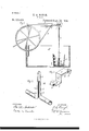
- Figure 1 of the drawings is a representation of a side elevation of the invention partly in section.
- Fig. 2 is a perspective view of the dasher.
- Fig. 3 is a detail of bracket and bolt.
- This invention has relation to certain new and usefulimprovementsin a combined churn motor and dasher, my object being to provide a simple and eifective, and inexpensive device of this character; and the invention consists in the novel construction and combination of parts, all as hereinafter described and pointed out in the appended claims.
- the letter A designates a suitable frame for supporting the motor, and which may, as indicated, form a cage or receptacle for a churn B.
- a motor or power wheel O J ournaled on an upright of said frame is a motor or power wheel O, designed to be rotated by a crank, or other suitable power, and having a grooved periphery for a belt or band D.
- Extending horizontally over the frame from said upright is an arm E, which, at its extremity has formed therein an elongated horizontal slot a.
- F is a bracket which is attached to said arm by means of abolt G which passes through the slot a, being held by a nut or tap b, which, upon being loosened, p'tirmits the bracket to wheel.
- H designates the vertical dasher shaft which at its lower end is removably stepped in a bearing 0 in or on the churn bottom, and at its upper end has a half-bearing d, in a horizontal, projecting arm f of the bracket F.
- I is a small recessed guard block which is secured to the armfover the upper end of the said dasher shaft, and serves to keep the latter from jumping out of its lower bearing, while permitting it to be readily removed from its bearings by a lateral and vertical movement.
- J is a pulley on the shaft H which is on a line with the top portion of the power wheel.
- K is an idler journaled on a depending arm, and over which is passed the lower portion of the belt or band.
- This idler is also in the line of the shaft pulley or power wheel, this arrangement makingit possible to run the upright shaft with the upright power wheel.
- M designates the dasher, which consists of a pair of short, opposite tubular arms L, open at both ends, the openings of the inner ends of the arms being upon opposite sides of the shaft.
- Said arms are carried by a sleeve-like pieceN open at one side, and having the edges thereof bent outwardly, forming flangesm m.
- Said sleeve is made to fit the shaft closely but removably, and is usually secured thereon by means of a spring loop P which engages notches or catches p on the shaft, a series of such notches or catches being usually provided at different heights in order that the dasher arms may be adjusted to suit the quantity of cream in the churn.
- This form of dasher is found to be very effective in that a continual circulation of the cream is kept up through the tubular arms L, aided by the flanges m m, which form abutments to the cream, and not only agitate it but direct it into the said arms. This circulation is maintained by suction, the cream being drawn down around the shaft, and thrown outwardly through the tubular arms.
- R designates a circular disk placed around and resting upon, or slightly above, the dasher arms for the purpose of preventing splashing.
- the rotary dashershaft having the sleeve on its lower portion, the opposite tubular arms L carried by said sleeve, said arms being open at both ends, the inner openings being upon opposite sides of the shaft, said sleeve having the flanges m, m,
- a churn dasher the combination with a rotary dasher shaft, having a series of notches or catches thereon at difierent heights, of the sleeve on the lower portion of said shaft said sleeve having the flanges m, m, and the tubular arms L, the spring loop carried by said sleeve and adapted to engage any one of said notches or catches, substantially as specified.
Landscapes
- Chemical & Material Sciences (AREA)
- Chemical Kinetics & Catalysis (AREA)
- Devices For Conveying Motion By Means Of Endless Flexible Members (AREA)
Description
E. H. BAU'GH.
(No Model.)
GHURN.
Patented Sept. 11, 1894.
' d%IJ/%ZZOR I be adjusted toward and away from the power UNITED STATES EDWARD H. BAUGH,
PATENT OFFICE.
OF MEXIA, TEXAS.
CHURN.
SPECIFICATION forming part of Letters Patent No. 525,938, dated September 11, 1894.
Application filed May 29, 1894:- Serial No. 512,831. (No model.)
To aZZ whom it may concern.-
Be it known that I, EDWARD H. BAUGH, a citizen of the United States, and a resident of Mexia, in the county of Limestone and State of Texas, have invented certain new and useful Improvements in Churn Motors and Dashers; and I do declare the following to be a f ull, clear, and exact description of the inventron, such as will enable others skilled in the art to which it appertains to make and use the same, reference being had to the accompanying drawings, and to letters of reference marked thereon, which form a part of this specification.
Figure 1 of the drawings is a representation of a side elevation of the invention partly in section. Fig. 2 is a perspective view of the dasher. Fig. 3 is a detail of bracket and bolt.
This invention has relation to certain new and usefulimprovementsin a combined churn motor and dasher, my object being to provide a simple and eifective, and inexpensive device of this character; and the invention consists in the novel construction and combination of parts, all as hereinafter described and pointed out in the appended claims.
Referring to .the accompanying drawings the letter A designates a suitable frame for supporting the motor, and which may, as indicated, form a cage or receptacle for a churn B. J ournaled on an upright of said frame is a motor or power wheel O, designed to be rotated by a crank, or other suitable power, and having a grooved periphery for a belt or band D. Extending horizontally over the frame from said upright is an arm E, which, at its extremity has formed therein an elongated horizontal slot a.
F is a bracket which is attached to said arm by means of abolt G which passes through the slot a, being held by a nut or tap b, which, upon being loosened, p'tirmits the bracket to wheel.
H designates the vertical dasher shaft which at its lower end is removably stepped in a bearing 0 in or on the churn bottom, and at its upper end has a half-bearing d, in a horizontal, projecting arm f of the bracket F. I is a small recessed guard block which is secured to the armfover the upper end of the said dasher shaft, and serves to keep the latter from jumping out of its lower bearing, while permitting it to be readily removed from its bearings by a lateral and vertical movement.
J is a pulley on the shaft H which is on a line with the top portion of the power wheel.
K is an idler journaled on a depending arm, and over which is passed the lower portion of the belt or band. This idler is also in the line of the shaft pulley or power wheel, this arrangement makingit possible to run the upright shaft with the upright power wheel.
M designates the dasher, which consists of a pair of short, opposite tubular arms L, open at both ends, the openings of the inner ends of the arms being upon opposite sides of the shaft. Said arms are carried by a sleeve-like pieceN open at one side, and having the edges thereof bent outwardly, forming flangesm m. Said sleeve is made to fit the shaft closely but removably, and is usually secured thereon by means of a spring loop P which engages notches or catches p on the shaft, a series of such notches or catches being usually provided at different heights in order that the dasher arms may be adjusted to suit the quantity of cream in the churn.
This form of dasher is found to be very effective in that a continual circulation of the cream is kept up through the tubular arms L, aided by the flanges m m, which form abutments to the cream, and not only agitate it but direct it into the said arms. This circulation is maintained by suction, the cream being drawn down around the shaft, and thrown outwardly through the tubular arms.
R designates a circular disk placed around and resting upon, or slightly above, the dasher arms for the purpose of preventing splashing.
Having described my invention, what I claim as new, and desire to secure by Letters Patent, is-
1. In a churn 'motor or dasher, the combination of the upright, the arm E, the bracket F adj ustably carried by said upright, the dasher shaft removably stepped in a bearing in the churn, and having a half-bearing in said bracket, the guard block on said bracket, the pulley on said shaft, the idler carried by an arm of said arm E, the power wheel journaled on said upright, and the driving belt or band, said shaft, pulley and idler being in line with the upper portion of said power wheel, substantially as specified.
2. In aehnrn dasher, the rotary dashershaft having the sleeve on its lower portion, the opposite tubular arms L carried by said sleeve, said arms being open at both ends, the inner openings being upon opposite sides of the shaft, said sleeve having the flanges m, m,
substantially as specified.
3. In a churn dasher, the combination with a rotary dasher shaft, having a series of notches or catches thereon at difierent heights, of the sleeve on the lower portion of said shaft said sleeve having the flanges m, m, and the tubular arms L, the spring loop carried by said sleeve and adapted to engage any one of said notches or catches, substantially as specified.
4. In a churn dasher, the combination with a rotary dasher shaft, of a sleeve on the lower portion of said shaft, and having the oppono site, tubular arms, said arms being open at both ends, and the flanges m, m and the guard R carried by said shaft, substantial] y as specifled.
In testimony whereof I affix my signature in :5
Publications (1)
| Publication Number | Publication Date |
|---|---|
| US525938A true US525938A (en) | 1894-09-11 |
Family
ID=2594728
Family Applications (1)
| Application Number | Title | Priority Date | Filing Date |
|---|---|---|---|
| US525938D Expired - Lifetime US525938A (en) | Churn |
Country Status (1)
| Country | Link |
|---|---|
| US (1) | US525938A (en) |
-
0
- US US525938D patent/US525938A/en not_active Expired - Lifetime
Similar Documents
| Publication | Publication Date | Title |
|---|---|---|
| US525938A (en) | Churn | |
| US496674A (en) | John theodore urbach | |
| US401306A (en) | Paint-mixer | |
| US192838A (en) | Improvement in churns | |
| US1056778A (en) | Churn. | |
| US670469A (en) | Churn. | |
| US716566A (en) | Churn. | |
| US567018A (en) | Churn | |
| US297918A (en) | Churn | |
| US582095A (en) | Churn | |
| US943580A (en) | Churn-motor. | |
| US328457A (en) | Egg-beater | |
| US302794A (en) | Elbbrt c | |
| US224493A (en) | Churn | |
| US630843A (en) | Glass or bottle washer. | |
| US573400A (en) | Churn | |
| US631171A (en) | Churn. | |
| US164034A (en) | Improvement in reciprocating churns | |
| US500160A (en) | And william d | |
| US326936A (en) | Churn | |
| US334522A (en) | Churn-motor | |
| US844464A (en) | Butter-churn. | |
| US626623A (en) | Churn | |
| US576440A (en) | Churn | |
| US333358A (en) | Churn |