US5259156A - Grinding method and clamping device - Google Patents
Grinding method and clamping device Download PDFInfo
- Publication number
- US5259156A US5259156A US07/876,705 US87670592A US5259156A US 5259156 A US5259156 A US 5259156A US 87670592 A US87670592 A US 87670592A US 5259156 A US5259156 A US 5259156A
- Authority
- US
- United States
- Prior art keywords
- workpiece
- ring
- bore
- grinding
- internal
- Prior art date
- Legal status (The legal status is an assumption and is not a legal conclusion. Google has not performed a legal analysis and makes no representation as to the accuracy of the status listed.)
- Expired - Lifetime
Links
Images

Classifications
-
- B—PERFORMING OPERATIONS; TRANSPORTING
- B24—GRINDING; POLISHING
- B24B—MACHINES, DEVICES, OR PROCESSES FOR GRINDING OR POLISHING; DRESSING OR CONDITIONING OF ABRADING SURFACES; FEEDING OF GRINDING, POLISHING, OR LAPPING AGENTS
- B24B41/00—Component parts such as frames, beds, carriages, headstocks
- B24B41/06—Work supports, e.g. adjustable steadies
- B24B41/061—Work supports, e.g. adjustable steadies axially supporting turning workpieces, e.g. magnetically, pneumatically
-
- Y—GENERAL TAGGING OF NEW TECHNOLOGICAL DEVELOPMENTS; GENERAL TAGGING OF CROSS-SECTIONAL TECHNOLOGIES SPANNING OVER SEVERAL SECTIONS OF THE IPC; TECHNICAL SUBJECTS COVERED BY FORMER USPC CROSS-REFERENCE ART COLLECTIONS [XRACs] AND DIGESTS
- Y10—TECHNICAL SUBJECTS COVERED BY FORMER USPC
- Y10T—TECHNICAL SUBJECTS COVERED BY FORMER US CLASSIFICATION
- Y10T82/00—Turning
- Y10T82/25—Lathe
- Y10T82/2568—Center
Definitions
- the present invention relates to an auxiliary member for use in connection with grinding machinery and more particularly for grinding the internal bore, i.e. the lumen of hollow workpieces which are also of external circular cross-section.
- the system and device according to the invention is a new concept of clamping, driving and grinding for internal grinding machines where the system makes it possible to clamp and drive the workpiece on an internal grinding machine between two dead centers on the workpiece's axis as is known and used in outside grinding operations or other machining processes.
- the advantage of employing the new auxiliary device resides therein, that it permits the use of the same base and data point for the two grinding operations and as a consequence to attain precision and coincidence of the central axes of the two circles ascribing the outer periphery and that of the lumen of the workpiece.
- a further advantage of the use of the auxiliary device is the fact that an operator is free to attend to the external surface of the workpiece first and then to the internal wall of the bore, or vice versa.
- the new system is based on "hollow conical center ring" which is used to clamp the workpiece on one end or side and a dead center on the other end or side of the workpiece with different driving rings or fingers to drive the workpiece.
- the "hollow conical center ring” which is mounted in a steady rest on the internal grinding machine table, aligned and centered with the machine workpiece driving center, clamps the workpiece by using the internal bore to be ground as a center point, while still making it possible to perform internal grinding on the inner diameter through the "hollow conical center ring".
- a recess should be ground on the cone of the "hollow conical center ring” with the internal grinding wheel for which the diameter is never more than two thirds of the workpiece bore to be ground, leaving at least two thirds of the cone of the "hollow conical center ring" for the workpiece clamping and making it possible to clamp the workpiece with enough rigidity to perform the necessary precision grinding operation.
- This system is applicable to most of the existing internal grinding machines by simple adaptors and it also can be used in light and precision bore turning operations on the lathes and other machines.
- the new device consists of an at least partly exteriorily conical ring having an external circumferentially extending flange or ridge, such that the axial cross section of the said conical portion is that of a frustum of a cone.
- the internal wall of the ring also ascribes a frustum of a cone.
- a recess is provided on the internal wall of the new ring device extending up to about one third of the circumference of the circular internal wall of the device (i.e. up to about 120°).
- the extension of the arcuate recess will be about 30°, the said recess serving to facilitate the introduction of a grinding wheel into the internal space of the device.
- the ring which rests on a steadying support is introduced with the smaller circumferential edge of the frustum into the lumen of the workpiece whose opposite end is turnably held by a dead-center of the machine and is in driving contact with an appropriately driving ring and finger.
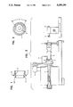
- FIG. 1 is an axial sectional view of the new device.
- FIG. 2- an end-view thereof, indicating also a grinding wheel within the confines of the inside lumen of the workpiece.
- FIG. 3 is a schematic view of a lathe-like grinding machine, with the new device in operational position thereon.
- FIG. 4 is a perspective view of a device of the invention.
- FIG. 5 is a cross-sectional view of the device of FIG. 4.
- the machine comprises in a conventional manner, a chucking cylinder 1, which includes a shaft 1', terminating in dead center 2. There is provided a transmission gear 7 and a driving mechanism 6 for imparting rotational movement to a workpiece 8. The necessary drive is provided by an electric motor 9. All these parts and their function is known and requires no further detailed description.
- the new device shown in FIGS. 1 and 2 consists of a partly frustoconically shaped ring 4 which is surrounded by a circumferential ridge 4' positioned intermediate the two end edges of the ring.
- the frusto-conical portion marked 4" of ring 4 extends on the forward part of the ring and is delimited by the ridge 4'.
- the smaller peripheral end edge of the frusto-conical portion 4" of ring 4 enters the circular lumen of the workpiece, the ring being safely supported on a steadying support 3.
- the grinding wheel 5 fixed on a spindle 5' and driven in a generally known way is carried with its drive on a hydraulical table and can be brought to enter the interior of the workpiece to be ground, traversing the inner space of ring 4.
- a portion of the internal wall of the auxiliary member is recessed by grinding (or otherwise) an arcurate recess extending along not more than about a third (120°) of the inner circular wall of the auxiliary member; the said recess indicated by the letter R in FIG. 2 will in practice extend over an arc of about 30°.
- FIG. 4 illustrates the new device, in perspective
- FIG. 5 shows a section therethrough, particularly emphasizing recess R, also shown in FIG. 2.
- recess R facilitates entry of grinding wheel 5 into the interior of the workpiece to be ground.
- Grinding wheel 5 passes through ring 4 to grind the workpiece through recess R in frusto-conical portion 4", the edge of which is entered into the circular lumen of the workpiece.
- the auxiliary member 10 (which is the new device) rests in stationary position in support 3 with end 4" entered into workpiece 8.
- the workpiece 8 is rotated while its interior surface is ground using grinding wheel 5.
Landscapes
- Engineering & Computer Science (AREA)
- Mechanical Engineering (AREA)
- Grinding Of Cylindrical And Plane Surfaces (AREA)
Abstract
Description
Claims (7)
Priority Applications (1)
| Application Number | Priority Date | Filing Date | Title |
|---|---|---|---|
| US07/876,705 US5259156A (en) | 1990-02-23 | 1992-04-29 | Grinding method and clamping device |
Applications Claiming Priority (4)
| Application Number | Priority Date | Filing Date | Title |
|---|---|---|---|
| IL93515A IL93515A0 (en) | 1990-02-23 | 1990-02-23 | Grinding machine accessory |
| IL93515 | 1990-02-23 | ||
| US60152790A | 1990-10-23 | 1990-10-23 | |
| US07/876,705 US5259156A (en) | 1990-02-23 | 1992-04-29 | Grinding method and clamping device |
Related Parent Applications (1)
| Application Number | Title | Priority Date | Filing Date |
|---|---|---|---|
| US60152790A Continuation-In-Part | 1990-02-23 | 1990-10-23 |
Publications (1)
| Publication Number | Publication Date |
|---|---|
| US5259156A true US5259156A (en) | 1993-11-09 |
Family
ID=27271432
Family Applications (1)
| Application Number | Title | Priority Date | Filing Date |
|---|---|---|---|
| US07/876,705 Expired - Lifetime US5259156A (en) | 1990-02-23 | 1992-04-29 | Grinding method and clamping device |
Country Status (1)
| Country | Link |
|---|---|
| US (1) | US5259156A (en) |
Cited By (9)
| Publication number | Priority date | Publication date | Assignee | Title |
|---|---|---|---|---|
| US5531633A (en) * | 1994-03-24 | 1996-07-02 | Ingersoll-Rand Company | Method of machining a metal workpiece |
| US5752706A (en) * | 1996-07-18 | 1998-05-19 | Hodges; Lyndon W. | Adjustable tool holder for machine tools |
| WO1998057778A1 (en) * | 1997-06-16 | 1998-12-23 | Constant Velocity Systems, Inc. | Inner race grinding machine |
| US5893793A (en) * | 1996-10-02 | 1999-04-13 | Ngk Insulators, Ltd. | Process and apparatus for chucking and machining an elongated cylindrical article made of a ceramic material |
| US6241590B1 (en) * | 1997-07-04 | 2001-06-05 | Lidkoping Machine Tools Ab | External abrasive machine |
| US6322423B1 (en) | 1997-07-04 | 2001-11-27 | Lidkoping Machine Tools Ab | Internal abrasive machine |
| US20080102736A1 (en) * | 2004-09-08 | 2008-05-01 | Peter Reim | Method For Machining Rotary Parts |
| CN101954608A (en) * | 2010-09-25 | 2011-01-26 | 北京星航机电设备厂 | Planer fixture for machining gap pouring gates and other tapered parts |
| CN107635720A (en) * | 2015-06-17 | 2018-01-26 | 埃尔温容克尔机械制造有限公司 | For being ground the outline of workpiece and the method and grinding machine of Internal periphery under clamp position |
Citations (12)
| Publication number | Priority date | Publication date | Assignee | Title |
|---|---|---|---|---|
| US811684A (en) * | 1905-03-11 | 1906-02-06 | Phineas H Adams | Boring-machine. |
| US2011091A (en) * | 1934-03-13 | 1935-08-13 | Steinbauer Raymond Albert | Apparatus for grinding long cylinders |
| GB534102A (en) * | 1939-12-16 | 1941-02-27 | Alexander Dore | Improvements in or relating to lathe and like centres |
| US2390888A (en) * | 1943-11-01 | 1945-12-11 | Walter F Liber | Steady rest for lathes |
| US2816301A (en) * | 1955-04-13 | 1957-12-17 | Landis Machine Co | Work supporting, gripping and centering device |
| US2889668A (en) * | 1955-04-07 | 1959-06-09 | Ulvsunda Verkst Er Aktiebolag | Work holders of the centerless type for grinding machines |
| US2927406A (en) * | 1957-07-09 | 1960-03-08 | Bryant Grinder Corp | Work loading and supporting device for an internal grinding machine |
| US3136102A (en) * | 1960-06-02 | 1964-06-09 | Messerschmidt Sebastian | Apparatus for chucking cylindrical workpieces on grinding machines |
| US3403482A (en) * | 1966-02-25 | 1968-10-01 | Trw Inc | Adapter apparatus for resizing pistons |
| US3557492A (en) * | 1969-06-25 | 1971-01-26 | Barnes Drill Co | Clamping fixture for a machine tool |
| US3754747A (en) * | 1970-12-25 | 1973-08-28 | Toyo Bearing Mfg Co | Apparatus for widthwise clamping workpieces in machine tools and the like |
| SU837564A1 (en) * | 1972-03-13 | 1981-06-15 | Минский тракторный завод | Back center |
-
1992
- 1992-04-29 US US07/876,705 patent/US5259156A/en not_active Expired - Lifetime
Patent Citations (12)
| Publication number | Priority date | Publication date | Assignee | Title |
|---|---|---|---|---|
| US811684A (en) * | 1905-03-11 | 1906-02-06 | Phineas H Adams | Boring-machine. |
| US2011091A (en) * | 1934-03-13 | 1935-08-13 | Steinbauer Raymond Albert | Apparatus for grinding long cylinders |
| GB534102A (en) * | 1939-12-16 | 1941-02-27 | Alexander Dore | Improvements in or relating to lathe and like centres |
| US2390888A (en) * | 1943-11-01 | 1945-12-11 | Walter F Liber | Steady rest for lathes |
| US2889668A (en) * | 1955-04-07 | 1959-06-09 | Ulvsunda Verkst Er Aktiebolag | Work holders of the centerless type for grinding machines |
| US2816301A (en) * | 1955-04-13 | 1957-12-17 | Landis Machine Co | Work supporting, gripping and centering device |
| US2927406A (en) * | 1957-07-09 | 1960-03-08 | Bryant Grinder Corp | Work loading and supporting device for an internal grinding machine |
| US3136102A (en) * | 1960-06-02 | 1964-06-09 | Messerschmidt Sebastian | Apparatus for chucking cylindrical workpieces on grinding machines |
| US3403482A (en) * | 1966-02-25 | 1968-10-01 | Trw Inc | Adapter apparatus for resizing pistons |
| US3557492A (en) * | 1969-06-25 | 1971-01-26 | Barnes Drill Co | Clamping fixture for a machine tool |
| US3754747A (en) * | 1970-12-25 | 1973-08-28 | Toyo Bearing Mfg Co | Apparatus for widthwise clamping workpieces in machine tools and the like |
| SU837564A1 (en) * | 1972-03-13 | 1981-06-15 | Минский тракторный завод | Back center |
Cited By (13)
| Publication number | Priority date | Publication date | Assignee | Title |
|---|---|---|---|---|
| US5531633A (en) * | 1994-03-24 | 1996-07-02 | Ingersoll-Rand Company | Method of machining a metal workpiece |
| US5916013A (en) * | 1996-01-29 | 1999-06-29 | Constant Velocity Systems, Inc. | Inner race grinding machine |
| US5752706A (en) * | 1996-07-18 | 1998-05-19 | Hodges; Lyndon W. | Adjustable tool holder for machine tools |
| US5893793A (en) * | 1996-10-02 | 1999-04-13 | Ngk Insulators, Ltd. | Process and apparatus for chucking and machining an elongated cylindrical article made of a ceramic material |
| WO1998057778A1 (en) * | 1997-06-16 | 1998-12-23 | Constant Velocity Systems, Inc. | Inner race grinding machine |
| US6322423B1 (en) | 1997-07-04 | 2001-11-27 | Lidkoping Machine Tools Ab | Internal abrasive machine |
| US6241590B1 (en) * | 1997-07-04 | 2001-06-05 | Lidkoping Machine Tools Ab | External abrasive machine |
| US20080102736A1 (en) * | 2004-09-08 | 2008-05-01 | Peter Reim | Method For Machining Rotary Parts |
| US7507147B2 (en) * | 2004-09-08 | 2009-03-24 | Erwin Junker Maschinenfabrik Gmbh | Method for machining rotary parts |
| CN101954608A (en) * | 2010-09-25 | 2011-01-26 | 北京星航机电设备厂 | Planer fixture for machining gap pouring gates and other tapered parts |
| CN101954608B (en) * | 2010-09-25 | 2012-08-08 | 北京星航机电设备厂 | Planer fixture for machining gap pouring gates and other tapered parts |
| CN107635720A (en) * | 2015-06-17 | 2018-01-26 | 埃尔温容克尔机械制造有限公司 | For being ground the outline of workpiece and the method and grinding machine of Internal periphery under clamp position |
| KR20180019663A (en) * | 2015-06-17 | 2018-02-26 | 에르빈 융커 마쉬넨파브리크 게엠베하 | A method and a grinding machine for grinding the outer and inner contours of workpieces with a single clamping |
Similar Documents
| Publication | Publication Date | Title |
|---|---|---|
| JP4226551B2 (en) | Method and apparatus for external and internal grinding of rotationally symmetric mechanical parts with longitudinal holes | |
| US7147547B2 (en) | Method and device for grinding a rotationally symmetric machine part | |
| JP5419396B2 (en) | Method and apparatus for machining a workpiece rotating about a workpiece axis | |
| US6663471B2 (en) | Method of grinding half toroidal CVT disk | |
| US5259156A (en) | Grinding method and clamping device | |
| US4604923A (en) | Method of machining a workpiece between centers and a clamping device for performing this method | |
| US9346142B2 (en) | Tool arrangement | |
| US4346535A (en) | Cam grinding machine | |
| US5544556A (en) | Reversibly rotatable chuck with internal cam for shifting work axis | |
| US5093973A (en) | Tool turret for machine tools | |
| EP0559935B1 (en) | Auxiliary device for grinding machines | |
| CN220480269U (en) | Support tool for machining rotary small cylinder body for lathe | |
| JPH02237764A (en) | Grinding aligning round work piece | |
| JPH06170731A (en) | Auxiliary component for inside bore grinding | |
| CA2211081A1 (en) | Lathe steady-rest | |
| JP7477151B2 (en) | Method for grinding stepped workpieces and cylindrical grinding machine using said method | |
| JPH0553849U (en) | Center polishing device | |
| JP2001287101A (en) | Machine Tools | |
| CA1152730A (en) | Holding chuck | |
| JP2568427Y2 (en) | Chuck device | |
| CN218658106U (en) | Grinding device for direct current motor shaft | |
| JPH03202210A (en) | Chuck device | |
| JPS6122723Y2 (en) | ||
| JPH10244407A (en) | Collet chuck | |
| SU865595A1 (en) | Power vice |
Legal Events
| Date | Code | Title | Description |
|---|---|---|---|
| AS | Assignment |
Owner name: VOUMARD MACHINES CO. S.A. (50%), SWITZERLAND Free format text: ASSIGNMENT OF ASSIGNORS INTEREST;ASSIGNOR:RONEN, MORDECHAI;REEL/FRAME:006540/0634 Effective date: 19920630 Owner name: ENGINEERS" TOOL MANUFACTURING COMPANY (50%), ISRAE Free format text: ASSIGNMENT OF ASSIGNORS INTEREST;ASSIGNOR:RONEN, MORDECHAI;REEL/FRAME:006540/0634 Effective date: 19920630 |
|
| STCF | Information on status: patent grant |
Free format text: PATENTED CASE |
|
| FPAY | Fee payment |
Year of fee payment: 4 |
|
| FEPP | Fee payment procedure |
Free format text: PAYOR NUMBER ASSIGNED (ORIGINAL EVENT CODE: ASPN); ENTITY STATUS OF PATENT OWNER: LARGE ENTITY |
|
| FEPP | Fee payment procedure |
Free format text: PAT HLDR NO LONGER CLAIMS SMALL ENT STAT AS SMALL BUSINESS (ORIGINAL EVENT CODE: LSM2); ENTITY STATUS OF PATENT OWNER: LARGE ENTITY |
|
| FPAY | Fee payment |
Year of fee payment: 8 |
|
| AS | Assignment |
Owner name: VOUMARD MACHINES CO, SA, SWITZERLAND Free format text: ASSIGNMENT OF ASSIGNORS INTEREST;ASSIGNOR:ENGINEERS' TOOL MANUFACTURING COMPANY;REEL/FRAME:012569/0165 Effective date: 20011225 |
|
| FEPP | Fee payment procedure |
Free format text: PAYER NUMBER DE-ASSIGNED (ORIGINAL EVENT CODE: RMPN); ENTITY STATUS OF PATENT OWNER: LARGE ENTITY |
|
| FPAY | Fee payment |
Year of fee payment: 12 |