US5257914A - Electronic control interface for fluid powered diaphragm pump - Google Patents
Electronic control interface for fluid powered diaphragm pump Download PDFInfo
- Publication number
- US5257914A US5257914A US07/903,341 US90334192A US5257914A US 5257914 A US5257914 A US 5257914A US 90334192 A US90334192 A US 90334192A US 5257914 A US5257914 A US 5257914A
- Authority
- US
- United States
- Prior art keywords
- pump
- rod
- diaphragm
- indicia
- sensor
- Prior art date
- Legal status (The legal status is an assumption and is not a legal conclusion. Google has not performed a legal analysis and makes no representation as to the accuracy of the status listed.)
- Expired - Lifetime
Links
- 239000012530 fluid Substances 0.000 title description 18
- 230000001360 synchronised effect Effects 0.000 claims abstract description 4
- 230000003287 optical effect Effects 0.000 claims description 3
- 238000010894 electron beam technology Methods 0.000 claims description 2
- 230000007246 mechanism Effects 0.000 abstract description 9
- 230000009977 dual effect Effects 0.000 abstract description 3
- 238000005086 pumping Methods 0.000 description 14
- 239000007788 liquid Substances 0.000 description 8
- 239000012811 non-conductive material Substances 0.000 description 3
- 239000002002 slurry Substances 0.000 description 3
- 230000008859 change Effects 0.000 description 2
- 238000006073 displacement reaction Methods 0.000 description 2
- 239000000463 material Substances 0.000 description 2
- 239000007787 solid Substances 0.000 description 2
- 241000272171 Scolopacidae Species 0.000 description 1
- 241000282485 Vulpes vulpes Species 0.000 description 1
- 230000001133 acceleration Effects 0.000 description 1
- 239000000919 ceramic Substances 0.000 description 1
- 238000010276 construction Methods 0.000 description 1
- 238000011109 contamination Methods 0.000 description 1
- 230000001419 dependent effect Effects 0.000 description 1
- 238000001514 detection method Methods 0.000 description 1
- 238000010586 diagram Methods 0.000 description 1
- 230000000694 effects Effects 0.000 description 1
- 239000000945 filler Substances 0.000 description 1
- 230000009969 flowable effect Effects 0.000 description 1
- 230000003993 interaction Effects 0.000 description 1
- 230000002452 interceptive effect Effects 0.000 description 1
- 230000004044 response Effects 0.000 description 1
- 239000000243 solution Substances 0.000 description 1
- 229910001220 stainless steel Inorganic materials 0.000 description 1
- 239000010935 stainless steel Substances 0.000 description 1
- 239000000725 suspension Substances 0.000 description 1
- 239000011345 viscous material Substances 0.000 description 1
- XLYOFNOQVPJJNP-UHFFFAOYSA-N water Substances O XLYOFNOQVPJJNP-UHFFFAOYSA-N 0.000 description 1
Images

Classifications
-
- F—MECHANICAL ENGINEERING; LIGHTING; HEATING; WEAPONS; BLASTING
- F04—POSITIVE - DISPLACEMENT MACHINES FOR LIQUIDS; PUMPS FOR LIQUIDS OR ELASTIC FLUIDS
- F04B—POSITIVE-DISPLACEMENT MACHINES FOR LIQUIDS; PUMPS
- F04B43/00—Machines, pumps, or pumping installations having flexible working members
- F04B43/02—Machines, pumps, or pumping installations having flexible working members having plate-like flexible members, e.g. diaphragms
- F04B43/06—Pumps having fluid drive
- F04B43/073—Pumps having fluid drive the actuating fluid being controlled by at least one valve
- F04B43/0736—Pumps having fluid drive the actuating fluid being controlled by at least one valve with two or more pumping chambers in parallel
-
- G—PHYSICS
- G01—MEASURING; TESTING
- G01P—MEASURING LINEAR OR ANGULAR SPEED, ACCELERATION, DECELERATION, OR SHOCK; INDICATING PRESENCE, ABSENCE, OR DIRECTION, OF MOVEMENT
- G01P3/00—Measuring linear or angular speed; Measuring differences of linear or angular speeds
- G01P3/42—Devices characterised by the use of electric or magnetic means
- G01P3/50—Devices characterised by the use of electric or magnetic means for measuring linear speed
- G01P3/54—Devices characterised by the use of electric or magnetic means for measuring linear speed by measuring frequency of generated current or voltage
-
- F—MECHANICAL ENGINEERING; LIGHTING; HEATING; WEAPONS; BLASTING
- F04—POSITIVE - DISPLACEMENT MACHINES FOR LIQUIDS; PUMPS FOR LIQUIDS OR ELASTIC FLUIDS
- F04B—POSITIVE-DISPLACEMENT MACHINES FOR LIQUIDS; PUMPS
- F04B2201/00—Pump parameters
- F04B2201/02—Piston parameters
- F04B2201/0201—Position of the piston
-
- F—MECHANICAL ENGINEERING; LIGHTING; HEATING; WEAPONS; BLASTING
- F04—POSITIVE - DISPLACEMENT MACHINES FOR LIQUIDS; PUMPS FOR LIQUIDS OR ELASTIC FLUIDS
- F04B—POSITIVE-DISPLACEMENT MACHINES FOR LIQUIDS; PUMPS
- F04B2201/00—Pump parameters
- F04B2201/02—Piston parameters
- F04B2201/0202—Linear speed of the piston
Definitions
- the present invention relates to an electronic control interface for fluid powered diaphragm pumps, and specifically to a pump control interface that is capable of providing information relating to the position and speed of movement of a pump diaphragm.
- Diaphragm pumps are widely used, particularly for pumping liquids, solutions, viscous materials, slurries, suspensions, or flowable solids.
- Such pumps particularly double diaphragm pumps of the type disclosed in U.S. Pat. No. 3,782,863 and 4,472,115 are well known for their utility in pumping viscous or solids laden liquids, as well as for pumping plain water or other liquids, and high or low viscosity solutions based on such liquids. Accordingly, such double diaphragm pumps have found extensive use in pumping out sumps, shafts, and pits, and generally inhaling a great variety of slurries, sludges, and waste-laden liquids.
- Fluid driven diaphragm pumps offer certain further advantages and convenience, effectiveness, portability, and safety.
- Double diaphragm pumps are rugged and compact and, to gain maximum flexibility, are often served by a single intake line and deliver liquid through a short manifold to a single discharge line.
- a diaphragm forming a movable wall of a pumping chamber is moved in a suction stroke to draw liquid into the pumping chamber.
- the diaphragm is then moved in the opposite direction in a pumping stroke to force the liquid out of the pumping chamber by pressurized drive fluid acting directly on the diaphragm.
- each diaphragm has, on one side, a pumping chamber and, on the other side, a drive fluid chamber. Air or other fluid under pressure is alternately introduced into and exhausted from each drive fluid chamber.
- a control valve directs the fluid under pressure into one drive fluid chamber, causing the associated diaphragm to move in a pumping stroke, while the connecting mechanism pulls the other diaphragm in a suction stroke and causes air in its associated drive fluid chamber to be exhausted. Then air under pressure is introduced into the other drive fluid chamber to move its diaphragm in a pumping stroke.
- Double diaphragm pumps have conventionally used a connecting rod extending coaxially between the two diaphragms.
- the drive fluid chambers of each pump section are adjacent to one another, and the pumping sections are spaced outwardly relative to one another.
- the present invention provides a relatively simple and reliable means by which pump speed can be monitored.
- the present invention provides for a pump control interface in a diaphragm pump including at least one diaphragm adapted to move between the suction stroke and a discharge stroke during operation of the pump.
- a diaphragm follower is connected for movement with the diaphragm during operation of the pump.
- a sensor mechanism is provided with senses at least the position and rate of movement of the diaphragm by sensing the position and speed of movement of the diaphragm follower.
- the diaphragm follower is provided in the form of a rod connected to the diaphragm. Sensor-detectable indicia are disposed on the rod. The indicia are adapted to be read by the sensor mechanism.
- the diaphragm follower rod connects two diaphragms of a dual diaphragm pump together for synchronous operation. The sensor mechanism generates signals that can be received by a central control arrangement that is capable of using the information from the sensor to control actuation of the pump.
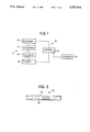
- FIG. 1 illustrates a schematic diagram in accordance with the principles of the present invention.
- FIG. 2 illustrates a sectional view of a dual diaphragm pump incorporating a control interface in accordance with the principles of the present invention.
- FIG. 3 illustrates an elevational view of a control rod in accordance with the embodiment illustrated in FIG. 2.
- FIG. 1 schematically shows a pump system 10 embodying the principles of the present invention.
- a pump assembly 12 includes a diaphragm pumping element 14 that is moved between a suction stroke and a discharge stroke by an actuator 16, for example, a solenoid-controlled multi-stage pneumatic cylinder or other suitable actuating mechanism.
- a diaphragm follower 18 is connected to the diaphragm for movement therewith during operation of the pump assembly 12.
- a sensor mechanism 20 is connected in proximity to the diaphragm follower 18. The sensor 20 senses the position and rate of movement of the diaphragm 14 by sensing the position and speed of movement of the diaphragm follower 18. It is contemplated that the sensor and diaphragm follower could be provided as a variety of interactive elements.
- the diaphragm follower could be provided as a rod connected to the diaphragm, with the rod including a plurality of sensor detectable indicia which are capable of being read by the sensor.
- the indica could be a plurality of conductive targets on the rod, and the sensor could be provided as a proximity switch adapted to produce a pulsed output signal when in a predetermined proximity with the conductive targets.
- the indicia could be provided as a plurality of optically readable targets disposed on the rod, and the sensor could be provided as an optical scanner.
- the indicia could be provided as a plurality of textured regions on the rod, and the sensor could be provided as an electron beam sensor.
- the follower and sensor could be provided as an arrangement employing sonic detection.
- the senor is capable of detecting at least the position and rate of movement of the diaphragm by sensing the position and rate of movement of the diaphragm follower.
- the sensor 20 is capable of generating signals corresponding to movement of the diaphragm follower 18. Signals from the sensor 20 are transmitted to a central control unit 22, for example, a microprocessor.
- the control unit 22 is adapted to generate control signals to control operation of the actuator 16.
- the control unit 22 may receive additional input from sensors 23.
- the sensors 23 can be provided as inline flow condition sensors such as flow rate sensors, concentration sensors, and flow volume sensors, or as pump condition sensors, such as actuator displacement sensors. Examples of such sensors are provided in copending application U.S. Ser. No. 07/871,191, filed on Apr. 20, 1992 and assigned to the assignee of the present invention, the specification of which is incorporated by reference herein.
- the ability of the central control unit 22 to monitor diaphragm movement through the follower 18 and the sensor 20 allows the control unit 20 to, when necessary, change the pump speed or cycle pattern of the pump assembly 12 in response to changes in pumped fluid characteristics.
- the control unit 22 could be used to monitor pump flow rate based on a pump displacement factor and the pulse rate output from the follower 18 and sensor 20. Additionally, the pulse rate of normal operation could be sampled and stored for later comparison in the control unit 22. This would allow operational problems or changes in pump fluid characteristics to be easily identified and corrected by the control unit 22.
- FIGS. 2 and 3 illustrate an embodiment of the present invention which represents the best mode currently known by the inventor for practicing the invention.
- FIG. 2 illustrates a pump assembly 24.
- the pump assembly 24, with the exception of the specific construction relating to the present invention, is similar to a standard double-diaphragm pump marketed by the assignee of the present invention as the SANDPIPER Model PB3/4-A Type 3 pump.
- the pump assembly 24 operates in accordance with the characteristics set forth in the background of the invention.
- the pump assembly 24 includes a first diaphragm 26 disposed for reciprocation within a first half of the pump assembly 24 and a second diaphragm 28 disposed within a second half 29 of the pump assembly 24.
- the diaphragm 26 is connected for synchronous movement with the diaphragm 26 by a diaphragm rod 30.
- the diaphragm rod 30 is provided with a plurality of conductive targets 32a along its length, as will be described in detail hereinbelow.
- the rod 30 is disposed for reciprocable movement within a bore 34 in a central housing portion 36 of the pump assembly 24.
- a plurality of rod seals 38 are provided to seal the rod 30 and bore 34 against contamination.
- the rod 30 is provided with a plurality of conductive indicia or targets 40 at spaced intervals along its length.
- the indicia or targets 40 are provided in the form of annular bands having a diameter equal to the diameter of the rod, so that reciprocation of the rod 30 through the bore 34 is not impeded, and the seal affected by the rod seals 38 is maintained.
- the proximity switch 42 is disposed within a sealed chamber 43 and may be provided, for example, as a type "E" three-wired DC, self contained proximity sensor, manufactured by "Pepperl+Fuchs, Inc.”.
- a plurality of leads 44 extend from the proximity switch 42 to a controller, in accordance with the general description of FIG. 1.
- the illustrated embodiment shows the proximity sensor 42 in the sealed chamber 43 as being directly exposed to the indicia 40, it is also contemplated that a further containment wall or seal could be used between the indicia and the sensor.
- Such a seal would have to be "transparent" to the interaction between the indicia and the sensor, so that the indicia remained detectably exposed to the sensor.
- the additional seal would have to be of non-conductive material.
- the additional seal would have to allow for the passage of light.
- FIG. 3 shows a more detailed view of the rod 30.
- the rod 30 includes a plurality of conductive targets 40, which are defined by non-conductive portions 46.
- the rod 30 can be manufactured by forming a series of undercuts along the length of a standard stainless steel diaphragm rod. The undercuts are then filled with a non-conductive material, for example a ceramic, to bring the rod back to its full outside diameter. The rod is then finished to produce a smooth, uninterrupted surface so that the rod may travel through the seal bearings and shaft seals unimpeded.
- the non-conductive material is transparent to the proximity switch, which senses only the original material steps or targets spaced between the filler material.
- the rod 30 reciprocates in the bore 34, causing the targets 40 to pass by the proximity switch 42.
- the proximity switch As each of the targets passes by the proximity switch, the proximity switch generates a pulses output signal that travels through the leads 44 to a central controller.
- the central controller contains a clock mechanism of conventional structure, and can thus determine the elapsed time between pulse signals, thus determining the speed of reciprocation of the rod 30, and thus of the diaphragms 26 and 28. It is also contemplated that the control unit would have the capability of using changes in the speed of travel of the diaphragms to calculate acceleration and other speed-dependent characteristics.
- the direction of travel of the diaphragm follower rod 30 could also be sensed, for example, by providing the targets 40 with predetermined, varying widths.
Landscapes
- Engineering & Computer Science (AREA)
- Mechanical Engineering (AREA)
- General Engineering & Computer Science (AREA)
- Physics & Mathematics (AREA)
- General Physics & Mathematics (AREA)
- Reciprocating Pumps (AREA)
Abstract
Description
Claims (15)
Priority Applications (3)
| Application Number | Priority Date | Filing Date | Title |
|---|---|---|---|
| US07/903,341 US5257914A (en) | 1992-06-24 | 1992-06-24 | Electronic control interface for fluid powered diaphragm pump |
| EP93109945A EP0578999B1 (en) | 1992-06-24 | 1993-06-22 | Electronic control interface for fluid powered diaphragm pump |
| DE69302765T DE69302765T2 (en) | 1992-06-24 | 1993-06-22 | Electronic sensor device for a fluid-driven diaphragm pump |
Applications Claiming Priority (1)
| Application Number | Priority Date | Filing Date | Title |
|---|---|---|---|
| US07/903,341 US5257914A (en) | 1992-06-24 | 1992-06-24 | Electronic control interface for fluid powered diaphragm pump |
Publications (1)
| Publication Number | Publication Date |
|---|---|
| US5257914A true US5257914A (en) | 1993-11-02 |
Family
ID=25417341
Family Applications (1)
| Application Number | Title | Priority Date | Filing Date |
|---|---|---|---|
| US07/903,341 Expired - Lifetime US5257914A (en) | 1992-06-24 | 1992-06-24 | Electronic control interface for fluid powered diaphragm pump |
Country Status (3)
| Country | Link |
|---|---|
| US (1) | US5257914A (en) |
| EP (1) | EP0578999B1 (en) |
| DE (1) | DE69302765T2 (en) |
Cited By (38)
| Publication number | Priority date | Publication date | Assignee | Title |
|---|---|---|---|---|
| US5816778A (en) * | 1996-01-16 | 1998-10-06 | Micron Technology, Inc. | System for controlling the stroke length of a double-diaphragm pump |
| US6024540A (en) * | 1995-09-22 | 2000-02-15 | Navarro Bonet; Jose Manuel | Pump for pumping through a variable volume plunger chamber having a pair of plungers disposed in a stepped cylinder with a slide valve |
| US6036445A (en) * | 1998-02-27 | 2000-03-14 | Warren Rupp, Inc. | Electric shifting mechanism/interface for fluid power diaphragm pumps |
| US6168387B1 (en) | 1999-10-28 | 2001-01-02 | Ingersoll-Rand Company | Reciprocating pump with linear displacement sensor |
| US6241487B1 (en) * | 1998-11-10 | 2001-06-05 | Warren Rupp, Inc. | Fluid powered diaphragm pump |
| US6280149B1 (en) * | 1999-10-28 | 2001-08-28 | Ingersoll-Rand Company | Active feedback apparatus and air driven diaphragm pumps incorporating same |
| US20060104829A1 (en) * | 2004-11-17 | 2006-05-18 | Reed David A | Control system for an air operated diaphragm pump |
| US20070092386A1 (en) * | 2005-10-24 | 2007-04-26 | Reed David A | Method and control system for a pump |
| US20080003120A1 (en) * | 2006-06-30 | 2008-01-03 | Meza Humberto V | Pump apparatus and method |
| US20090202361A1 (en) * | 2004-11-17 | 2009-08-13 | Proportion, Inc. | Control system for an air operated diaphragm pump |
| US20100040490A1 (en) * | 2008-08-12 | 2010-02-18 | Anis Rahman | Volumetric Infusion Pump and Method |
| US20100189577A1 (en) * | 2009-01-23 | 2010-07-29 | Idex Aodd, Inc. | Method for Increasing Compressed Air Efficiency In a Pump |
| US20100196168A1 (en) * | 2009-01-30 | 2010-08-05 | Nicholas Kozumplik | Pump end of stroke sensor |
| US20100284834A1 (en) * | 2009-05-08 | 2010-11-11 | Idex Aodd, Inc. | Air Operated Diaphragm Pump With Electric Generator |
| US20110142692A1 (en) * | 2009-12-16 | 2011-06-16 | Idex Aodd, Inc. | Air Logic Controller |
| US20110236224A1 (en) * | 2010-03-29 | 2011-09-29 | Glauber Carl J | Air-Driven Pump System |
| WO2012044445A1 (en) * | 2010-10-01 | 2012-04-05 | Franklin Electric Company, Inc. | Solenoid pump |
| USD692923S1 (en) | 2013-01-14 | 2013-11-05 | Ingersoll-Rand Company | Pump |
| CN103925198A (en) * | 2013-01-14 | 2014-07-16 | 英古所连公司 | Diaphragm Pump With Muffler-mounted Sensor |
| US8926291B2 (en) | 2010-07-19 | 2015-01-06 | Michael Orndorff | Speed control for diaphragm pump |
| US20160195081A1 (en) * | 2008-12-19 | 2016-07-07 | Stobbe Tech A/S | Electronically controlled diaphragm pump |
| US20170037839A1 (en) * | 2012-06-15 | 2017-02-09 | Stephen B. Maguire | Pump actuator and method for pump operation |
| EP3171026A1 (en) * | 2015-11-23 | 2017-05-24 | Bee Cheong Teh | Air-operated double diaphragm pump |
| US20170298919A1 (en) * | 2016-04-18 | 2017-10-19 | Ingersoll-Rand Company | Direct drive linear motor for conventionally arranged double diaphragm pump |
| US10036378B2 (en) | 2013-02-28 | 2018-07-31 | Ingersoll-Rand Company | Positive displacement pump with pressure compensating calibration |
| US10054115B2 (en) | 2013-02-11 | 2018-08-21 | Ingersoll-Rand Company | Diaphragm pump with automatic priming function |
| WO2019028267A1 (en) * | 2017-08-03 | 2019-02-07 | Repligen Corporation | Method of actuation of an alternating tangential flow diaphragm pump |
| CN110582639A (en) * | 2017-05-03 | 2019-12-17 | 巴斯夫涂料有限公司 | Pump assembly for conveying viscous media, device comprising the pump assembly, method for producing a surface coating composition and use of the pump assembly |
| US10597513B2 (en) | 2013-07-17 | 2020-03-24 | Stephen B. Maguire | Cottonseed oil based additive compositions for plastics molding and extrusion |
| US10731641B2 (en) * | 2013-01-14 | 2020-08-04 | Ingersoll-Rand Industrial U.S., Inc. | Diaphragm pump with sensor mount |
| US10767031B2 (en) | 2013-07-17 | 2020-09-08 | Stephen B. Maguire | Cottonseed oil based liquid color composition and plastics coloring method using the same |
| US20200400136A1 (en) * | 2019-06-21 | 2020-12-24 | Clean Energy Labs, Llc | Venturi Pump Systems And Methods To Use Same |
| US11022106B2 (en) | 2018-01-09 | 2021-06-01 | Graco Minnesota Inc. | High-pressure positive displacement plunger pump |
| US11174854B2 (en) | 2020-03-31 | 2021-11-16 | Graco Minnesota Inc. | Electrically operated displacement pump control system and method |
| US11795297B2 (en) | 2013-07-17 | 2023-10-24 | Stephen B. Maguire | Plastics coloring using cottonseed oil-based liquid color compositions |
| US11867165B2 (en) | 2014-02-07 | 2024-01-09 | Graco Minnesota Inc. | Drive system for a positive displacement pump |
| US12345248B2 (en) | 2019-03-13 | 2025-07-01 | Psg Germany Gmbh | Valve assemblies for a diaphragm pump |
| US12366233B2 (en) | 2020-03-31 | 2025-07-22 | Graco Minnesota Inc. | Electrically operated pump for a plural component spray system |
Families Citing this family (19)
| Publication number | Priority date | Publication date | Assignee | Title |
|---|---|---|---|---|
| DE19904106C2 (en) * | 1999-02-02 | 2001-06-28 | Oskar Bschorr | Sound generator with pump drive |
| GB0224986D0 (en) | 2002-10-28 | 2002-12-04 | Smith & Nephew | Apparatus |
| EP1515044A1 (en) * | 2003-09-11 | 2005-03-16 | Franco De Bernardi | Diaphragm pump for fluids |
| SE529328C2 (en) | 2005-11-15 | 2007-07-10 | Johan Stenberg | Control system and method for controlling electromagnetically driven pumps |
| CA2604623C (en) | 2006-09-28 | 2018-10-30 | Tyco Healthcare Group Lp | Portable wound therapy system |
| GB0723855D0 (en) | 2007-12-06 | 2008-01-16 | Smith & Nephew | Apparatus and method for wound volume measurement |
| GB201011173D0 (en) | 2010-07-02 | 2010-08-18 | Smith & Nephew | Provision of wound filler |
| GB201015656D0 (en) | 2010-09-20 | 2010-10-27 | Smith & Nephew | Pressure control apparatus |
| WO2012069794A1 (en) | 2010-11-25 | 2012-05-31 | Smith & Nephew Plc | Composition i-ii and products and uses thereof |
| GB201020005D0 (en) | 2010-11-25 | 2011-01-12 | Smith & Nephew | Composition 1-1 |
| US9084845B2 (en) | 2011-11-02 | 2015-07-21 | Smith & Nephew Plc | Reduced pressure therapy apparatuses and methods of using same |
| US20150159066A1 (en) | 2011-11-25 | 2015-06-11 | Smith & Nephew Plc | Composition, apparatus, kit and method and uses thereof |
| US9427505B2 (en) | 2012-05-15 | 2016-08-30 | Smith & Nephew Plc | Negative pressure wound therapy apparatus |
| EP2968647B1 (en) | 2013-03-15 | 2022-06-29 | Smith & Nephew plc | Wound dressing sealant and use thereof |
| US20160120706A1 (en) | 2013-03-15 | 2016-05-05 | Smith & Nephew Plc | Wound dressing sealant and use thereof |
| WO2016103033A2 (en) | 2014-12-22 | 2016-06-30 | Smith & Nephew Plc | Negative pressure wound therapy apparatus and methods |
| DE102015108964B4 (en) * | 2015-06-08 | 2019-11-14 | Timmer Gmbh | Method for controlling a diaphragm pump, in particular a double diaphragm pump |
| DE102015108963B4 (en) * | 2015-06-08 | 2019-11-14 | Timmer Gmbh | Pneumatically operated diaphragm pump, in particular double diaphragm pump |
| DE102024103539A1 (en) * | 2024-02-08 | 2025-08-14 | Timmer Gmbh | Sensor-controlled diaphragm pump |
Citations (9)
| Publication number | Priority date | Publication date | Assignee | Title |
|---|---|---|---|---|
| US2832919A (en) * | 1953-03-10 | 1958-04-29 | Reutter Jean Leon | Movable equipment for electro-magnetically controlled devices |
| US3782863A (en) * | 1971-11-16 | 1974-01-01 | Rupp Co Warren | Slide valve apparatus |
| US4345442A (en) * | 1980-06-17 | 1982-08-24 | Mechanical Technology Incorporated | Control system for resonant free-piston variable stroke compressor for load-following electric heat pumps and the like |
| US4436493A (en) * | 1979-09-21 | 1984-03-13 | The Coca-Cola Company | Self contained pump and reversing mechanism therefor |
| US4472115A (en) * | 1982-09-07 | 1984-09-18 | The Warren Rupp Company | Fluid-operated reciprocating pump |
| US4682937A (en) * | 1981-11-12 | 1987-07-28 | The Coca-Cola Company | Double-acting diaphragm pump and reversing mechanism therefor |
| US4927335A (en) * | 1987-11-04 | 1990-05-22 | O.D.L. S.R.L. | Pump for transferring liquids, in particular beer or carbonated beverages |
| US5076890A (en) * | 1989-03-16 | 1991-12-31 | Dorr-Oliver Incorporated | Method for pulp quality control and regulation |
| US5174731A (en) * | 1989-01-12 | 1992-12-29 | DEPA Gesellschaft fur Verfahrenstecnik mit beschrankter Haftung | Method and arrangement for controlling a compressed air-operated double diaphragm pump |
Family Cites Families (4)
| Publication number | Priority date | Publication date | Assignee | Title |
|---|---|---|---|---|
| DE2933557C2 (en) * | 1979-08-18 | 1982-11-04 | Robert Bosch Gmbh, 7000 Stuttgart | Transmitter for non-contact distance or speed measurement |
| GB2157831A (en) * | 1984-04-06 | 1985-10-30 | Emhart Ind | Magnetically monitoring the movement of a rod |
| NL9101556A (en) * | 1991-09-16 | 1993-04-16 | Holthuis Bv | CONTROL SYSTEM FOR PISTON MEMBRANE PUMP. |
| DE4135206A1 (en) * | 1991-10-25 | 1993-04-29 | Bosch Gmbh Robert | Contactless speed measuring appts. for determining velocity of workpiece carrier on conveyor - has pulse receivers arranged along path of motion detecting pulses from markers on objects |
-
1992
- 1992-06-24 US US07/903,341 patent/US5257914A/en not_active Expired - Lifetime
-
1993
- 1993-06-22 DE DE69302765T patent/DE69302765T2/en not_active Expired - Fee Related
- 1993-06-22 EP EP93109945A patent/EP0578999B1/en not_active Expired - Lifetime
Patent Citations (9)
| Publication number | Priority date | Publication date | Assignee | Title |
|---|---|---|---|---|
| US2832919A (en) * | 1953-03-10 | 1958-04-29 | Reutter Jean Leon | Movable equipment for electro-magnetically controlled devices |
| US3782863A (en) * | 1971-11-16 | 1974-01-01 | Rupp Co Warren | Slide valve apparatus |
| US4436493A (en) * | 1979-09-21 | 1984-03-13 | The Coca-Cola Company | Self contained pump and reversing mechanism therefor |
| US4345442A (en) * | 1980-06-17 | 1982-08-24 | Mechanical Technology Incorporated | Control system for resonant free-piston variable stroke compressor for load-following electric heat pumps and the like |
| US4682937A (en) * | 1981-11-12 | 1987-07-28 | The Coca-Cola Company | Double-acting diaphragm pump and reversing mechanism therefor |
| US4472115A (en) * | 1982-09-07 | 1984-09-18 | The Warren Rupp Company | Fluid-operated reciprocating pump |
| US4927335A (en) * | 1987-11-04 | 1990-05-22 | O.D.L. S.R.L. | Pump for transferring liquids, in particular beer or carbonated beverages |
| US5174731A (en) * | 1989-01-12 | 1992-12-29 | DEPA Gesellschaft fur Verfahrenstecnik mit beschrankter Haftung | Method and arrangement for controlling a compressed air-operated double diaphragm pump |
| US5076890A (en) * | 1989-03-16 | 1991-12-31 | Dorr-Oliver Incorporated | Method for pulp quality control and regulation |
Cited By (77)
| Publication number | Priority date | Publication date | Assignee | Title |
|---|---|---|---|---|
| US6024540A (en) * | 1995-09-22 | 2000-02-15 | Navarro Bonet; Jose Manuel | Pump for pumping through a variable volume plunger chamber having a pair of plungers disposed in a stepped cylinder with a slide valve |
| US5816778A (en) * | 1996-01-16 | 1998-10-06 | Micron Technology, Inc. | System for controlling the stroke length of a double-diaphragm pump |
| US6036445A (en) * | 1998-02-27 | 2000-03-14 | Warren Rupp, Inc. | Electric shifting mechanism/interface for fluid power diaphragm pumps |
| US6241487B1 (en) * | 1998-11-10 | 2001-06-05 | Warren Rupp, Inc. | Fluid powered diaphragm pump |
| US6168387B1 (en) | 1999-10-28 | 2001-01-02 | Ingersoll-Rand Company | Reciprocating pump with linear displacement sensor |
| US6280149B1 (en) * | 1999-10-28 | 2001-08-28 | Ingersoll-Rand Company | Active feedback apparatus and air driven diaphragm pumps incorporating same |
| US8292600B2 (en) | 2004-11-17 | 2012-10-23 | Proportion-Air, Incorporated | Control system for an air operated diaphragm pump |
| US20060104829A1 (en) * | 2004-11-17 | 2006-05-18 | Reed David A | Control system for an air operated diaphragm pump |
| US7517199B2 (en) | 2004-11-17 | 2009-04-14 | Proportion Air Incorporated | Control system for an air operated diaphragm pump |
| US20090202361A1 (en) * | 2004-11-17 | 2009-08-13 | Proportion, Inc. | Control system for an air operated diaphragm pump |
| US20070092386A1 (en) * | 2005-10-24 | 2007-04-26 | Reed David A | Method and control system for a pump |
| US7658598B2 (en) | 2005-10-24 | 2010-02-09 | Proportionair, Incorporated | Method and control system for a pump |
| US20080003120A1 (en) * | 2006-06-30 | 2008-01-03 | Meza Humberto V | Pump apparatus and method |
| US20100040490A1 (en) * | 2008-08-12 | 2010-02-18 | Anis Rahman | Volumetric Infusion Pump and Method |
| US10508647B2 (en) | 2008-12-19 | 2019-12-17 | Stobbe Pharma Tech Gmbh | Electronically controlled diaphragm pump |
| US20160195081A1 (en) * | 2008-12-19 | 2016-07-07 | Stobbe Tech A/S | Electronically controlled diaphragm pump |
| US10288060B2 (en) * | 2008-12-19 | 2019-05-14 | Stobbe Pharma Tech Gmbh | Electronically controlled diaphragm pump |
| AU2010206569B2 (en) * | 2009-01-23 | 2012-06-14 | Warren Rupp, Inc. | Method for increasing compressed air efficiency in a pump |
| US8608460B2 (en) * | 2009-01-23 | 2013-12-17 | Warren Rupp, Inc. | Method and apparatus for increasing compressed air efficiency in a pump |
| CN102292548B (en) * | 2009-01-23 | 2014-11-05 | 沃伦鲁普公司 | Method for increasing compressed air efficiency in a pump |
| WO2010085744A3 (en) * | 2009-01-23 | 2010-10-07 | Idex Aodd, Inc. | Method for increasing compressed air efficiency in a pump |
| CN102292548A (en) * | 2009-01-23 | 2011-12-21 | 沃伦鲁普公司 | Method for increasing compressed air efficiency in a pump |
| US8801404B2 (en) * | 2009-01-23 | 2014-08-12 | Warren Rupp, Inc. | Method for increasing compressed air efficiency in a pump |
| US20100189577A1 (en) * | 2009-01-23 | 2010-07-29 | Idex Aodd, Inc. | Method for Increasing Compressed Air Efficiency In a Pump |
| US20140348667A1 (en) * | 2009-01-23 | 2014-11-27 | Warren Rupp, Inc. | Method for increasing compressed air efficiency in a pump |
| US9316218B2 (en) * | 2009-01-23 | 2016-04-19 | Warren Rupp, Inc. | Method and apparatus for increasing compressed air efficiency in a pump |
| US20140037465A1 (en) * | 2009-01-23 | 2014-02-06 | Warren Rupp, Inc. | Method for increasing compressed air efficiency in a pump |
| US8485792B2 (en) * | 2009-01-23 | 2013-07-16 | Warren Rupp, Inc. | Method for increasing compressed air efficiency in a pump |
| WO2010085744A2 (en) | 2009-01-23 | 2010-07-29 | Idex Aodd, Inc. | Method for increasing compressed air efficiency in a pump |
| WO2010088007A1 (en) * | 2009-01-30 | 2010-08-05 | Ingersoll Rand Company | Pump end of stroke sensor |
| US20100196168A1 (en) * | 2009-01-30 | 2010-08-05 | Nicholas Kozumplik | Pump end of stroke sensor |
| US8425208B2 (en) | 2009-05-08 | 2013-04-23 | Warren Rupp, Inc. | Air operated diaphragm pump with electric generator |
| US20100284834A1 (en) * | 2009-05-08 | 2010-11-11 | Idex Aodd, Inc. | Air Operated Diaphragm Pump With Electric Generator |
| US8382445B2 (en) | 2009-12-16 | 2013-02-26 | Warren Rupp, Inc. | Air logic controller |
| US20110142692A1 (en) * | 2009-12-16 | 2011-06-16 | Idex Aodd, Inc. | Air Logic Controller |
| US9127657B2 (en) | 2010-03-29 | 2015-09-08 | Wilden Pump And Engineering Llc | Air-driven pump system |
| US9541074B2 (en) | 2010-03-29 | 2017-01-10 | Wilden Pump And Engineering Llc | Air-driven pump system |
| US20110236224A1 (en) * | 2010-03-29 | 2011-09-29 | Glauber Carl J | Air-Driven Pump System |
| US8926291B2 (en) | 2010-07-19 | 2015-01-06 | Michael Orndorff | Speed control for diaphragm pump |
| WO2012044445A1 (en) * | 2010-10-01 | 2012-04-05 | Franklin Electric Company, Inc. | Solenoid pump |
| US20170037839A1 (en) * | 2012-06-15 | 2017-02-09 | Stephen B. Maguire | Pump actuator and method for pump operation |
| CN103925198A (en) * | 2013-01-14 | 2014-07-16 | 英古所连公司 | Diaphragm Pump With Muffler-mounted Sensor |
| CN103925198B (en) * | 2013-01-14 | 2016-09-07 | 英古所连公司 | There is the membrane pump of silencer installing type sensor |
| USD692923S1 (en) | 2013-01-14 | 2013-11-05 | Ingersoll-Rand Company | Pump |
| US9284956B2 (en) | 2013-01-14 | 2016-03-15 | Ingersoll-Rand Company | Diaphragm pump with muffler-mounted sensor |
| US10731641B2 (en) * | 2013-01-14 | 2020-08-04 | Ingersoll-Rand Industrial U.S., Inc. | Diaphragm pump with sensor mount |
| EP2754894A1 (en) * | 2013-01-14 | 2014-07-16 | Ingersoll-Rand Company | Diaphragm pump with muffler-mounted sensor |
| US10054115B2 (en) | 2013-02-11 | 2018-08-21 | Ingersoll-Rand Company | Diaphragm pump with automatic priming function |
| US10036378B2 (en) | 2013-02-28 | 2018-07-31 | Ingersoll-Rand Company | Positive displacement pump with pressure compensating calibration |
| US11602883B2 (en) | 2013-07-17 | 2023-03-14 | Riverdale Global, Llc | Cottonseed oil liquid color composition and method |
| US10597513B2 (en) | 2013-07-17 | 2020-03-24 | Stephen B. Maguire | Cottonseed oil based additive compositions for plastics molding and extrusion |
| US10767031B2 (en) | 2013-07-17 | 2020-09-08 | Stephen B. Maguire | Cottonseed oil based liquid color composition and plastics coloring method using the same |
| US11795297B2 (en) | 2013-07-17 | 2023-10-24 | Stephen B. Maguire | Plastics coloring using cottonseed oil-based liquid color compositions |
| US10919206B2 (en) | 2013-07-17 | 2021-02-16 | Stephen B. Maguire | Cottonseed oil based liquid color composition and plastics coloring method using the same |
| US12253071B2 (en) | 2014-02-07 | 2025-03-18 | Graco Minnesota Inc. | Drive system for a positive displacement pump |
| US11867165B2 (en) | 2014-02-07 | 2024-01-09 | Graco Minnesota Inc. | Drive system for a positive displacement pump |
| EP3171026A1 (en) * | 2015-11-23 | 2017-05-24 | Bee Cheong Teh | Air-operated double diaphragm pump |
| US20170298919A1 (en) * | 2016-04-18 | 2017-10-19 | Ingersoll-Rand Company | Direct drive linear motor for conventionally arranged double diaphragm pump |
| CN110582639A (en) * | 2017-05-03 | 2019-12-17 | 巴斯夫涂料有限公司 | Pump assembly for conveying viscous media, device comprising the pump assembly, method for producing a surface coating composition and use of the pump assembly |
| EP4091690A1 (en) * | 2017-08-03 | 2022-11-23 | Repligen Corporation | Method of actuation of an alternating tangential flow diaphragm pump |
| AU2018309053B2 (en) * | 2017-08-03 | 2023-06-29 | Repligen Corporation | Method of actuation of an alternating tangential flow diaphragm pump |
| WO2019028267A1 (en) * | 2017-08-03 | 2019-02-07 | Repligen Corporation | Method of actuation of an alternating tangential flow diaphragm pump |
| CN111093793A (en) * | 2017-08-03 | 2020-05-01 | 瑞普利金公司 | Actuating method of alternating tangential flow diaphragm pump |
| EP4091691A1 (en) * | 2017-08-03 | 2022-11-23 | Repligen Corporation | Method of actuation of an alternating tangential flow diaphragm pump |
| EP4112151A1 (en) * | 2017-08-03 | 2023-01-04 | Repligen Corporation | Method of actuation of an alternating tangential flow diaphragm pump |
| US11578301B2 (en) | 2017-08-03 | 2023-02-14 | Repligen Corporation | Method of actuation of an alternating tangential flow diaphragm pump |
| US11834646B2 (en) | 2017-08-03 | 2023-12-05 | Repligen Corporation | Method of actuation of an alternating tangential flow diaphragm pump |
| EP3661622A4 (en) * | 2017-08-03 | 2020-12-16 | Repligen Corporation | METHOD OF OPERATING AN ALTERNATING TANGENTIAL FLOW DIAPHRAGM PUMP |
| US11022106B2 (en) | 2018-01-09 | 2021-06-01 | Graco Minnesota Inc. | High-pressure positive displacement plunger pump |
| US12345248B2 (en) | 2019-03-13 | 2025-07-01 | Psg Germany Gmbh | Valve assemblies for a diaphragm pump |
| US20200400136A1 (en) * | 2019-06-21 | 2020-12-24 | Clean Energy Labs, Llc | Venturi Pump Systems And Methods To Use Same |
| US11898545B2 (en) * | 2019-06-21 | 2024-02-13 | Brane Audio, LLC | Venturi pump systems and methods to use same |
| US11174854B2 (en) | 2020-03-31 | 2021-11-16 | Graco Minnesota Inc. | Electrically operated displacement pump control system and method |
| US11655810B2 (en) | 2020-03-31 | 2023-05-23 | Graco Minnesota Inc. | Electrically operated displacement pump control system and method |
| US12092090B2 (en) | 2020-03-31 | 2024-09-17 | Graco Minnesota Inc. | Electrically operated displacement pump control system and method |
| US11434892B2 (en) | 2020-03-31 | 2022-09-06 | Graco Minnesota Inc. | Electrically operated displacement pump assembly |
| US12366233B2 (en) | 2020-03-31 | 2025-07-22 | Graco Minnesota Inc. | Electrically operated pump for a plural component spray system |
Also Published As
| Publication number | Publication date |
|---|---|
| DE69302765T2 (en) | 1996-10-02 |
| EP0578999A1 (en) | 1994-01-19 |
| EP0578999B1 (en) | 1996-05-22 |
| DE69302765D1 (en) | 1996-06-27 |
Similar Documents
| Publication | Publication Date | Title |
|---|---|---|
| US5257914A (en) | Electronic control interface for fluid powered diaphragm pump | |
| US4681513A (en) | Two-stage pump assembly | |
| US6280149B1 (en) | Active feedback apparatus and air driven diaphragm pumps incorporating same | |
| US5312233A (en) | Linear liquid dispensing pump for dispensing liquid in nanoliter volumes | |
| US4919649A (en) | Fluid delivery system | |
| CN1136393C (en) | Diaphragm pump | |
| US20150300335A1 (en) | Reciprocating pump with electronically monitored air valve and piston | |
| CN101443551B (en) | Method and apparatus for controlling fluid flow | |
| KR900018535A (en) | Variable displacement swash plate compressor | |
| US6398514B1 (en) | Double-acting rod pump | |
| WO1998036172A1 (en) | High pressure pump | |
| CN109195711B (en) | Coating agent pump | |
| JPH02501329A (en) | Flow measuring device for measuring volumetric flow | |
| JPS6343591B2 (en) | ||
| EP0080466A1 (en) | Hydraulic linear actuator | |
| US6004117A (en) | Displacement pump | |
| CN207168787U (en) | A kind of syringe pump | |
| JPH04311685A (en) | Compressor | |
| JP2559414B2 (en) | Pulseless pump controller | |
| JP2511753Y2 (en) | Reciprocating pump | |
| CN220354020U (en) | Novel plunger infusion pump | |
| US4070910A (en) | Fluid flow measuring apparatus | |
| WO2000047894A1 (en) | Trace liquid suction and discharge device | |
| KR19990024092A (en) | Cylinder pressure sensor | |
| JPS5937454B2 (en) | Pressure differential display device for fluid measuring bridges |
Legal Events
| Date | Code | Title | Description |
|---|---|---|---|
| AS | Assignment |
Owner name: WARREN RUPP, INC., OHIO Free format text: ASSIGNMENT OF ASSIGNORS INTEREST.;ASSIGNOR:REYNOLDS, STEVEN M.;REEL/FRAME:006171/0678 Effective date: 19920616 |
|
| STCF | Information on status: patent grant |
Free format text: PATENTED CASE |
|
| FEPP | Fee payment procedure |
Free format text: PAYOR NUMBER ASSIGNED (ORIGINAL EVENT CODE: ASPN); ENTITY STATUS OF PATENT OWNER: LARGE ENTITY |
|
| FPAY | Fee payment |
Year of fee payment: 4 |
|
| FPAY | Fee payment |
Year of fee payment: 8 |
|
| SULP | Surcharge for late payment |
Year of fee payment: 7 |
|
| REMI | Maintenance fee reminder mailed | ||
| FPAY | Fee payment |
Year of fee payment: 12 |
|
| SULP | Surcharge for late payment |
Year of fee payment: 11 |