US5256347A - Method of firing ceramic honeycomb structure - Google Patents
Method of firing ceramic honeycomb structure Download PDFInfo
- Publication number
- US5256347A US5256347A US07/952,150 US95215092A US5256347A US 5256347 A US5256347 A US 5256347A US 95215092 A US95215092 A US 95215092A US 5256347 A US5256347 A US 5256347A
- Authority
- US
- United States
- Prior art keywords
- ceramic honeycomb
- temperature
- outside
- honeycomb structure
- firing
- Prior art date
- Legal status (The legal status is an assumption and is not a legal conclusion. Google has not performed a legal analysis and makes no representation as to the accuracy of the status listed.)
- Expired - Fee Related
Links
- 238000010304 firing Methods 0.000 title claims abstract description 50
- 239000000919 ceramic Substances 0.000 title claims abstract description 38
- 238000000034 method Methods 0.000 title claims abstract description 21
- 238000002485 combustion reaction Methods 0.000 claims abstract description 28
- 239000006259 organic additive Substances 0.000 claims 2
- 239000003795 chemical substances by application Substances 0.000 abstract description 39
- 230000001105 regulatory effect Effects 0.000 abstract description 3
- 230000001276 controlling effect Effects 0.000 abstract 1
- 238000010438 heat treatment Methods 0.000 abstract 1
- 238000000465 moulding Methods 0.000 description 33
- 239000005995 Aluminium silicate Substances 0.000 description 15
- PNEYBMLMFCGWSK-UHFFFAOYSA-N aluminium oxide Inorganic materials [O-2].[O-2].[O-2].[Al+3].[Al+3] PNEYBMLMFCGWSK-UHFFFAOYSA-N 0.000 description 15
- 235000012211 aluminium silicate Nutrition 0.000 description 15
- NLYAJNPCOHFWQQ-UHFFFAOYSA-N kaolin Chemical compound O.O.O=[Al]O[Si](=O)O[Si](=O)O[Al]=O NLYAJNPCOHFWQQ-UHFFFAOYSA-N 0.000 description 15
- 239000000203 mixture Substances 0.000 description 15
- QVGXLLKOCUKJST-UHFFFAOYSA-N atomic oxygen Chemical compound [O] QVGXLLKOCUKJST-UHFFFAOYSA-N 0.000 description 12
- 229910052760 oxygen Inorganic materials 0.000 description 12
- 239000001301 oxygen Substances 0.000 description 12
- 239000000454 talc Substances 0.000 description 10
- 229910052623 talc Inorganic materials 0.000 description 10
- 229920002472 Starch Polymers 0.000 description 9
- 239000000428 dust Substances 0.000 description 9
- 239000008107 starch Substances 0.000 description 9
- 235000019698 starch Nutrition 0.000 description 9
- 238000002474 experimental method Methods 0.000 description 8
- OKTJSMMVPCPJKN-UHFFFAOYSA-N Carbon Chemical compound [C] OKTJSMMVPCPJKN-UHFFFAOYSA-N 0.000 description 7
- 229910010293 ceramic material Inorganic materials 0.000 description 7
- 239000010439 graphite Substances 0.000 description 7
- 229910002804 graphite Inorganic materials 0.000 description 7
- 238000004519 manufacturing process Methods 0.000 description 7
- PEDCQBHIVMGVHV-UHFFFAOYSA-N Glycerine Chemical compound OCC(O)CO PEDCQBHIVMGVHV-UHFFFAOYSA-N 0.000 description 6
- 229920000609 methyl cellulose Polymers 0.000 description 6
- 239000001923 methylcellulose Substances 0.000 description 6
- 235000010981 methylcellulose Nutrition 0.000 description 6
- 230000003247 decreasing effect Effects 0.000 description 5
- KZHJGOXRZJKJNY-UHFFFAOYSA-N dioxosilane;oxo(oxoalumanyloxy)alumane Chemical compound O=[Si]=O.O=[Si]=O.O=[Al]O[Al]=O.O=[Al]O[Al]=O.O=[Al]O[Al]=O KZHJGOXRZJKJNY-UHFFFAOYSA-N 0.000 description 5
- 238000002156 mixing Methods 0.000 description 5
- 229910052863 mullite Inorganic materials 0.000 description 5
- 238000001035 drying Methods 0.000 description 4
- 235000013312 flour Nutrition 0.000 description 4
- 230000036760 body temperature Effects 0.000 description 3
- 238000012790 confirmation Methods 0.000 description 3
- 235000011187 glycerol Nutrition 0.000 description 3
- 239000000463 material Substances 0.000 description 3
- 229920002134 Carboxymethyl cellulose Polymers 0.000 description 2
- 239000004372 Polyvinyl alcohol Substances 0.000 description 2
- 239000011230 binding agent Substances 0.000 description 2
- 239000001768 carboxy methyl cellulose Substances 0.000 description 2
- 235000010948 carboxy methyl cellulose Nutrition 0.000 description 2
- 239000008112 carboxymethyl-cellulose Substances 0.000 description 2
- 229910052878 cordierite Inorganic materials 0.000 description 2
- JSKIRARMQDRGJZ-UHFFFAOYSA-N dimagnesium dioxido-bis[(1-oxido-3-oxo-2,4,6,8,9-pentaoxa-1,3-disila-5,7-dialuminabicyclo[3.3.1]nonan-7-yl)oxy]silane Chemical compound [Mg++].[Mg++].[O-][Si]([O-])(O[Al]1O[Al]2O[Si](=O)O[Si]([O-])(O1)O2)O[Al]1O[Al]2O[Si](=O)O[Si]([O-])(O1)O2 JSKIRARMQDRGJZ-UHFFFAOYSA-N 0.000 description 2
- 238000001125 extrusion Methods 0.000 description 2
- 230000020169 heat generation Effects 0.000 description 2
- 238000012986 modification Methods 0.000 description 2
- 230000004048 modification Effects 0.000 description 2
- 229920003023 plastic Polymers 0.000 description 2
- 229920002451 polyvinyl alcohol Polymers 0.000 description 2
- 235000019422 polyvinyl alcohol Nutrition 0.000 description 2
- 239000004094 surface-active agent Substances 0.000 description 2
- 235000013339 cereals Nutrition 0.000 description 1
- 238000007796 conventional method Methods 0.000 description 1
- 238000009826 distribution Methods 0.000 description 1
- 238000011068 loading method Methods 0.000 description 1
- 238000005259 measurement Methods 0.000 description 1
- 238000012544 monitoring process Methods 0.000 description 1
- 238000012545 processing Methods 0.000 description 1
- 239000007787 solid Substances 0.000 description 1
- JYKSTGLAIMQDRA-UHFFFAOYSA-N tetraglycerol Chemical compound OCC(O)CO.OCC(O)CO.OCC(O)CO.OCC(O)CO JYKSTGLAIMQDRA-UHFFFAOYSA-N 0.000 description 1
- 238000009827 uniform distribution Methods 0.000 description 1
- 238000011179 visual inspection Methods 0.000 description 1
- 238000005303 weighing Methods 0.000 description 1
Images


Classifications
-
- B—PERFORMING OPERATIONS; TRANSPORTING
- B01—PHYSICAL OR CHEMICAL PROCESSES OR APPARATUS IN GENERAL
- B01D—SEPARATION
- B01D39/00—Filtering material for liquid or gaseous fluids
- B01D39/14—Other self-supporting filtering material ; Other filtering material
- B01D39/20—Other self-supporting filtering material ; Other filtering material of inorganic material, e.g. asbestos paper, metallic filtering material of non-woven wires
- B01D39/2068—Other inorganic materials, e.g. ceramics
- B01D39/2072—Other inorganic materials, e.g. ceramics the material being particulate or granular
- B01D39/2075—Other inorganic materials, e.g. ceramics the material being particulate or granular sintered or bonded by inorganic agents
-
- C—CHEMISTRY; METALLURGY
- C04—CEMENTS; CONCRETE; ARTIFICIAL STONE; CERAMICS; REFRACTORIES
- C04B—LIME, MAGNESIA; SLAG; CEMENTS; COMPOSITIONS THEREOF, e.g. MORTARS, CONCRETE OR LIKE BUILDING MATERIALS; ARTIFICIAL STONE; CERAMICS; REFRACTORIES; TREATMENT OF NATURAL STONE
- C04B35/00—Shaped ceramic products characterised by their composition; Ceramics compositions; Processing powders of inorganic compounds preparatory to the manufacturing of ceramic products
- C04B35/622—Forming processes; Processing powders of inorganic compounds preparatory to the manufacturing of ceramic products
- C04B35/64—Burning or sintering processes
-
- C—CHEMISTRY; METALLURGY
- C04—CEMENTS; CONCRETE; ARTIFICIAL STONE; CERAMICS; REFRACTORIES
- C04B—LIME, MAGNESIA; SLAG; CEMENTS; COMPOSITIONS THEREOF, e.g. MORTARS, CONCRETE OR LIKE BUILDING MATERIALS; ARTIFICIAL STONE; CERAMICS; REFRACTORIES; TREATMENT OF NATURAL STONE
- C04B38/00—Porous mortars, concrete, artificial stone or ceramic ware; Preparation thereof
- C04B38/0006—Honeycomb structures
Definitions
- This invention relates to a method which is suitable for firing a ceramic honeycomb structure.
- a ceramic product of honeycomb shape, or a ceramic honeycomb structure has been made by preparing a ceramic green body through mixing of ceramic materials with a molding aids and a pore-forming agent, molding the body into a honeycomb-shaped ceramic green body through extrusion of the mixed body, and finally firing the honeycomb-shaped ceramic green body in a firing furnace at a predetermined temperature.
- the molding aids to be mixed with the ceramic materials for the above firing of the honeycomb structure are for instance an organic binder, such as methyl cellulose, carboxymethylcellulose, polyvinyl alcohol, starch paste, flour, glycerin, and the like or a surface active agent, or wax, etc.
- the above pore-forming agent to be used with the ceramic materials is for instance graphite, saw dust, starch etc.
- Such molding aids and pore-forming agent have the following special properties; namely, the molding aids or pore-forming agent is hard to heat from the outside of the honeycomb structure, but once ignited, burns rapidly and generates heat (the igniting temperature varies depending on the kind of auxiliary).
- the rapid burning of the molding aids or pore-forming agent results in uneven temperature distribution in the structure and tends to cause cracks within or at end portions of the final ceramic honeycomb structure.
- the oxygen concentration in the firing atmosphere at a temperature in ignition ranges of the molding aids or pore-forming agent varies depending on fluctuation of the weight of ceramic green body loaded in the furnace (to be referred to as "the loaded weight", hereinafter).
- the manner in which the molding aids or pore-forming agent within the ceramic honeycomb body burns varies, so that the temperature difference between the inside and outer portions of the ceramic honeycomb body becomes large or small. In consequence, sometimes cracks generate but sometimes not, resulting in a problem that the quality of the product is not uniform and stable production is hard to realize.
- the pore-forming agent comes in contact with oxygen of the firing atmosphere and burns out in a certain time period, so as to produce fine holes of a desired diameter. It has been a practice to terminate the firing process with a certain time relationship with the timing of the burn out of the pore-forming agent.
- the oxygen concentration in the firing atmosphere varies and the kind of pore-forming agent varies, so that the burning characteristics of the pore-forming agent changes.
- an object of the present invention is to solve the above-mentioned problems of the prior art by providing an improved method of firing ceramic honeycomb structures which ensures stable production of a high-quality product.
- An object of the invention is to provide a method of firing a ceramic honeycomb structure at a predetermined temperature in a predetermined atmosphere, characterized in that temperatures at inside and outside portions of the ceramic honeycomb structure are detected by a temperature sensing means, and combustion of burner means is controlled based on the temperatures thus detected.
- the temperatures at the inside and outside portions of the ceramic honeycomb structure are detected, and based on the detected temperatures, the outside temperature is controlled relative to the inside temperature by regulating the combustion of a burner means which heats the ceramic honeycomb structure from the outside thereof.
- a burner means which heats the ceramic honeycomb structure from the outside thereof.
- the heat supply from the burner means will be increased so as to raise the outside temperature to a level corresponding to the inside temperature.
- the heat supply from the burner means will be decreased so as to suppress the outside temperature.
- the outside temperature of the body being fired coincides with the inside temperature thereof.
- the combustion of a burner means is controlled while detecting and monitoring the inside and outside temperatures until the above temperature coincidence is reached, for instance by keeping constant combustion in the vicinity of the above coincidence. With such control, stable firing can be effected even when the burning characteristics of the pore-forming agent varies due to fluctuation in the loaded weight of shaped bodies or due to change in the state of the pore-forming agent, and such stable firing enables production of high-quality goods.
- FIG. 1 is a sectional view of a firing furnace to be used for working the firing method according to the present invention
- FIG. 2a through FIG. 4b are graphs showing temperature variations at the inside and outside portions of specimens of shaped body when such specimens were heated in the ensuing Experiments 1 through 3, covering both the method of the invention and a conventional method;
- FIG. 5 is a graph showing how the burn out of a pore-forming agent is reflected in the temperature change of a shaped body being fired.
- a shaped body Before firing a ceramic honeycomb structure by the method of the invention, a shaped body is prepared at first by mixing ceramic materials of a desired grain size, making a plastic batch by adding molding aids and/or a pore-forming agent to the mixture so as to plasticize the mixture, molding the plastic batch into a shaped body of honeycomb form through extrusion, and then drying the extruded body.
- a desired ceramic honeycomb structure can be obtained by firing the above shaped body by the method of the invention; namely, by firing the shaped body, while detecting the temperatures at the inside and outside of the shaped body, so as to control the combustion of a burner means, which heats the ceramic honeycomb structure from the outside thereof, in such a manner that the outside temperature of the shaped body is regulated to a level corresponding to the inside temperature thereof.
- thermocouples are applied to the specific shaped body, one inside and one outside thereof, so as to measure the temperature difference between the inside and outside portions.
- the thermocouples measure the temperature difference between the inside and outside portions (inside-outside temperature difference) of the honeycomb structure.
- the above inside-outside temperature difference is generally large due to heat generation from such burning aids unless it is fully burnt out.
- Area having such inside-outside temperature difference is detected, and the combustion of a burner means is controlled at the detected area until the complete burn out of the pore-forming agent (coincidence of the inside temperature with the outside temperature) is reached.
- the oxygen concentration in the firing atmosphere is kept at an excessive state, because it is hard for the pore-forming agent contained within the inside of the honeycomb shaped body to come into contact with oxygen of the firing atmosphere, and it is hard to ignite and to burn out such aids unless excessive oxygen is available.
- Suitable molding aids can be selected, depending on the use, from the group consisting of an organic binder, such as methyl cellulose, carboxymethylcellulose, polyvinyl alcohol, starch paste, flour, glycerin, and the like, a surface active agent, wax, etc.
- a suitable pore-forming agent can be selected from the group consisting of graphite, saw dust, starch etc.
- Shaped bodies 10 were prepared by weighing and mixing ceramic materials of kaolin and alumina to produce a mixture of mullite composition, plasticizing the mixture by adding methyl cellulose as a molding aid, molding the plasticized mixture, and drying. Separately, shaped bodies with flour added therein as a molding aid also were prepared.
- the shaped bodies 10 were loaded in a firing furnace 11 by placing them on shelves 13 carried by a mobile truck 12 in the furnace.
- the loading was effected at the loaded weights of Table 1 and the shaped bodies 10 were heated with a mean temperature rise rate of the same table.
- the temperature was increased by combustion at burners 14 buried in opposite sidewalls of the furnace 11.
- flame interrupting boards 16 were disposed between outside posts of the shelves 13, which interrupting boards 16 were solid members made of mullite-mixed body. Shelf boards 15 were placed at the bottom and top of the shelves 13.
- thermocouples 17 Two thermocouples 17 were applied to one of the shaped bodies 10 placed in the firing furnace 11, one at the inside portion and one at the outside portion thereof.
- the active portion of an oxygen sensor 18 was disposed within the firing furnace 11 and it was connected to the outside through the sidewall of the furnace.
- the firing temperature was raised to a maximum temperature of 1,400° C. and the maximum temperature was kept for 2.5 hours. Then it was cooled at a rate of 150° C./hour.
- FIG. 2a shows the temperature variation during the firing of the specimen 4, and one can note a temperature difference between the inside and the outside portions of the shaped body in a temperature range of 200°-300° C. due to the burning heat of the molding aids. Such temperature difference appears to be the cause of the cracks.
- the combustion of the burners was controlled in response to the rise and fall of the body inside temperature, and the inside-outside temperature difference of the shaped body was minimized as shown in FIG. 2b, and no cracks were generated in the specimen 1.
- Shaped bodies were prepared by mixing ceramic materials of talc, kaolin and alumina at a rate of cordierite composition, plasticizing the mixture through addition of starch paste as a molding aids and saw dust as a pore-forming agent, molding the plasticized mixture, and drying. Separately, shaped bodies with graphite added therein as a pore-forming agent were also prepared.
- the shaped bodies were loaded in the shelves of the firing furnace 11 to fire them in the manner similar to that of Experiment 1 except the conditions of Table 2.
- the temperature was raised to a maximum temperature of 1,350° C. and the maximum temperature was kept for 6 hours. Then, it was cooled.
- the result of the above firing is shown in Table 2.
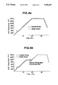
- FIG. 3a shows the temperature variation during the firing of the specimen 4, in which temperature differences between the inside and the outside of the shaped body are noted during temperature rise at two ranges of 200°-300° C. and 800°-900° C., and such temperature differences appear to be the cause of the cracks.
- the head quantity from the combustion at the burners was increased or decreased in response to the rise and fall of the body inside temperature, and the inside-outside temperature difference of the specimen 1 was minimized during the temperature rise as shown in FIG. 3b, and no cracks were generated in the specimen 1.
- Shaped bodies were prepared by mixing ceramic materials of talc, kaolin and alumina at a rate of cordierite composition, plasticizing the mixture through addition of glycerin as a molding aids and graphite as a pore-forming agent, molding the plasticized mixture, and drying. Separately, shaped bodies with saw dust therein as a pore-forming agent were also prepared.
- the shaped bodies were loaded in the shelves of the firing furnace 11 to fire them in the manner similar to that of Experiment 1 except the conditions of Table 3.
- the temperature was raised to a maximum temperature of 1,410° C. and the maximum temperature was kept for 10 hours. Then, it was cooled.
- the result of the above firing is shown in Table 3.
- the specimen 1 of the invention and specimen 4 of the prior art in this Experiment will be compared by referring to the data of Table 3.
- combustion control in response to the shaped body temperature was not effected, and its firing was finished after having a temperature difference between the inside and the outside of the shaped body at a range of 200°-320° C. during the temperature rise as shown in FIG. 4a.
- the heat quantity from the combustion at the burners was increased or decreased in response to the rise and fall of the body inside temperature, and the inside-outside temperature difference of the specimen 1 was minimized during the temperature rise as shown in FIG. 4b.
- the combustion of the pore-forming agent in the above-mentioned temperature range of 800°-900° C. perfect combustion was confirmed by keeping the burner combustion conditions constant while maintaining a constant rate of temperature rise or constant slope of the temperature rise curve.
- Rate of crack occurrence (%) was checked by visual inspection of the fired bodies after the above firing treatment. No cracks were found in the specimen of the invention.
- the burning degree of the pore-forming agent there was no residual of incompletely burnt pore-forming agent and the inside-outside difference of fine hole diameter was within 1-2 ⁇ m in the case of the specimens of the invention.
- heat quantity from burner means is increased or decreased in the temperature range for combustion of the molding aids or pore-forming agent, in response to the rise or fall of the inside temperature of the honeycomb body being fired, which inside temperature change is due to rapid combustion of such auxiliaries.
- the temperature at the outer portion of the honeycomb body is controlled, i.e., raised or lowered, so as to eliminate the inside-outside temperature difference. For instance, constant burner conditions are maintained until complete burn out of the pore-forming agent is confirmed, so as to prevent the occurrence of any cracks within and at outer portions of the honeycomb structure.
- the firing is effected in such a manner that the pore-forming agent is burnt uniformly throughout the honeycomb structure, from the inside to the outer portion thereof, so as to ensure stable production of high-quality fired products having fine holes whose diameters rae uniform through inside and outer portions of the products.
- the method of the invention is useful for firing ceramic honeycomb structures.
Landscapes
- Chemical & Material Sciences (AREA)
- Engineering & Computer Science (AREA)
- Ceramic Engineering (AREA)
- Inorganic Chemistry (AREA)
- Structural Engineering (AREA)
- Materials Engineering (AREA)
- Manufacturing & Machinery (AREA)
- Organic Chemistry (AREA)
- Life Sciences & Earth Sciences (AREA)
- Geology (AREA)
- Chemical Kinetics & Catalysis (AREA)
- Compositions Of Oxide Ceramics (AREA)
- Filtering Materials (AREA)
Abstract
A method for firing a ceramic honeycomb structure by a single furnace at a predetermined temperature in a predetermined atmosphere, while controlling combustion of a burner means for heating the ceramic honeycomb structure from the outside thereof. To this end, temperatures at the inside and outside portions of the ceramic honeycomb structure are detected, and the outside temperature thereof is regulated relative to the inside temperature thereof, based on the detected temperatures. The method ensures stable firing to produce a high-quality ceramic honeycomb structure, in which a pore-forming agent is uniformly burnt throughout the inside and outside of the product and the difference in the diameter of fine holes between those inside and those outside thereof is minimized so as to eliminate occurrence of cracks within and at end portions of the ceramic honeycomb structure.
Description
This is a continuation of application Ser. No. 07/744,683 filed Aug. 9, 191, now abandoned, which in turn is a continuation of application Ser. No. 07/397,465 filed as PCT/JP89/00191, Feb. 23, 1989, now abandoned.
This invention relates to a method which is suitable for firing a ceramic honeycomb structure.
Heretofore, a ceramic product of honeycomb shape, or a ceramic honeycomb structure, has been made by preparing a ceramic green body through mixing of ceramic materials with a molding aids and a pore-forming agent, molding the body into a honeycomb-shaped ceramic green body through extrusion of the mixed body, and finally firing the honeycomb-shaped ceramic green body in a firing furnace at a predetermined temperature.
The molding aids to be mixed with the ceramic materials for the above firing of the honeycomb structure are for instance an organic binder, such as methyl cellulose, carboxymethylcellulose, polyvinyl alcohol, starch paste, flour, glycerin, and the like or a surface active agent, or wax, etc. The above pore-forming agent to be used with the ceramic materials is for instance graphite, saw dust, starch etc. Such molding aids and pore-forming agent have the following special properties; namely, the molding aids or pore-forming agent is hard to heat from the outside of the honeycomb structure, but once ignited, burns rapidly and generates heat (the igniting temperature varies depending on the kind of auxiliary). Thus, the rapid burning of the molding aids or pore-forming agent results in uneven temperature distribution in the structure and tends to cause cracks within or at end portions of the final ceramic honeycomb structure.
To prevent the occurrence of cracks, it has been practiced to use a slow rate when raising the temperature of the body being fired, so as to suppress rapid heat generation within it. However, the oxygen concentration in the firing atmosphere at a temperature in ignition ranges of the molding aids or pore-forming agent varies depending on fluctuation of the weight of ceramic green body loaded in the furnace (to be referred to as "the loaded weight", hereinafter). Hence, the manner in which the molding aids or pore-forming agent within the ceramic honeycomb body burns varies, so that the temperature difference between the inside and outer portions of the ceramic honeycomb body becomes large or small. In consequence, sometimes cracks generate but sometimes not, resulting in a problem that the quality of the product is not uniform and stable production is hard to realize.
In the firing process, the pore-forming agent comes in contact with oxygen of the firing atmosphere and burns out in a certain time period, so as to produce fine holes of a desired diameter. It has been a practice to terminate the firing process with a certain time relationship with the timing of the burn out of the pore-forming agent. However, when the above-mentioned cracks are generated, even if the loaded weight is the same at the temperature range for burning the pore-forming agent, the oxygen concentration in the firing atmosphere varies and the kind of pore-forming agent varies, so that the burning characteristics of the pore-forming agent changes. Hence, it has been experienced in actual production that a pore-forming agent within the ceramic honeycomb body sometimes burns out but sometimes not, and there is a problem that stable production of fired goods with uniform distribution of fine holes having a desired diameter throughout the inside and outer portions thereof is difficult to attain.
Therefore, an object of the present invention is to solve the above-mentioned problems of the prior art by providing an improved method of firing ceramic honeycomb structures which ensures stable production of a high-quality product.
An object of the invention is to provide a method of firing a ceramic honeycomb structure at a predetermined temperature in a predetermined atmosphere, characterized in that temperatures at inside and outside portions of the ceramic honeycomb structure are detected by a temperature sensing means, and combustion of burner means is controlled based on the temperatures thus detected.
In the method of the invention, the temperatures at the inside and outside portions of the ceramic honeycomb structure are detected, and based on the detected temperatures, the outside temperature is controlled relative to the inside temperature by regulating the combustion of a burner means which heats the ceramic honeycomb structure from the outside thereof. For instance, when the inside temperature becomes higher than the outside temperature due to rapid combustion of the molding aids or the pore-forming agent, the heat supply from the burner means will be increased so as to raise the outside temperature to a level corresponding to the inside temperature. Sometimes, the heat supply from the burner means will be decreased so as to suppress the outside temperature. With such control, stable firing is ensured even when the temperature difference between the inside and outside of the shaped body varies due to fluctuation of the loaded weight of shaped bodies and due to changes in the conditions of the molding aids and/or pore-forming agent.
Referring to FIG. 5, when perfect combustion of the pore-forming agent is reached, the outside temperature of the body being fired coincides with the inside temperature thereof. The combustion of a burner means is controlled while detecting and monitoring the inside and outside temperatures until the above temperature coincidence is reached, for instance by keeping constant combustion in the vicinity of the above coincidence. With such control, stable firing can be effected even when the burning characteristics of the pore-forming agent varies due to fluctuation in the loaded weight of shaped bodies or due to change in the state of the pore-forming agent, and such stable firing enables production of high-quality goods.
FIG. 1 is a sectional view of a firing furnace to be used for working the firing method according to the present invention;
FIG. 2a through FIG. 4b are graphs showing temperature variations at the inside and outside portions of specimens of shaped body when such specimens were heated in the ensuing Experiments 1 through 3, covering both the method of the invention and a conventional method; and
FIG. 5 is a graph showing how the burn out of a pore-forming agent is reflected in the temperature change of a shaped body being fired.
Throughout different views of the drawings, the following symbols are used.
______________________________________ 10 a shaped body 11 a firing furnace 12 a truck 13 a shelf 14 a burner 15 a shelf board 16 a flame interrupting board 17 athermocouple 18 an oxygen sensor 19 ahole 20 anexhaust blower 21 an exhaust passage ______________________________________
Before firing a ceramic honeycomb structure by the method of the invention, a shaped body is prepared at first by mixing ceramic materials of a desired grain size, making a plastic batch by adding molding aids and/or a pore-forming agent to the mixture so as to plasticize the mixture, molding the plastic batch into a shaped body of honeycomb form through extrusion, and then drying the extruded body. A desired ceramic honeycomb structure can be obtained by firing the above shaped body by the method of the invention; namely, by firing the shaped body, while detecting the temperatures at the inside and outside of the shaped body, so as to control the combustion of a burner means, which heats the ceramic honeycomb structure from the outside thereof, in such a manner that the outside temperature of the shaped body is regulated to a level corresponding to the inside temperature thereof.
In carrying out the above firing, at least two thermocouples are applied to the specific shaped body, one inside and one outside thereof, so as to measure the temperature difference between the inside and outside portions. The thermocouples measure the temperature difference between the inside and outside portions (inside-outside temperature difference) of the honeycomb structure. In the temperature range wherein the molding aids or pore-forming agent burns, the above inside-outside temperature difference is generally large due to heat generation from such burning aids unless it is fully burnt out. Area having such inside-outside temperature difference is detected, and the combustion of a burner means is controlled at the detected area until the complete burn out of the pore-forming agent (coincidence of the inside temperature with the outside temperature) is reached. Preferably, the oxygen concentration in the firing atmosphere is kept at an excessive state, because it is hard for the pore-forming agent contained within the inside of the honeycomb shaped body to come into contact with oxygen of the firing atmosphere, and it is hard to ignite and to burn out such aids unless excessive oxygen is available.
Suitable molding aids can be selected, depending on the use, from the group consisting of an organic binder, such as methyl cellulose, carboxymethylcellulose, polyvinyl alcohol, starch paste, flour, glycerin, and the like, a surface active agent, wax, etc. A suitable pore-forming agent can be selected from the group consisting of graphite, saw dust, starch etc.
Shaped bodies 10 were prepared by weighing and mixing ceramic materials of kaolin and alumina to produce a mixture of mullite composition, plasticizing the mixture by adding methyl cellulose as a molding aid, molding the plasticized mixture, and drying. Separately, shaped bodies with flour added therein as a molding aid also were prepared.
The shaped bodies 10 were loaded in a firing furnace 11 by placing them on shelves 13 carried by a mobile truck 12 in the furnace. The loading was effected at the loaded weights of Table 1 and the shaped bodies 10 were heated with a mean temperature rise rate of the same table. The temperature was increased by combustion at burners 14 buried in opposite sidewalls of the furnace 11. To prevent flames of the burners 14 from coming in direct contact with the shaped bodies 10 or the ceramic honeycomb structures, flame interrupting boards 16 were disposed between outside posts of the shelves 13, which interrupting boards 16 were solid members made of mullite-mixed body. Shelf boards 15 were placed at the bottom and top of the shelves 13. Two thermocouples 17 were applied to one of the shaped bodies 10 placed in the firing furnace 11, one at the inside portion and one at the outside portion thereof. To measure the oxygen concentration of the firing atmosphere in the furnace 11, the active portion of an oxygen sensor 18 was disposed within the firing furnace 11 and it was connected to the outside through the sidewall of the furnace.
To allow the firing atmosphere to reach the inside of the shaped bodies 10, holes 19 were bored through each of the shelf boards 15 at portions facing the shaped bodies 10. Such holes 19 were found to be preferable. To minimize the inside-outside temperature difference of each shaped body 10, an exhaust passage 21 was formed through the truck 12 and the bottom wall of the furnace 11, and an exhaust blower 20 was installed at the outer end of the exhaust passage 21, so as to make the firing atmosphere flow through the inside of the shaped bodies 10.
The firing temperature was raised to a maximum temperature of 1,400° C. and the maximum temperature was kept for 2.5 hours. Then it was cooled at a rate of 150° C./hour.
The result of the above firing is shown in Table 1.
As can be seen from the data of Table 1 on both the specimen 1 of the invention and specimen 4 of the prior art, the specimen 4 without the burner combustion control in response to the shaped body temperature had cracks generated therein, but the specimen 1 of the invention with the above burner combustion control was free from cracks. FIG. 2a shows the temperature variation during the firing of the specimen 4, and one can note a temperature difference between the inside and the outside portions of the shaped body in a temperature range of 200°-300° C. due to the burning heat of the molding aids. Such temperature difference appears to be the cause of the cracks. On the other hand, in the case of the specimen 1 of the invention, the combustion of the burners was controlled in response to the rise and fall of the body inside temperature, and the inside-outside temperature difference of the shaped body was minimized as shown in FIG. 2b, and no cracks were generated in the specimen 1.
                                  TABLE 1
__________________________________________________________________________
                          Specimen
                          Invention               Prior art
Item                      1       2       3       4
__________________________________________________________________________
Fired body composition    mullite mullite mullite mullite
Material                  ·kaolin
                                  ·kaolin
                                          ·kaolin
                                                  ·kaolin
                          ·alumina
                                  ·alumina
                                          ·alumina
                                                  ·alumina
Molding auxiliary         methylcellulose
                                  methylcellulose
                                          flour   methylcellulose
Hole-making auxiliary     none    none    none    none
Loaded weight (kg)        300     100     300     300
Mean temperature rise rate (°C./hr)
                           50      30      50      50
Body inside-
         at burning of molding auxiliary
                          100     180     200     100
outside  at burning of hole-making auxiliary
                          --      --      --      --
temperature
difference (°C.)
Oxygen (O.sub.2)
         at burning of molding auxiliary
                           18     120      17      18
concentration (%)
         at burning of hole-making auxiliary
                          --      --      --      --
Control in response to rise and fall of body inside
                          done    done    done    no
temperature
Confirmation of complete burning out of hole-making
                          --      --      --      --
auxiliary
Rate of crack occurrence (%)
                           0       0       0        68
Burning degree
         inside residual of partly burnt
                          --      --      --      --
of hole-making
         stuff
auxiliary
         inside-outside difference of fine
                          --      --      --      --
         hole diameter (μm)
Overall appraisal         good    good    good    not good
__________________________________________________________________________
Shaped bodies were prepared by mixing ceramic materials of talc, kaolin and alumina at a rate of cordierite composition, plasticizing the mixture through addition of starch paste as a molding aids and saw dust as a pore-forming agent, molding the plasticized mixture, and drying. Separately, shaped bodies with graphite added therein as a pore-forming agent were also prepared.
The shaped bodies were loaded in the shelves of the firing furnace 11 to fire them in the manner similar to that of Experiment 1 except the conditions of Table 2. The temperature was raised to a maximum temperature of 1,350° C. and the maximum temperature was kept for 6 hours. Then, it was cooled. The result of the above firing is shown in Table 2.
As can be seen from the data of Table 4 on the specimen 1 of the invention and specimen 4 of the prior art of this Experiment, the specimen 4 without the burner combustion control in response to the shaped body temperature had a crack occurrence rate of 60%, but the specimen 1 of the invention with the above burner combustion control was free from cracks. FIG. 3a shows the temperature variation during the firing of the specimen 4, in which temperature differences between the inside and the outside of the shaped body are noted during temperature rise at two ranges of 200°-300° C. and 800°-900° C., and such temperature differences appear to be the cause of the cracks. On the other hand, in the case of the specimen 1 of the invention, the head quantity from the combustion at the burners was increased or decreased in response to the rise and fall of the body inside temperature, and the inside-outside temperature difference of the specimen 1 was minimized during the temperature rise as shown in FIG. 3b, and no cracks were generated in the specimen 1.
                                  TABLE 2
__________________________________________________________________________
                          Specimen
                          Invention         Prior art
Item                      1     2     3     4
__________________________________________________________________________
Fired body composition    cordierite
                                cordierite
                                      cordierite
                                            cordierite
Material                  ·talc
                                ·talc
                                      ·talc
                                            ·talc
                          ·kaolin
                                ·kaolin
                                      ·kaolin
                                            ·kaolin
                          ·alumina
                                ·alumina
                                      ·alumina
                                            ·alumina
Molding auxiliary         starch paste
                                starch paste
                                      starch paste
                                            starch paste
Hole-making auxiliary     saw dust
                                saw dust
                                      saw dust
                                            saw dust
Loaded weight (kg)        300   150   300   300
Mean temperature rise rate (°C./hr)
                          60    50    60    60
Body inside-
         at burning of molding auxiliary
                          90    120   90    90
outside  at burning of hole-making auxiliary
                          80    100   10    80
temperature
difference (°C.)
Oxygen (O.sub.2)
         at burning of molding auxiliary
                          19    20    19    19
concentration (%)
         at burning of hole-making auxiliary
                          12    15     8    12
Control in response to rise and fall of body inside
                          done  done  done  no
temperature
Confirmation of complete burning out of hole-making
                          --    --    done  no
auxiliary
Rate of crack occurrence (%)
                           0     0     0    60
Burning degree
         inside residual of partly burnt
                          none  none  none  none
of hole-making
         stuff
auxiliary
         inside-outside difference of fine
                           0     0      0.5  0
         hole diameter (μm)
Overall appraisal         good  good  good  not good
__________________________________________________________________________
Shaped bodies were prepared by mixing ceramic materials of talc, kaolin and alumina at a rate of cordierite composition, plasticizing the mixture through addition of glycerin as a molding aids and graphite as a pore-forming agent, molding the plasticized mixture, and drying. Separately, shaped bodies with saw dust therein as a pore-forming agent were also prepared.
The shaped bodies were loaded in the shelves of the firing furnace 11 to fire them in the manner similar to that of Experiment 1 except the conditions of Table 3. The temperature was raised to a maximum temperature of 1,410° C. and the maximum temperature was kept for 10 hours. Then, it was cooled. The result of the above firing is shown in Table 3.
The specimen 1 of the invention and specimen 4 of the prior art in this Experiment will be compared by referring to the data of Table 3. With the specimen 4, combustion control in response to the shaped body temperature was not effected, and its firing was finished after having a temperature difference between the inside and the outside of the shaped body at a range of 200°-320° C. during the temperature rise as shown in FIG. 4a. Checking of the product after the firing indicated cracks generated and the presence of residual of incompletely burnt pore-forming agent inside the body. Measurement of the diameters of fines holes at the inside and the outer portion of the fired body showed that it was 5 μm at the inside and 15 μm at the outer portion.
                                  TABLE 3
__________________________________________________________________________
                          Specimen
                          Invention         Prior art
Item                      1     2     3     4
__________________________________________________________________________
Fired body composition    cordierite
                                cordierite
                                      cordierite
                                            cordierite
Material                  ·talc
                                ·talc
                                      ·talc
                                            ·talc
                          ·kaolin
                                ·kaolin
                                      ·kaolin
                                            ·kaolin
                          ·alumina
                                ·alumina
                                      ·alumina
                                            ·alumina
Molding auxiliary         glycerin
                                glycerin
                                      glycerin
                                            glycerin
Hole-making auxiliary     graphite
                                graphite
                                      saw dust
                                            graphite
Loaded weight (kg)        600   1,000 600   600
Mean temperature rise rate (°C./hr)
                          70    70    70    70
Body inside-
         at burning of molding auxiliary
                          80    100   80    80
outside  at burning of hole-making auxiliary
                          10     5    80    10
temperature
difference (°C.)
Oxygen (O.sub.2)
         at burning of molding auxiliary
                          15    16    15    15
concentration (%)
         at burning of hole-making auxiliary
                           8     5    12     8
Control in response to rise and fall of body inside
                          done  done  done  no
temperature
Confirmation of complete burning out of hole-making
                          done  done  done  no
auxiliary
Rate of crack occurrence (%)
                           0     0     0    40
Burning degree
         inside residual of partly burnt
                          none  none  none  present
of hole-making
         stuff
auxiliary
         inside-outside difference of fine
                           2     1     0    10
         hole diameter (μm)
Overall appraisal         good  good  good  not good
__________________________________________________________________________
On the other hand, in the case of the specimen 1 of the invention, the heat quantity from the combustion at the burners was increased or decreased in response to the rise and fall of the body inside temperature, and the inside-outside temperature difference of the specimen 1 was minimized during the temperature rise as shown in FIG. 4b. As to the combustion of the pore-forming agent in the above-mentioned temperature range of 800°-900° C., perfect combustion was confirmed by keeping the burner combustion conditions constant while maintaining a constant rate of temperature rise or constant slope of the temperature rise curve.
Rate of crack occurrence (%) was checked by visual inspection of the fired bodies after the above firing treatment. No cracks were found in the specimen of the invention. As to the burning degree of the pore-forming agent, there was no residual of incompletely burnt pore-forming agent and the inside-outside difference of fine hole diameter was within 1-2 μm in the case of the specimens of the invention.
The invention is not restricted to the foregoing processing of the specimens and examples described above, and numerous modifications and changes are possible without departing from the scope of the ensuing claim.
As apparent from the detailed description in the foregoing, with the method of firing ceramic honeycomb structures according to the invention, heat quantity from burner means is increased or decreased in the temperature range for combustion of the molding aids or pore-forming agent, in response to the rise or fall of the inside temperature of the honeycomb body being fired, which inside temperature change is due to rapid combustion of such auxiliaries. Hence, the temperature at the outer portion of the honeycomb body is controlled, i.e., raised or lowered, so as to eliminate the inside-outside temperature difference. For instance, constant burner conditions are maintained until complete burn out of the pore-forming agent is confirmed, so as to prevent the occurrence of any cracks within and at outer portions of the honeycomb structure. Further, the firing is effected in such a manner that the pore-forming agent is burnt uniformly throughout the honeycomb structure, from the inside to the outer portion thereof, so as to ensure stable production of high-quality fired products having fine holes whose diameters rae uniform through inside and outer portions of the products. In short, the method of the invention is useful for firing ceramic honeycomb structures.
e, and numerous modifications and changes are possible without departing from the scope of the ensuing claim.
As apparent from the detailed description in the foregoing, with the method of firing ceramic honeycomb structures according to the invention, heat quantity from burner means is increased or decreased in the temperature range for combustion of the molding aids or pore-forming agent, in response to the rise or fall of the inside temperature of the honeycomb body being fired, which inside temperature change is due to rapid combustion of such auxiliaries. Hence, the temperature at the outer portion of the honeycomb body is controlled, i.e., raised or lowered, so as to eliminate the inside-outside temperature difference. For instance, constant burner conditions are maintained until complete burn out of the pore-forming agent is confirmed, so as to prevent the occurrence of any cracks within and at outer portions of the honeycomb structure. Further, the firing is effected in such a manner that the pore-forming agent is burnt uniformly throughout the honeycomb structure, from the inside to the outer portion thereof, so as to ensure stable production of high-quality fired products having fine holes whose diameters rae uniform through inside and outer portions of the products. In short, the method of the invention is useful for firing ceramic honeycomb structures.
Claims (3)
1. A method of firing a ceramic honeycomb structure containing organic additives, said method comprising the steps of:
placing a first thermocouple inside the ceramic honeycomb structural body, and placing a second thermocouple directly adjacent to and outside the ceramic honeycomb structural body to detect temperatures at inside and outside portions of the ceramic honeycomb structural body;
detecting a differential temperature condition between said inside and outside portions of said ceramic honeycomb structure, said differential temperature condition resulting from non-uniform combustion of said organic additives at inside and outside portions of said ceramic honeycomb structure; and
controlling combustion of burner means based on the detected differential temperature condition.
2. The method of claim 1, wherein said first thermocouple is provided in a through hole formed in said ceramic honeycomb structure.
3. The method of claim 1, wherein said combustion of burner means is controlled so as to maintain temperatures at said inside and outside portions of the ceramic honeycomb structure substantially constant.
Priority Applications (1)
| Application Number | Priority Date | Filing Date | Title |
|---|---|---|---|
| US07/952,150 US5256347A (en) | 1988-02-25 | 1992-09-28 | Method of firing ceramic honeycomb structure |
Applications Claiming Priority (5)
| Application Number | Priority Date | Filing Date | Title |
|---|---|---|---|
| JP63-40599 | 1988-02-25 | ||
| JP63040599A JPH01215765A (en) | 1988-02-25 | 1988-02-25 | Calcination of ceramic honeycomb structure |
| US39746589A | 1989-08-18 | 1989-08-18 | |
| US74468391A | 1991-08-09 | 1991-08-09 | |
| US07/952,150 US5256347A (en) | 1988-02-25 | 1992-09-28 | Method of firing ceramic honeycomb structure |
Related Parent Applications (1)
| Application Number | Title | Priority Date | Filing Date |
|---|---|---|---|
| US74468391A Continuation | 1988-02-25 | 1991-08-09 |
Publications (1)
| Publication Number | Publication Date |
|---|---|
| US5256347A true US5256347A (en) | 1993-10-26 |
Family
ID=27460920
Family Applications (1)
| Application Number | Title | Priority Date | Filing Date |
|---|---|---|---|
| US07/952,150 Expired - Fee Related US5256347A (en) | 1988-02-25 | 1992-09-28 | Method of firing ceramic honeycomb structure |
Country Status (1)
| Country | Link |
|---|---|
| US (1) | US5256347A (en) |
Cited By (21)
| Publication number | Priority date | Publication date | Assignee | Title |
|---|---|---|---|---|
| US6183845B1 (en) * | 1997-11-12 | 2001-02-06 | Banner Pharmacaps, Inc. | Multiple layer softgel |
| WO2001063194A1 (en) * | 2000-02-22 | 2001-08-30 | Corning Incorporated | Method for controlling the firing of ceramics |
| US20020050669A1 (en) * | 1998-09-29 | 2002-05-02 | Takasi Obata | Production process of a hexagonal honeycomb structure |
| US20030151155A1 (en) * | 2002-01-21 | 2003-08-14 | Ngk Insulators, Ltd. | Method for manufacturing a porous ceramic structure |
| EP1042250A4 (en) * | 1997-12-02 | 2004-04-28 | Corning Inc | Method for firing ceramic honeycomb bodies |
| EP1036048A4 (en) * | 1997-12-02 | 2004-05-06 | Corning Inc | HONEYCOMB CERAMIC BODY COOKING PROCESS |
| US20050046063A1 (en) * | 2002-01-21 | 2005-03-03 | Ngk Insulators, Ltd. | Method for manufacturing a porous ceramic structure |
| US20050056974A1 (en) * | 2003-08-01 | 2005-03-17 | Asahi Glass Company, Limited | Firing container for silicon nitride ceramics |
| US20050253311A1 (en) * | 2003-01-07 | 2005-11-17 | Ngk Insulators, Ltd. | Method of baking ceramic honeycomb structure |
| WO2006048003A1 (en) * | 2004-11-03 | 2006-05-11 | Ctb Ceramic Technology Gmbh | Method and device for accelerated burning of porous ceramic moulded parts |
| US20070006561A1 (en) * | 2005-05-31 | 2007-01-11 | Brady Michael D | Aluminum titanate ceramic forming batch mixtures and green bodies including pore former combinations and methods of manufacturing and firing same |
| US20080300127A1 (en) * | 2007-05-31 | 2008-12-04 | David Lambie Tennent | Aluminum titanate ceramic forming batch mixtures and green bodies with pore former |
| US20090298670A1 (en) * | 2008-05-27 | 2009-12-03 | Martin Joseph Murtagh | Method for removing graphite from cordierite bodies |
| US20100130352A1 (en) * | 2008-11-25 | 2010-05-27 | Dabich Ii Leonard Charles | Methods For Processing Shaped Bodies |
| US20130049269A1 (en) * | 2010-05-17 | 2013-02-28 | Sumitomo Chemical Company, Limited | Method for manufacturing ceramic honeycomb fired body |
| US20150050609A1 (en) * | 2013-08-15 | 2015-02-19 | Corning Incorparated | Method and apparatus for thermally debindering a cellular ceramic green body |
| US9126869B1 (en) * | 2013-03-15 | 2015-09-08 | Ibiden Co., Ltd. | Method for manufacturing aluminum-titanate-based ceramic honeycomb structure |
| US10022891B2 (en) * | 2015-02-24 | 2018-07-17 | Ngk Insulators, Ltd. | Manufacturing method of honeycomb structure, and honeycomb formed body |
| US10035283B2 (en) * | 2015-02-24 | 2018-07-31 | Ngk Insulators, Ltd. | Manufacturing method of honeycomb structure and honeycomb formed body |
| CN110041082A (en) * | 2018-01-15 | 2019-07-23 | 日本碍子株式会社 | The manufacturing method of ceramic firing body and the process for calcining of ceramic mouldings |
| US10549074B2 (en) | 2005-01-13 | 2020-02-04 | Avent, Inc. | Tubing assembly and signal generation placement device and method for use with catheter guidance systems |
Citations (10)
| Publication number | Priority date | Publication date | Assignee | Title |
|---|---|---|---|---|
| US3932310A (en) * | 1974-03-07 | 1976-01-13 | W. R. Grace & Co. | Reduction firing of ceramics composited with organic binders |
| US4055614A (en) * | 1973-07-24 | 1977-10-25 | Ngk Spark Plug Co., Ltd. | Method of firing formed ceramic body |
| JPS54138005A (en) * | 1978-04-19 | 1979-10-26 | Ngk Spark Plug Co | Manufacture of honeycomb structure body made of gammaaal203 |
| JPS55144474A (en) * | 1979-04-24 | 1980-11-11 | Tdk Electronics Co Ltd | Burning method |
| GB2112318A (en) * | 1981-12-22 | 1983-07-20 | Wienerberger Baustoffind Ag | Process and apparatus for the production of articles consisting of ceramic material |
| US4550005A (en) * | 1983-09-24 | 1985-10-29 | Ngk Insulators, Ltd. | Extrusion die for ceramic honeycomb structure |
| US4680153A (en) * | 1983-05-27 | 1987-07-14 | Institut For Energetik - Zentralstelle Fur Rationelle Energieanwendung | Process for manufacturing highly porous mineralic bodies of polymorphic structure |
| US4795598A (en) * | 1986-12-05 | 1989-01-03 | Solid Micron Materials, Pte, Ltd. | Method of making articles from sinterable materials |
| EP0357789A1 (en) * | 1988-02-10 | 1990-03-14 | Ngk Insulators, Ltd. | Process of producing a ceramic honeycomb structural body |
| US4927577A (en) * | 1987-02-27 | 1990-05-22 | Ngk Insulators, Ltd. | Process for firing ceramic honeycomb structural bodies |
-
1992
- 1992-09-28 US US07/952,150 patent/US5256347A/en not_active Expired - Fee Related
Patent Citations (10)
| Publication number | Priority date | Publication date | Assignee | Title |
|---|---|---|---|---|
| US4055614A (en) * | 1973-07-24 | 1977-10-25 | Ngk Spark Plug Co., Ltd. | Method of firing formed ceramic body |
| US3932310A (en) * | 1974-03-07 | 1976-01-13 | W. R. Grace & Co. | Reduction firing of ceramics composited with organic binders |
| JPS54138005A (en) * | 1978-04-19 | 1979-10-26 | Ngk Spark Plug Co | Manufacture of honeycomb structure body made of gammaaal203 |
| JPS55144474A (en) * | 1979-04-24 | 1980-11-11 | Tdk Electronics Co Ltd | Burning method |
| GB2112318A (en) * | 1981-12-22 | 1983-07-20 | Wienerberger Baustoffind Ag | Process and apparatus for the production of articles consisting of ceramic material |
| US4680153A (en) * | 1983-05-27 | 1987-07-14 | Institut For Energetik - Zentralstelle Fur Rationelle Energieanwendung | Process for manufacturing highly porous mineralic bodies of polymorphic structure |
| US4550005A (en) * | 1983-09-24 | 1985-10-29 | Ngk Insulators, Ltd. | Extrusion die for ceramic honeycomb structure |
| US4795598A (en) * | 1986-12-05 | 1989-01-03 | Solid Micron Materials, Pte, Ltd. | Method of making articles from sinterable materials |
| US4927577A (en) * | 1987-02-27 | 1990-05-22 | Ngk Insulators, Ltd. | Process for firing ceramic honeycomb structural bodies |
| EP0357789A1 (en) * | 1988-02-10 | 1990-03-14 | Ngk Insulators, Ltd. | Process of producing a ceramic honeycomb structural body |
Non-Patent Citations (2)
| Title |
|---|
| McFadden et al., The Jet Burner A New Concept in Fast Precision Firing, Ceramic Bulletin, pp. 160 164, vol. 41, No. 3, 1962. * |
| McFadden et al., The Jet Burner-A New Concept in Fast Precision Firing, Ceramic Bulletin, pp. 160-164, vol. 41, No. 3, 1962. |
Cited By (35)
| Publication number | Priority date | Publication date | Assignee | Title |
|---|---|---|---|---|
| US6183845B1 (en) * | 1997-11-12 | 2001-02-06 | Banner Pharmacaps, Inc. | Multiple layer softgel |
| EP1042250A4 (en) * | 1997-12-02 | 2004-04-28 | Corning Inc | Method for firing ceramic honeycomb bodies |
| EP1036048A4 (en) * | 1997-12-02 | 2004-05-06 | Corning Inc | HONEYCOMB CERAMIC BODY COOKING PROCESS |
| US20020050669A1 (en) * | 1998-09-29 | 2002-05-02 | Takasi Obata | Production process of a hexagonal honeycomb structure |
| WO2001063194A1 (en) * | 2000-02-22 | 2001-08-30 | Corning Incorporated | Method for controlling the firing of ceramics |
| US6511628B2 (en) | 2000-02-22 | 2003-01-28 | Corning Incorporated | Method for controlling the firing of ceramics |
| US20030151155A1 (en) * | 2002-01-21 | 2003-08-14 | Ngk Insulators, Ltd. | Method for manufacturing a porous ceramic structure |
| US20050046063A1 (en) * | 2002-01-21 | 2005-03-03 | Ngk Insulators, Ltd. | Method for manufacturing a porous ceramic structure |
| BE1017933A3 (en) * | 2002-01-21 | 2009-12-01 | Ngk Insulators Ltd | PROCESS FOR PRODUCING A POROUS CERAMIC STRUCTURE |
| US7429351B2 (en) | 2002-01-21 | 2008-09-30 | Ngk Insulators, Ltd. | Method for manufacturing a porous ceramic structure |
| EP1591428A4 (en) * | 2003-01-07 | 2008-04-16 | Ngk Insulators Ltd | Method of baking ceramic honeycomb structure |
| US20050253311A1 (en) * | 2003-01-07 | 2005-11-17 | Ngk Insulators, Ltd. | Method of baking ceramic honeycomb structure |
| US20050056974A1 (en) * | 2003-08-01 | 2005-03-17 | Asahi Glass Company, Limited | Firing container for silicon nitride ceramics |
| US7335019B2 (en) * | 2003-08-01 | 2008-02-26 | Asahi Glass Company, Limited | Firing container for silicon nitride ceramics |
| WO2006048003A1 (en) * | 2004-11-03 | 2006-05-11 | Ctb Ceramic Technology Gmbh | Method and device for accelerated burning of porous ceramic moulded parts |
| US10549074B2 (en) | 2005-01-13 | 2020-02-04 | Avent, Inc. | Tubing assembly and signal generation placement device and method for use with catheter guidance systems |
| CN101213156B (en) * | 2005-05-31 | 2014-07-16 | 康宁股份有限公司 | Aluminum titanate ceramic forming batch mixtures and green bodies including pore former combinations and methods of manufacturing and firing same |
| US20070006561A1 (en) * | 2005-05-31 | 2007-01-11 | Brady Michael D | Aluminum titanate ceramic forming batch mixtures and green bodies including pore former combinations and methods of manufacturing and firing same |
| US7976768B2 (en) * | 2005-05-31 | 2011-07-12 | Corning Incorporated | Aluminum titanate ceramic forming batch mixtures and green bodies including pore former combinations and methods of manufacturing and firing same |
| US20110195838A1 (en) * | 2005-05-31 | 2011-08-11 | Michael Donavon Brady | Aluminum titanate ceramic forming batch mixtures and green bodies including pore former combinations and methods of manufacturing and firing same |
| US20080300127A1 (en) * | 2007-05-31 | 2008-12-04 | David Lambie Tennent | Aluminum titanate ceramic forming batch mixtures and green bodies with pore former |
| US7977266B2 (en) | 2007-05-31 | 2011-07-12 | Corning Incorporated | Aluminum titanate ceramic forming batch mixtures and green bodies with pore former |
| US20090298670A1 (en) * | 2008-05-27 | 2009-12-03 | Martin Joseph Murtagh | Method for removing graphite from cordierite bodies |
| US20100130352A1 (en) * | 2008-11-25 | 2010-05-27 | Dabich Ii Leonard Charles | Methods For Processing Shaped Bodies |
| WO2010065337A1 (en) * | 2008-11-25 | 2010-06-10 | Corning Incorporated | Methods for processing shaped bodies |
| US20130049269A1 (en) * | 2010-05-17 | 2013-02-28 | Sumitomo Chemical Company, Limited | Method for manufacturing ceramic honeycomb fired body |
| US8926891B2 (en) * | 2010-05-17 | 2015-01-06 | Sumitomo Chemical Company, Limited | Method for manufacturing ceramic honeycomb fired body |
| US9561985B2 (en) * | 2010-05-17 | 2017-02-07 | Sumitomo Chemical Company, Limited | Method for manufacturing ceramic honeycomb fired body |
| US20130140747A1 (en) * | 2010-05-17 | 2013-06-06 | Sumitomo Chemical Company, Limited | Method for manufacturing ceramic honeycomb fired body |
| US9126869B1 (en) * | 2013-03-15 | 2015-09-08 | Ibiden Co., Ltd. | Method for manufacturing aluminum-titanate-based ceramic honeycomb structure |
| US20150050609A1 (en) * | 2013-08-15 | 2015-02-19 | Corning Incorparated | Method and apparatus for thermally debindering a cellular ceramic green body |
| US10479734B2 (en) * | 2013-08-15 | 2019-11-19 | Corning Incorporated | Method and apparatus for thermally debindering a cellular ceramic green body |
| US10022891B2 (en) * | 2015-02-24 | 2018-07-17 | Ngk Insulators, Ltd. | Manufacturing method of honeycomb structure, and honeycomb formed body |
| US10035283B2 (en) * | 2015-02-24 | 2018-07-31 | Ngk Insulators, Ltd. | Manufacturing method of honeycomb structure and honeycomb formed body |
| CN110041082A (en) * | 2018-01-15 | 2019-07-23 | 日本碍子株式会社 | The manufacturing method of ceramic firing body and the process for calcining of ceramic mouldings |
Similar Documents
| Publication | Publication Date | Title |
|---|---|---|
| US5256347A (en) | Method of firing ceramic honeycomb structure | |
| JPH0745348B2 (en) | Firing method of ceramic honeycomb structure | |
| US6287509B1 (en) | Method for firing ceramic honeycomb bodies | |
| US6089860A (en) | Method for firing ceramic honeycomb bodies and a tunnel kiln used therefor | |
| EP1036048B2 (en) | Method for firing ceramic honeycomb bodies | |
| US7429351B2 (en) | Method for manufacturing a porous ceramic structure | |
| US20030151155A1 (en) | Method for manufacturing a porous ceramic structure | |
| EP0362400B1 (en) | Method of firing ceramic honeycomb structure | |
| EP0709638A2 (en) | Method and apparatus for firing ceramic formed bodies | |
| US6537481B2 (en) | Hybrid method for firing of ceramics | |
| KR20050030959A (en) | Method for producing porous ceramic article | |
| US6511628B2 (en) | Method for controlling the firing of ceramics | |
| DE68905018T2 (en) | METHOD FOR BURNING A CERAMIC HONEYCOMB STRUCTURE. | |
| EP3663688A1 (en) | Tunnel furnace for a baking process for ceramic materials | |
| JPH03158696A (en) | Kiln | |
| JP2001050671A (en) | Surface-scorching device for friction member | |
| US2444361A (en) | Refractory article | |
| JPH04222387A (en) | Continuous tunnel kiln | |
| JPS60137866A (en) | burner plate | |
| JPH0122125B2 (en) | ||
| JPH01114692A (en) | Ignition furnace for sintering machine | |
| JPS63238306A (en) | Rotary type burner | |
| JPS6246515B2 (en) | ||
| JPH02263089A (en) | Kiln | |
| JPH02183793A (en) | Drying control method and device for ladle |
Legal Events
| Date | Code | Title | Description |
|---|---|---|---|
| REMI | Maintenance fee reminder mailed | ||
| LAPS | Lapse for failure to pay maintenance fees | ||
| FP | Lapsed due to failure to pay maintenance fee |
Effective date: 19971029 |
|
| STCH | Information on status: patent discontinuation |
Free format text: PATENT EXPIRED DUE TO NONPAYMENT OF MAINTENANCE FEES UNDER 37 CFR 1.362 |