US525606A - Pneumatic dispatch system - Google Patents
Pneumatic dispatch system Download PDFInfo
- Publication number
- US525606A US525606A US525606DA US525606A US 525606 A US525606 A US 525606A US 525606D A US525606D A US 525606DA US 525606 A US525606 A US 525606A
- Authority
- US
- United States
- Prior art keywords
- tube
- carrier
- circuit
- chamber
- delivering
- Prior art date
- Legal status (The legal status is an assumption and is not a legal conclusion. Google has not performed a legal analysis and makes no representation as to the accuracy of the status listed.)
- Expired - Lifetime
Links
- 239000000969 carrier Substances 0.000 description 20
- 238000010276 construction Methods 0.000 description 10
- 230000005540 biological transmission Effects 0.000 description 5
- 239000000872 buffer Substances 0.000 description 1
- 230000001747 exhibiting effect Effects 0.000 description 1
- 230000005484 gravity Effects 0.000 description 1
- 238000005192 partition Methods 0.000 description 1
- 239000006187 pill Substances 0.000 description 1
- 108010085990 projectin Proteins 0.000 description 1
Images

Classifications
-
- B—PERFORMING OPERATIONS; TRANSPORTING
- B65—CONVEYING; PACKING; STORING; HANDLING THIN OR FILAMENTARY MATERIAL
- B65G—TRANSPORT OR STORAGE DEVICES, e.g. CONVEYORS FOR LOADING OR TIPPING, SHOP CONVEYOR SYSTEMS OR PNEUMATIC TUBE CONVEYORS
- B65G51/00—Conveying articles through pipes or tubes by fluid flow or pressure; Conveying articles over a flat surface, e.g. the base of a trough, by jets located in the surface
- B65G51/04—Conveying the articles in carriers having a cross-section approximating that of the pipe or tube; Tube mail systems
- B65G51/26—Stations
Definitions
- Tm mms mns co, moro-Lmn, wAsNmcmw, n. c.
- My invention relates to improvements in pneumatic dispatch or transit systems for from the tube-circuit without breaking or interrupting the continuity of the motive-power in the tube-circuit, and my present invention consists particularly in certain features of construction of the tube of the tube-circuit, carriers, and apparatus for delivering the carriers to and from the tube-circuit at the respective local or sub-stations, hereinafter described and pointed out in the claims.
- the primary object of my invention is to produce a pneumatic dispatch and transit system that is more convenient, and vastly more simple in construction, than the systems heretofore devised.
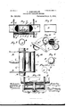
- Figure 1 is a diagrammatic plan, partly in section, of a system embodying my invention.
- Fig. 2 is a transverse section of a preferable form of tube for the tube-circuit.
- Fig. 3 is a top plan, partly in section, and
- Fig. 4 is a transverse vertical section on line 4-4, Fig. 3, of a suitable apparatus for delivering the carriers to and from the tube-circuit, at the local or substations, and suitable for use with the'form of tube shown in Fig. 2, and
- Fig. 5 is a vertical section on line 5-5, Figs. 8 and 4, exhibiting a partial central longitudinal section of a carrier in position in the carrier-delivering apparatus.
- Fig. 7 is a longitudinal vertical section of the receiving-end Fig. 6 isan end-view of a.
- Fig. 8 is an enlarged section on line 8-8, Fig. 1.
- Fig. 9 is a transverse section of a modified construction of tubing for the tubecircuit.
- Fig. 10 is a top plan of a construction of a local or sub-stations carrier-delivering apparatus suitable for use with the form of tube shown in Fig. 9, and
- Fig. 11 isA a vertical section on line 11-11, Fig. 10.
- Fig. 12 is a left hand side elevation Vrelative to Fig. 10.
- Fig. 13 is an end view of a carrier suitable for use with the construction shown in Figs. 9, l0, l1, 12 and 13.
- A represents the central or main station; B the tube-circuit, and C the local or sub-stations located along the tube-circuit.
- the tube-circuit leads from and returns to the central or main station, and is open at its receiving-end and provided with an outwardly opening valve b at its delivering-end, as shown in Fig. 1.
- the motive power is preferably obtained by means of a blower, or pump, D, suitably connected with the tube-circuit near the. delivering-end at the main station and adapted to exhaust the tube-circuit of air at the point of itsV connection with the tube-circuit and thereby create a pneumatic power through the tube-circuit, the tube or pipe CZ that connects the blower or pump with the tube-circuit being preferably closed at its junction with the tube-circuit, by a perforated diaphragm b3, as shown in Fig. 8.
- the tubing of the tube-circuit is square or angular in cross-section as'shown in Fig. 2, and the ends or heads e of the carriers E are correspondingly shaped and nicely but easily fit the conducting-tube, so that the carriers shall be properly guided in their transmission in the tube-circuit.
- the body of the carrier comprises a box or receptacle E that, in transverse section, is suiiiciently'smaller than the tube ofthe tubecircuit to enable the carrier to pass around curves, b', in the tube-circuit.
- Thebox or receptacle of the carrier at the ⁇ top, is provided with a lid or cover, E2, for access, and the heads or ends of the carrier are provided IOO with buffers, e', preferably of the semi-'spherivided with guides or ways, B', arranged transversely of the tube, and supporting the apparatus adapted to deliver the carrier containing the message, cash, parcel, or matter transmitted, to and from the tube-circuit, the end-pieces or members G of said delivering apparatus being adapted to reciprocate endwlse of said ways or guides.
- Said carrier-deliverin g apparatus has an open-ended chamber G for receiving the carrier and delivering the latter to and from the tube-circuit, said chamber, in cross-section, corresponding, in form and size, with the tubes of the tube-circuit and forming a part of the tube-circuit when brought into Y line with the tube-circuit.
- Said apparatus has another open-ended chamber, G2, arranged parallel with chamber G, corresponding in cross-section with the tube of the tube-circuit and forming a part of the tube-circuit when brought into line with the tube-circuit.
- chamber G3 is preferably provided between chambers G and G2 and the partition walls G4 between said chambers are preferably made as thin as possible.
- Chamber G3 is preferably closed at its ends, with the end-walls perforated, as at G5, Figs. 3 and 4, by which construction another carrier in transitis prevented from entering said chamber during the operation of the deliveringapparatus.
- Suitable means for holding orretaining the local station carrier-delivering apparatus with chamber G in line with the tube-circuit is provided, and consists, preferably, in a reciprocating locking-pin or bar, H, that fits within and is adapted to reciprocate endwise of a corresponding hole g in the downwardly enlargedportion g of the bottom-wallot chamber G', as shown in Figs. 4 and 5, said enlargement of the bottom wall of said chamber extending preferably the entire length or approximately the entire length of the chamber,
- Locking-pin or bar H does not occupy the entire length of hole g, but a'spring
- I is interposed and confined between the in- ⁇ ner end of said pin or bar and the adjacent end of hole g and acts in the direction to retain the locking-pin or bar in position with.
- the arrangement of parts is such that when a carrier is sent from the central or main station t0 the local or sub-station to which the carrier belongs, upon arrival of the carrier within ehamber G' of the carrier-delivering apparatus of said station, finger or key Kof the carrier will drop into recess g3, slide along the bottom of said recess until it engages toe orprojeotion H of locking-pin or bar H and thereupon f actuate the latter, against the action of spring I, to unlock the respective carrier-delivering apparatus subject to the action of a spring, L, adapted to actuate the carrier-delivering apparatus laterally of the tube-circuit to bring :f
- Finger or key K of the carrier being pivoted to the reduced portion or box or receptacle of the carrier, as shown,does not inrany wise, obstruct orinterfere with the transmis' Said finger or key mayf sion of the carrier. be operated by gravity, or by the action of a outside of casing m, is provided with a stop, 4
- the locking-mechanism might be located somewhat to one side of the central portion, as shown-at a in dotted lines, Figs. 4 and 6 in another station and carrier,
- the mechanism for arresting the carrier upon arriving in chamber G' of the delivering apparatus of its station shall, either in location, construction, or arrangement be unlike that of any other local or sub-station and carrier so that there shall be no liability of any carrier being stopped or arrested at any local or substation to which it does not belong.
- the carrier in placing the carrier into chamber G' of the apparatus for delivering the carrier to the tube-circuit, it should not be placed into said chamber in the same position in which it is taken therefrom, but should be so placed therein, end for'end, down-side up, or so as to bring finger or key K adjacent some other side of said chamber, orotherwise, so that it will not interfere with the transmission of the carrier when delivered to the tube-circuit.
- the tubing of the tube-circuit, at its receiving-end at the central or main station is somewhat graduallyenlarged downwardly, as at b2, to prevent finger or key K of the carriers from slipping in under the tube in entering the carriers.
- tube-circuit For the tube-circuit, I would not be understood as limiting myself to that form.
- said tube might be circular in cross-section, as Ishown in Fig. 9, with a rib or tongue, P, formed upon the internal surface thereof and adapted to engage a corresponding groove or recess, Q, (shown in Fig 13) in the carriers, and thereby properly guide the carriers in their transmission.
- an oscillating apparatus instead of Aa reciprocating spring-actuated apparatus for delivering the carrier to and from the tube-cir cuit, an oscillating apparatus might be employed, as shown in Figs.
- chambers G', G2, and G3 of the transmitting apparatus would be arranged in the form ofv an are as shown in Fig. 11,and the tube-circuit, at each local orvsubstation, would preferably be provided ⁇ with two segmental plates, R, located a suitable distance apart and suitably connected with, each other, as at R', and the carrier-delivering apparatus, at the central portion, would be provided with a gravity-lever, S, suitably fulcrumed, as at S', to said connecting member of the supporting segmental plates.
- the mechanism for arresting the carriers in case of a tube-circnit having a tubular cross-section, upon their arrival, from the main station, in chamber G' ofthe carrier-delivering-apparatus of the respective local station, would be substantially the same as that hereinbefore described, except that, perhaps, a spring VO for actuating linger or key E, would likely be employed in most cases.
- chamber G2 of the carrier-dellvering-apparatus is to avoid an interruption of theycontinuity of the tube-circuit when said apparatus is in position with the carrier-receiving -chamber G' ready to have the carrier put therein or taken therefrom by the attendant at the station with which said carrier is identified.
- the latter is located a suitable distance trom chamber G2, and hence, another chamber, G3, as-already indicated is provided between chambers G' and G2, the function of said additional chamber being to reduce, to aminimum,obstruction to the current of air through the tube-circuit in actuating ⁇ the Y carrier.
- said carrier-delivering apparatus comprising two open-ended chambers adapted to form a part of the tube-circuit, respectively, one of said chambers being adapted to deliver the respective carrier to and from the tube-circuit, and the other chamber being adapted to accommodate the transit of other carriers when the carrier-.delivering chamber is out of line with the tube-circuit, alockingpin or bar for locking the carrier-delivering .-apparatus in position with the carrier-delivering chamberin line with the tube-circuit; a finger or key connected with the carrier for engaging and actuating said bar or pin to unlock upon the reception of the carrier, during its transmissionv from the central or main station, by the carrier-delivering chamber of the carrier delivering apparatus, and thereby permitting said apparatus to be actuated to deliver the carrier from and bring the other chamber into line with the tube-circuit, substantially as set forth.
- a pneu matic dis patch-system the combination of a line of pneumatic tubing leading from and back to the main or central station, carriers for transmitting matter between the main station and local or sub-stations, suitable apparatus at the local or sub-stations fordelivering the carriers to and from the tube-circuit, said carrier delivering apparatus comprising two open-ended chambers adapted to form a.
- a reciprocating locking-pin or bar H for locking the carrier-delivering apparatus in position with the carrier-deliveringfchamber in line with the tube-circuit, and provided with a projecting toe or member H', suitable means acting to retain said locking pin or bar in its locking position, and a linger or key connected with the carrier for engaging said toe or proj ectin g member of the locking-pin or bar and actuating said bar or pin to unlock upon the reception of the carrier, during its transmission from the central orrmain station, by the carrier-delivering-chamber of the carrier-delivering-apparatus, substantially as set forth.
- a pneumatic dispatch system g'the combination of aline of pneumatic tubing leading from and back to the central or main station, carriers for transmitting matter between the main station and local or sub-stations, suitable apparatus at the local or substations for delivering the carriers to and from the tube-circuit and comprising ⁇ three chauibnuif arranged lthe one between the others and' other chambers being adapted to form a pd of the tube-circuit, respectively, one of .U outer chambers to be utilized vfor deliven.
- circuit andthe other outer chamber bein adapted to permit the transit of other uf riers when the carrier-delivering-chamberih out of line with the tube-circuit, the im vening chamber being adapted to avoiditmt break or interruption of the continuity of tlli ⁇ 'r motive power during the operation of the nl# rier-delivering apparatus, substantially i. set forth. 4.
Landscapes
- Physics & Mathematics (AREA)
- Engineering & Computer Science (AREA)
- Fluid Mechanics (AREA)
- Mechanical Engineering (AREA)
- Air Transport Of Granular Materials (AREA)
Description
(No Model.)
2 Sheets-Sheet 1.
0. KONIGSLOW. PNEUMATIG DISPATCH SYSTEM.
A w 9 n a l l I H 4 j l V Lb p nv s W/ r d e Lm. e. f t G a D.. G. III
Ihr' G. l.
Ulli i 'l :as cn. mcmmqmo. wnsnmmon, u a.
(No Medel.) 2 Sheets-Sheet 2.
' O. KONIGSLOW.
PNBUMATIG DISPATCH SYSTEM.
No. 525,606. Patented Sept. 4, 1894.v
Tm: mms mns co, moro-Lmn, wAsNmcmw, n. c.
wUNITED STATES PATENT OFFICE.
` OTTO KONIGSLOW, OF CLEVELAND, OHIO.
PNEUMATIC DISPATCH SYSTEM.
SPECIFICATION forming part of Letters Patent No. 525,606dated September 4, 1894.
Application filed umh 16,1893. serial No. 466,252. (No model.)
To a/ZZ wiz/0m it may concern:
Be it known that I, OTTO KoNIGsLoW, of Cleveland, in the county of Cuyahoga and State of Ohio, have invented certain new and useful Improvements in Pneumatic Dispatch Systems; and Ido hereby declare the following to be a full, clear, and exact description of the invention, such as will enable others skilledy in the art to which it pertains to make and use the same. Y
My invention relates to improvements in pneumatic dispatch or transit systems for from the tube-circuit without breaking or interrupting the continuity of the motive-power in the tube-circuit, and my present invention consists particularly in certain features of construction of the tube of the tube-circuit, carriers, and apparatus for delivering the carriers to and from the tube-circuit at the respective local or sub-stations, hereinafter described and pointed out in the claims.
The primary object of my invention is to produce a pneumatic dispatch and transit system that is more convenient, and vastly more simple in construction, than the systems heretofore devised. A
In the accompanying drawings, Figure 1 is a diagrammatic plan, partly in section, of a system embodying my invention. Fig. 2is a transverse section of a preferable form of tube for the tube-circuit. Fig. 3 is a top plan, partly in section, and Fig. 4 is a transverse vertical section on line 4-4, Fig. 3, of a suitable apparatus for delivering the carriers to and from the tube-circuit, at the local or substations, and suitable for use with the'form of tube shown in Fig. 2, and Fig. 5 is a vertical section on line 5-5, Figs. 8 and 4, exhibiting a partial central longitudinal section of a carrier in position in the carrier-delivering apparatus.
carrier suitable for use with the construction shown in Figs. 2, 3 and 4. Fig. 7 is a longitudinal vertical section of the receiving-end Fig. 6 isan end-view of a.
ofthe tube of the tube-circuit at the main station. Fig. 8 is an enlarged section on line 8-8, Fig. 1. Fig. 9 is a transverse section of a modified construction of tubing for the tubecircuit. Fig. 10 is a top plan of a construction of a local or sub-stations carrier-delivering apparatus suitable for use with the form of tube shown in Fig. 9, and Fig. 11 isA a vertical section on line 11-11, Fig. 10. Fig. 12 is a left hand side elevation Vrelative to Fig. 10. Fig. 13 is an end view of a carrier suitable for use with the construction shown in Figs. 9, l0, l1, 12 and 13.
Referring to Figs. 1, 2, 3, 4, 5, 6 and 7, A represents the central or main station; B the tube-circuit, and C the local or sub-stations located along the tube-circuit.
The tube-circuit leads from and returns to the central or main station, and is open at its receiving-end and provided with an outwardly opening valve b at its delivering-end, as shown in Fig. 1.
The motive power is preferably obtained by means of a blower, or pump, D, suitably connected with the tube-circuit near the. delivering-end at the main station and adapted to exhaust the tube-circuit of air at the point of itsV connection with the tube-circuit and thereby create a pneumatic power through the tube-circuit, the tube or pipe CZ that connects the blower or pump with the tube-circuit being preferably closed at its junction with the tube-circuit, by a perforated diaphragm b3, as shown in Fig. 8.
The tubing of the tube-circuit is square or angular in cross-section as'shown in Fig. 2, and the ends or heads e of the carriers E are correspondingly shaped and nicely but easily fit the conducting-tube, so that the carriers shall be properly guided in their transmission in the tube-circuit.
The body of the carrier comprises a box or receptacle E that, in transverse section, is suiiiciently'smaller than the tube ofthe tubecircuit to enable the carrier to pass around curves, b', in the tube-circuit. Thebox or receptacle of the carrier, at the` top, is provided with a lid or cover, E2, for access, and the heads or ends of the carrier are provided IOO with buffers, e', preferably of the semi-'spherivided with guides or ways, B', arranged transversely of the tube, and supporting the apparatus adapted to deliver the carrier containing the message, cash, parcel, or matter transmitted, to and from the tube-circuit, the end-pieces or members G of said delivering apparatus being adapted to reciprocate endwlse of said ways or guides. (See Figs. 3, 4, and 5.) Said carrier-deliverin g apparatus has an open-ended chamber G for receiving the carrier and delivering the latter to and from the tube-circuit, said chamber, in cross-section, corresponding, in form and size, with the tubes of the tube-circuit and forming a part of the tube-circuit when brought into Y line with the tube-circuit. Said apparatus has another open-ended chamber, G2, arranged parallel with chamber G, corresponding in cross-section with the tube of the tube-circuit and forming a part of the tube-circuit when brought into line with the tube-circuit.
To bring chamber G a suitable distance away from the tube of the tube-circuit for the reception or delivery of the carrier, without breaking or interrupting at any time the continuity of the motive power in the tubecircuit, another chamber G3 is preferably provided between chambers G and G2 and the partition walls G4 between said chambers are preferably made as thin as possible. Chamber G3 is preferably closed at its ends, with the end-walls perforated, as at G5, Figs. 3 and 4, by which construction another carrier in transitis prevented from entering said chamber during the operation of the deliveringapparatus.
Suitable means for holding orretaining the local station carrier-delivering apparatus with chamber G in line with the tube-circuit, is provided, and consists, preferably, in a reciprocating locking-pin or bar, H, that fits within and is adapted to reciprocate endwise of a corresponding hole g in the downwardly enlargedportion g of the bottom-wallot chamber G', as shown in Figs. 4 and 5, said enlargement of the bottom wall of said chamber extending preferably the entire length or approximately the entire length of the chamber,
and hole beiner arranged leno'thwise of said C D b enlargement. Locking-pin or bar H does not occupy the entire length of hole g, but a'spring,
I, is interposed and confined between the in-` ner end of said pin or bar and the adjacent end of hole g and acts in the direction to retain the locking-pin or bar in position with.
the outer reduced end h thereof in engagement with a corresponding hole, B2, in the adjacent supporting guide B', to thereby lock the carrier-delivering apparatus in position.
with chamber G inline with the tube-circuit as shown in solid lines, Fig. 3. The reduction of the outer end of pin or bar H and the corresponding difference in size between holes g' and B2, forms a stop to limit the actuation of that, inthe locking position .of the pin or bar, engages the one or forward end-wall of a slot, g2, that is in open relation, top and bottom, with chamber G and hole g, respectively, and the bottom wall of chamber G is provided with a.k recess or depression, g3, arranged lengthwise of the bottom. The bottom wall of said recess or depression preferably declines rearwardly, as shown in Fig. 5, and at its rear end opens into slot g2, and upwardly projecting toe or member H of locking-pin or bar Hvprojects into said recess and is adapted to be ,engaged by the one extremity of a tinger or key K pivoted, preferably at or near its opposite end, as at lo, to the lower side of the box or receptacle of the carrier. The arrangement of parts is such that when a carrier is sent from the central or main station t0 the local or sub-station to which the carrier belongs, upon arrival of the carrier within ehamber G' of the carrier-delivering apparatus of said station, finger or key Kof the carrier will drop into recess g3, slide along the bottom of said recess until it engages toe orprojeotion H of locking-pin or bar H and thereupon f actuate the latter, against the action of spring I, to unlock the respective carrier-delivering apparatus subject to the action of a spring, L, adapted to actuate the carrier-delivering apparatus laterally of the tube-circuit to bring :f
from the outer side wall of chamber G2, and l confined upon said pin or bar between the outer side of the casing of chamber Gand the outer end-wall of the chamber of casing m rigid with cross-bar or yoke M that connects the guides of the carrier delivering-apparatus, the outer end-wall of the chamber-of casing m being perforated, as at m', to aord bearing for and accommodate the reciprocation of rod or bar N that, a suitable distance fn., to arrest the movement of said apparatus when chamber G2 shall have come ,into line with the tube-circuit.
Finger or key K of the carrier, .being pivoted to the reduced portion or box or receptacle of the carrier, as shown,does not inrany wise, obstruct orinterfere with the transmis' Said finger or key mayf sion of the carrier. be operated by gravity, or by the action of a outside of casing m, is provided with a stop, 4
spring, -O, secured to the bottom of the box or receptacle of the carrier, or by bothgravity and the action of a spring.
The locationof the means employed at any local or sub-station for arresting the carrier main station and automaticallyunlockingthe carrier-delivering-apparatus of said station upon its transmission from the central 4om' l Vbe located, as shown in solid lines in Figs. 4
and 5 centrally of the carrier and chamber G for receiving said carrier. In another station and its carrier, the locking-mechanism might be located somewhat to one side of the central portion, as shown-at a in dotted lines, Figs. 4 and 6 in another station and carrier,
still farther to the same side of the central.
portion,as shown in dotted lines at a/in Figs. 4 and 6; in another station and carrier it might be located to the other side of the cen! tral portion as shown a2, dotted lines, Figs. 4 and 6, and so on. In other words, the mechanism for arresting the carrier upon arriving in chamber G' of the delivering apparatus of its station, shall, either in location, construction, or arrangement be unlike that of any other local or sub-station and carrier so that there shall be no liability of any carrier being stopped or arrested at any local or substation to which it does not belong.
Of course it will be understood that in placing the carrier into chamber G' of the apparatus for delivering the carrier to the tube-circuit, it should not be placed into said chamber in the same position in which it is taken therefrom, but should be so placed therein, end for'end, down-side up, or so as to bring finger or key K adjacent some other side of said chamber, orotherwise, so that it will not interfere with the transmission of the carrier when delivered to the tube-circuit. The tubing of the tube-circuit, at its receiving-end at the central or main station is somewhat graduallyenlarged downwardly, as at b2, to prevent finger or key K of the carriers from slipping in under the tube in entering the carriers.
By the construction hereinbefore described, it will be observed that but a single tube-circuit is required, and that the construction is exceedingly simple and comparatively inexpensive.
Although I prefer the square or angular form of tube for the tube-circuit, I would not be understood as limiting myself to that form. For instance said tube might be circular in cross-section, as Ishown in Fig. 9, with a rib or tongue, P, formed upon the internal surface thereof and adapted to engage a corresponding groove or recess, Q, (shown in Fig 13) in the carriers, and thereby properly guide the carriers in their transmission. I would also remark that instead of Aa reciprocating spring-actuated apparatus for delivering the carrier to and from the tube-cir cuit, an oscillating apparatus might be employed, as shown in Figs. 10, 11, and 12, in which case chambers G', G2, and G3 of the transmitting apparatus would be arranged in the form ofv an are as shown in Fig. 11,and the tube-circuit, at each local orvsubstation, would preferably be provided` with two segmental plates, R, located a suitable distance apart and suitably connected with, each other, as at R', and the carrier-delivering apparatus, at the central portion, would be provided with a gravity-lever, S, suitably fulcrumed, as at S', to said connecting member of the supporting segmental plates. The mechanism for arresting the carriers in case of a tube-circnit having a tubular cross-section, upon their arrival, from the main station, in chamber G' ofthe carrier-delivering-apparatus of the respective local station, would be substantially the same as that hereinbefore described, except that, perhaps, a spring VO for actuating linger or key E, would likely be employed in most cases. 1
I would further remark that the function of chamber G2 of the carrier-dellvering-apparatus, as already indicated, is to avoid an interruption of theycontinuity of the tube-circuit when said apparatus is in position with the carrier-receiving -chamber G' ready to have the carrier put therein or taken therefrom by the attendant at the station with which said carrier is identified. For convenience in placing the carrierinto and taking it from chamber, G', the latter is located a suitable distance trom chamber G2, and hence, another chamber, G3, as-already indicated is provided between chambers G' and G2, the function of said additional chamber being to reduce, to aminimum,obstruction to the current of air through the tube-circuit in actuating` the Y carrier. delivering apparatus to bring either chamber G' or G2 in line with the tube-circuit. While I prefer the em ploy' ment ofthe additional chamber G3, referred to, I would have it understood that said charnber might be dispensed with without departing from the spirit and purpose of my invention.
What I claim isl. In a pneumatic dispatch system, the combination of a line of pneumatic tubing leading from and back to the main or central station, carriers for transmitting matter between the main station and local or sub-stations,
suitable a pparatusat the local or sub-stations for delivering the carriers to and from the tube-circuit, said carrier-delivering apparatus comprising two open-ended chambers adapted to form a part of the tube-circuit, respectively, one of said chambers being adapted to deliver the respective carrier to and from the tube-circuit, and the other chamber being adapted to accommodate the transit of other carriers when the carrier-.delivering chamber is out of line with the tube-circuit, alockingpin or bar for locking the carrier-delivering .-apparatus in position with the carrier-delivering chamberin line with the tube-circuit; a finger or key connected with the carrier for engaging and actuating said bar or pin to unlock upon the reception of the carrier, during its transmissionv from the central or main station, by the carrier-delivering chamber of the carrier delivering apparatus, and thereby permitting said apparatus to be actuated to deliver the carrier from and bring the other chamber into line with the tube-circuit, substantially as set forth.
2. In a pneu matic dis patch-system, the combination of a line of pneumatic tubing leading from and back to the main or central station, carriers for transmitting matter between the main station and local or sub-stations, suitable apparatus at the local or sub-stations fordelivering the carriers to and from the tube-circuit, said carrier delivering apparatus comprising two open-ended chambers adapted to form a. part of the tube-circuit, respectively, one of said chambers being adapted to deliver the respective carrier to and from the tube-circuit, and the other chamber being adapted to accommodate the transit of other carriers when the carrier-delivering-chamber is out of line with the tube-circuit, a reciprocating locking-pin or bar H for locking the carrier-delivering apparatus in position with the carrier-deliveringfchamber in line with the tube-circuit, and provided with a projecting toe or member H', suitable means acting to retain said locking pin or bar in its locking position, and a linger or key connected with the carrier for engaging said toe or proj ectin g member of the locking-pin or bar and actuating said bar or pin to unlock upon the reception of the carrier, during its transmission from the central orrmain station, by the carrier-delivering-chamber of the carrier-delivering-apparatus, substantially as set forth.
3. In a pneumatic dispatch systemg'the combination of aline of pneumatic tubing leading from and back to the central or main station, carriers for transmitting matter between the main station and local or sub-stations, suitable apparatus at the local or substations for delivering the carriers to and from the tube-circuit and comprising` three chauibnuif arranged lthe one between the others and' other chambers being adapted to form a pd of the tube-circuit, respectively, one of .U outer chambers to be utilized vfor deliven. the respective carrier to and from the mi.; circuit andthe other outer chamber bein adapted to permit the transit of other uf riers when the carrier-delivering-chamberih out of line with the tube-circuit, the im vening chamber being adapted to avoiditmt break or interruption of the continuity of tlli` 'r motive power during the operation of the nl# rier-delivering apparatus, substantially i. set forth. 4. In a pneumatic dispatch system, them bination of a line of pneumatic tubing leid@i ing from and back to the main or centralellh tion, carriers for transmitting matter bett the main station and local or -sub-statiowj suitable apparatus at the local or substatm` for delivering the carriers to and from tube-circuit, and comprising three chamhdlt arranged the one between the others and W1 the outer chambers adapted to form a pill of the tube-circuit, respectively, one of Ilm outer chambers to be utilized to deliver M respective carrier to and from the tube-ehe cuit and the other outer chamber adapted to permit the transit of other riers when the carrier-delivering-chamberM out of line with the. tube-circuit, the inw vening chamber being closed at the endllMt prevent the entrance or partial entrance the carrier into said chamber with its walls suitably perforated, substantially r and for the purpose set forth. 'g
In testimony whereof I sign this speciw tion, in the presence of two witnesses, tw 27th day of February, 1893.
OTTO KONIGSLOW. Witnesses: f C. H. DORER, t' p Y WARD HOOVER.
Publications (1)
| Publication Number | Publication Date |
|---|---|
| US525606A true US525606A (en) | 1894-09-04 |
Family
ID=2594398
Family Applications (1)
| Application Number | Title | Priority Date | Filing Date |
|---|---|---|---|
| US525606D Expired - Lifetime US525606A (en) | Pneumatic dispatch system |
Country Status (1)
| Country | Link |
|---|---|
| US (1) | US525606A (en) |
-
0
- US US525606D patent/US525606A/en not_active Expired - Lifetime
Similar Documents
| Publication | Publication Date | Title |
|---|---|---|
| US525606A (en) | Pneumatic dispatch system | |
| US564427A (en) | jacques | |
| US307437A (en) | Pneumatic bispatch-tube | |
| US904414A (en) | Pneumatic-carrier system. | |
| US489931A (en) | Pneumatic dispatch or transit system- | |
| US527040A (en) | And boston | |
| US714202A (en) | Cash and parcel carrier. | |
| US681057A (en) | Delivery-switch. | |
| US958207A (en) | Cable-carrier apparatus. | |
| US1032141A (en) | Pneumatic-despatch-tube apparatus. | |
| US923459A (en) | Pneumatic-despatch-tube system. | |
| US1202592A (en) | Store-service apparatus. | |
| US1248767A (en) | Pneumatic-despatch-tube apparatus. | |
| US676050A (en) | Cash or parcel carrier or distributer. | |
| US1075790A (en) | Pneumatic-despatch-tube apparatus. | |
| US570421A (en) | The-nqr | |
| US674373A (en) | Pneumatic-despatch system. | |
| US566013A (en) | Pneumatic-despatch-tube system | |
| US546859A (en) | Pneumatic dispatch system | |
| US714873A (en) | Pneumatic-carrier system. | |
| US696305A (en) | Pneumatic-despatch-tube system. | |
| US1102323A (en) | Pneumatic-despatch system. | |
| US405538A (en) | Cash-carrier | |
| US489932A (en) | Pneumatic dispatch or transit system | |
| US414107A (en) | Store-service apparatus |