US5244704A - Door seal for automobile and molding method and device therefor - Google Patents
Door seal for automobile and molding method and device therefor Download PDFInfo
- Publication number
- US5244704A US5244704A US07/689,697 US68969791A US5244704A US 5244704 A US5244704 A US 5244704A US 68969791 A US68969791 A US 68969791A US 5244704 A US5244704 A US 5244704A
- Authority
- US
- United States
- Prior art keywords
- door seal
- molding
- hollow
- seal
- wall
- Prior art date
- Legal status (The legal status is an assumption and is not a legal conclusion. Google has not performed a legal analysis and makes no representation as to the accuracy of the status listed.)
- Expired - Fee Related
Links
Images


Classifications
-
- B—PERFORMING OPERATIONS; TRANSPORTING
- B29—WORKING OF PLASTICS; WORKING OF SUBSTANCES IN A PLASTIC STATE IN GENERAL
- B29D—PRODUCING PARTICULAR ARTICLES FROM PLASTICS OR FROM SUBSTANCES IN A PLASTIC STATE
- B29D99/00—Subject matter not provided for in other groups of this subclass
- B29D99/0053—Producing sealings
-
- B—PERFORMING OPERATIONS; TRANSPORTING
- B29—WORKING OF PLASTICS; WORKING OF SUBSTANCES IN A PLASTIC STATE IN GENERAL
- B29C—SHAPING OR JOINING OF PLASTICS; SHAPING OF MATERIAL IN A PLASTIC STATE, NOT OTHERWISE PROVIDED FOR; AFTER-TREATMENT OF THE SHAPED PRODUCTS, e.g. REPAIRING
- B29C48/00—Extrusion moulding, i.e. expressing the moulding material through a die or nozzle which imparts the desired form; Apparatus therefor
- B29C48/03—Extrusion moulding, i.e. expressing the moulding material through a die or nozzle which imparts the desired form; Apparatus therefor characterised by the shape of the extruded material at extrusion
- B29C48/09—Articles with cross-sections having partially or fully enclosed cavities, e.g. pipes or channels
- B29C48/11—Articles with cross-sections having partially or fully enclosed cavities, e.g. pipes or channels comprising two or more partially or fully enclosed cavities, e.g. honeycomb-shaped
-
- B—PERFORMING OPERATIONS; TRANSPORTING
- B29—WORKING OF PLASTICS; WORKING OF SUBSTANCES IN A PLASTIC STATE IN GENERAL
- B29C—SHAPING OR JOINING OF PLASTICS; SHAPING OF MATERIAL IN A PLASTIC STATE, NOT OTHERWISE PROVIDED FOR; AFTER-TREATMENT OF THE SHAPED PRODUCTS, e.g. REPAIRING
- B29C48/00—Extrusion moulding, i.e. expressing the moulding material through a die or nozzle which imparts the desired form; Apparatus therefor
- B29C48/03—Extrusion moulding, i.e. expressing the moulding material through a die or nozzle which imparts the desired form; Apparatus therefor characterised by the shape of the extruded material at extrusion
- B29C48/12—Articles with an irregular circumference when viewed in cross-section, e.g. window profiles
-
- B—PERFORMING OPERATIONS; TRANSPORTING
- B29—WORKING OF PLASTICS; WORKING OF SUBSTANCES IN A PLASTIC STATE IN GENERAL
- B29C—SHAPING OR JOINING OF PLASTICS; SHAPING OF MATERIAL IN A PLASTIC STATE, NOT OTHERWISE PROVIDED FOR; AFTER-TREATMENT OF THE SHAPED PRODUCTS, e.g. REPAIRING
- B29C48/00—Extrusion moulding, i.e. expressing the moulding material through a die or nozzle which imparts the desired form; Apparatus therefor
- B29C48/25—Component parts, details or accessories; Auxiliary operations
- B29C48/30—Extrusion nozzles or dies
- B29C48/302—Extrusion nozzles or dies being adjustable, i.e. having adjustable exit sections
-
- B—PERFORMING OPERATIONS; TRANSPORTING
- B60—VEHICLES IN GENERAL
- B60J—WINDOWS, WINDSCREENS, NON-FIXED ROOFS, DOORS, OR SIMILAR DEVICES FOR VEHICLES; REMOVABLE EXTERNAL PROTECTIVE COVERINGS SPECIALLY ADAPTED FOR VEHICLES
- B60J10/00—Sealing arrangements
- B60J10/15—Sealing arrangements characterised by the material
- B60J10/16—Sealing arrangements characterised by the material consisting of two or more plastic materials having different physical or chemical properties
-
- B—PERFORMING OPERATIONS; TRANSPORTING
- B60—VEHICLES IN GENERAL
- B60J—WINDOWS, WINDSCREENS, NON-FIXED ROOFS, DOORS, OR SIMILAR DEVICES FOR VEHICLES; REMOVABLE EXTERNAL PROTECTIVE COVERINGS SPECIALLY ADAPTED FOR VEHICLES
- B60J10/00—Sealing arrangements
- B60J10/20—Sealing arrangements characterised by the shape
- B60J10/21—Sealing arrangements characterised by the shape having corner parts or bends
-
- B—PERFORMING OPERATIONS; TRANSPORTING
- B60—VEHICLES IN GENERAL
- B60J—WINDOWS, WINDSCREENS, NON-FIXED ROOFS, DOORS, OR SIMILAR DEVICES FOR VEHICLES; REMOVABLE EXTERNAL PROTECTIVE COVERINGS SPECIALLY ADAPTED FOR VEHICLES
- B60J10/00—Sealing arrangements
- B60J10/80—Sealing arrangements specially adapted for opening panels, e.g. doors
-
- B—PERFORMING OPERATIONS; TRANSPORTING
- B29—WORKING OF PLASTICS; WORKING OF SUBSTANCES IN A PLASTIC STATE IN GENERAL
- B29L—INDEXING SCHEME ASSOCIATED WITH SUBCLASS B29C, RELATING TO PARTICULAR ARTICLES
- B29L2009/00—Layered products
-
- B—PERFORMING OPERATIONS; TRANSPORTING
- B29—WORKING OF PLASTICS; WORKING OF SUBSTANCES IN A PLASTIC STATE IN GENERAL
- B29L—INDEXING SCHEME ASSOCIATED WITH SUBCLASS B29C, RELATING TO PARTICULAR ARTICLES
- B29L2031/00—Other particular articles
- B29L2031/001—Profiled members, e.g. beams, sections
- B29L2031/003—Profiled members, e.g. beams, sections having a profiled transverse cross-section
-
- B—PERFORMING OPERATIONS; TRANSPORTING
- B29—WORKING OF PLASTICS; WORKING OF SUBSTANCES IN A PLASTIC STATE IN GENERAL
- B29L—INDEXING SCHEME ASSOCIATED WITH SUBCLASS B29C, RELATING TO PARTICULAR ARTICLES
- B29L2031/00—Other particular articles
- B29L2031/001—Profiled members, e.g. beams, sections
- B29L2031/008—Profiled members, e.g. beams, sections having a longitudinal cross-section
-
- B—PERFORMING OPERATIONS; TRANSPORTING
- B29—WORKING OF PLASTICS; WORKING OF SUBSTANCES IN A PLASTIC STATE IN GENERAL
- B29L—INDEXING SCHEME ASSOCIATED WITH SUBCLASS B29C, RELATING TO PARTICULAR ARTICLES
- B29L2031/00—Other particular articles
- B29L2031/26—Sealing devices, e.g. packaging for pistons or pipe joints
-
- B—PERFORMING OPERATIONS; TRANSPORTING
- B29—WORKING OF PLASTICS; WORKING OF SUBSTANCES IN A PLASTIC STATE IN GENERAL
- B29L—INDEXING SCHEME ASSOCIATED WITH SUBCLASS B29C, RELATING TO PARTICULAR ARTICLES
- B29L2031/00—Other particular articles
- B29L2031/30—Vehicles, e.g. ships or aircraft, or body parts thereof
-
- Y—GENERAL TAGGING OF NEW TECHNOLOGICAL DEVELOPMENTS; GENERAL TAGGING OF CROSS-SECTIONAL TECHNOLOGIES SPANNING OVER SEVERAL SECTIONS OF THE IPC; TECHNICAL SUBJECTS COVERED BY FORMER USPC CROSS-REFERENCE ART COLLECTIONS [XRACs] AND DIGESTS
- Y10—TECHNICAL SUBJECTS COVERED BY FORMER USPC
- Y10T—TECHNICAL SUBJECTS COVERED BY FORMER US CLASSIFICATION
- Y10T428/00—Stock material or miscellaneous articles
- Y10T428/13—Hollow or container type article [e.g., tube, vase, etc.]
-
- Y—GENERAL TAGGING OF NEW TECHNOLOGICAL DEVELOPMENTS; GENERAL TAGGING OF CROSS-SECTIONAL TECHNOLOGIES SPANNING OVER SEVERAL SECTIONS OF THE IPC; TECHNICAL SUBJECTS COVERED BY FORMER USPC CROSS-REFERENCE ART COLLECTIONS [XRACs] AND DIGESTS
- Y10—TECHNICAL SUBJECTS COVERED BY FORMER USPC
- Y10T—TECHNICAL SUBJECTS COVERED BY FORMER US CLASSIFICATION
- Y10T428/00—Stock material or miscellaneous articles
- Y10T428/29—Coated or structually defined flake, particle, cell, strand, strand portion, rod, filament, macroscopic fiber or mass thereof
- Y10T428/2913—Rod, strand, filament or fiber
- Y10T428/2922—Nonlinear [e.g., crimped, coiled, etc.]
-
- Y—GENERAL TAGGING OF NEW TECHNOLOGICAL DEVELOPMENTS; GENERAL TAGGING OF CROSS-SECTIONAL TECHNOLOGIES SPANNING OVER SEVERAL SECTIONS OF THE IPC; TECHNICAL SUBJECTS COVERED BY FORMER USPC CROSS-REFERENCE ART COLLECTIONS [XRACs] AND DIGESTS
- Y10—TECHNICAL SUBJECTS COVERED BY FORMER USPC
- Y10T—TECHNICAL SUBJECTS COVERED BY FORMER US CLASSIFICATION
- Y10T428/00—Stock material or miscellaneous articles
- Y10T428/29—Coated or structually defined flake, particle, cell, strand, strand portion, rod, filament, macroscopic fiber or mass thereof
- Y10T428/2913—Rod, strand, filament or fiber
- Y10T428/2973—Particular cross section
- Y10T428/2976—Longitudinally varying
Definitions
- the present invention relates to a door seal adapted to be mounted on an inner periphery of a door opening of a body of an automobile, so as to seal between the inner periphery of the door opening and an outer periphery of a door upon closing the door.
- the present invention also relates to a molding method and device for such a door seal.
- a hollow door seal for an automobile (hereinafter referred to simply as a door seal) includes a part provided with a bridge in a hollow portion and a part provided with no bridge in the hollow portion, depending on the mounting position of the door seal.
- the door seal is formed by connecting three kinds of door seal parts as shown in FIG. 13. That is, three kinds of door seal parts S' 1 , S' 2 and S' 3 having different sectional shapes are independently formed.
- the door seal part S' 1 and the door seal part S' 2 both constituting a straight front side portion of the door seal where the door mirror is located, are bonded together at a connecting portion A.
- the door seal part S' 2 constituting the front side portion and the door seal part S' 2 constituting an upper side portion of the door seal are corner-molded and connected together at a connecting portion B.
- the door seal part S' 2 constituting the upper side portion and the door seal part S' 3 constituting a rear side portion of the door seal are also corner-molded and connected together at a connecting portion B'.
- the door seal part S' 1 to be mounted at a position where the door mirror is located has no bridge in the hollow portion, so as to reduce the seal reaction generated due to deformation when the door mirror contacts the door seal part S' 1 , and thereby ensuring ready fitting of the door mirror with the door seal part S' 1 .
- the door seal part S' 2 mounted at a position where a window glass of the door is located has a bridge in the hollow portion, so as to generate a large seal reaction and thereby ensure a high sealability when the window glass comes into contact with the door seal part S' 2 .
- the connecting portion B at the front corner of the door seal is formed of a seal member having the same structure as that of the door seal part S' 1 . That is, the connecting portion B has no bridge in the hollow portion.
- lower ends F of the door seal parts S' 1 and S' 3 are end-molded.
- the conventional door seal for an automobile mounting a door mirror thereon employs three kinds of door seal parts, and requires corner-molding at two positions and straight-bonding at one position. Accordingly, the number of manufacturing steps in the molding operation is increased, and the connecting portions are visibly perceived to deteriorate the appearance.
- a molding method for a door seal for an automobile comprising the steps of separately forming a first extrusion passage for extruding a molding material into a hollow portion of said door seal and a second extrusion passage for extruding a molding material into a bridge in the hollow portion of said door seal in an extrusion opening of a molding die with use of a core, axially moving a molding material discharge pipe inserted into said molding die, and repeatedly closing and opening a molding material supply passage communicated with said second extrusion passage so as to intermittently extrude the molding material from said second extrusion passage.
- the material to be molded into the body portion of the door seal is continuously extruded.
- the material to be molded into the bridge in the hollow portion of the door seal is intermittently extruded from the second extrusion passage by repeating the closing and opening of the molding material supply passage as communicated with the second extrusion passage by axial movement of the molding material discharge pipe. Accordingly, the first door seal portion having no bridge in the hollow portion and the second door seal portion having the bridge in the hollow portion can be continuously molded.
- the connecting portion between the first and second door seal portions can be eliminated to thereby improve the appearance. Further, the number of manufacturing steps for the connection between the seal parts necessary in the prior art method can be eliminated to thereby improve the productivity.
- FIGS. 1 to 12 are illustrations for explaining the present invention.
- FIG. 1 is a front elevational view of a molding device to be used in molding the first hollow molding part E 1 ;
- FIG. 2 is a cross section taken along the line 2--2 in FIG. 1;
- FIG. 3 is a view similar to FIG. 2, and shows a device for molding the second hollow molding part E 2 ;
- FIG. 4 is a perspective view of the molding material discharge pipe P
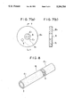
- FIG. 5(a) is a front elevational view of the first die D 1 ;
- FIG. 5(b) is a cross section taken along the line 5--5 in FIG. 5(a);
- FIG. 6(a) is a front elevational view of the second die D 2 ;
- FIG. 6(b) is a cross section taken along the line 6--6 in FIG. 6(a);
- FIG. 7(a) is a front elevational view of the third die D 3 ;
- FIG. 7(b) is a cross section taken along the line 7--7 in FIG. 7(a);
- FIG. 8 is a perspective view of the hollow molding E formed according to the present invention.
- FIG. 9 is a side view of the door seal S formed according to the present invention.
- FIG. 10 is a cross section taken along the line 10--10 in FIG. 9;
- FIG. 11 is a cross section taken along the line 11--11 in FIG. 9;
- FIG. 12 is a sectional view of the first door seal portion S 1 having no bridges 14 as shown by a dashed line;
- FIG. 13 is a side view of the door seal formed by the conventional molding method.
- a molding die D is constructed by overlapping first, second and third die parts D 1 , D 2 and D 3 .
- the first die part D 1 is formed substantially as a cylindrical-shaped plate or disk provided at its central portion with a first core C 1 having a semicircular cross section and projecting outwardly from a front surface of the die part D 1 .
- the first die part D 1 is further formed on its front surface with a molding material supply passage or groove V 1 extending from an outer circumference of the front surface to the first core C 1 .
- the supply passage V 1 intermediate the ends thereof, is formed with a recess 1 for receiving a base end of a molding material discharge pipe P which will be hereinafter described.
- the recess 1 is formed substantially as a blind cylindrical bore having an axial depth greater than that of the passage V 1 .
- the supply passage V 1 serves as a passage for supplying a molding material to be molded into a bridge 4 in a hollow portion 3 of a hollow molding E.
- the second die part D 2 is also formed substantially as a cylindrical-shaped plate or disk provided at its central portion with a second core C 2 having a semicircular cross section and projecting outwardly from a front surface of the die part D 2 .
- An extrusion opening 5 having a semicircular cross section is formed axially through the second die part D 2 at a position adjacent to the second core C 2 .
- the second die part D 2 is further formed on its front surface with a molding material supply passage or groove V 2 extending from an outer circumference of the front surface to the extrusion opening 5.
- the first core C 1 of the first die part D 1 is symmetrical with the second core C 2 of the second die part D 2 with respect to the axially aligned centers of the die parts D 1 and D 2 after they are overlapped.
- the supply passage V 2 serves as a passage for supplying a molding material to be molded into an upper half of a body portion 2 of the hollow molding E.
- the third die part D 3 is formed as a cylindrical-shaped plate or disk provided at its central portion with an extrusion opening 6 having a circular cross section and extending coaxially therethrough.
- the third die part D 3 is further formed on its rear surface with a molding material supply passage or groove V 3 extending from an outer circumference of the rear surface to the extrusion opening 6.
- the supply passage V 3 serves as a passage for supplying a molding material to be molded into a lower half of the body portion 2 of the hollow molding E.
- Both the second and third die parts D 2 and D 3 are formed with aligned pipe insert holes 7 extending axially therethrough for inserting the molding material discharge pipe P therethrough.
- the molding die D is assembled by inserting the first core C 1 of the first die part D 1 into the extrusion openings 5 and 6 of the second and third die parts D 2 and D 3 , inserting the second core C 2 of the second die part D 2 into the extrusion opening 6 of the third die part D 3 to thereby overlap the first, second and third die parts D 1 , D 2 and D 3 together, and thereafter inserting the molding material discharge pipe P into the pipe insert holes 7 of the second and third die parts D 2 and D 3 .
- the molding material discharge pipe P is closed at one end thereof, and is formed with a radially-directed opening 8 in the pipe sidewall near the closed end.
- an annular extrusion passage 9 for extruding the molding material to be molded into the body portion 2 of the hollow molding E is defined between the outer circumferential semicircular surfaces of the first and second cores C 1 and C 2 and the inner circumferential circular surface of the extrusion opening 6.
- another extrusion passage 11 for extruding the molding material to be molded into the bridge 4 of the hollow molding E is defined between the spaced but flat opposed surfaces of the first and second cores C 1 and C 2 .
- the molding material discharge pipe P is moved axially to open the supply passage V 1 as shown in FIG. 3, the molding material supplied to and through the supply passage V 1 is continuously extruded from the extrusion passage 11, thereby molding the bridge 4 of the hollow molding.
- a second hollow molding part E 2 having the bridge 4 in the hollow portion 3 is extrusion-molded.
- the molding lengths of the first and second hollow molded parts E 1 and E 2 can be defined by controlling a closed time and an open time of the supply passage V 1 by the operation of the molding material discharge pipe P.
- FIGS. 9 to 12 show a door seal S formed by utilizing the above principle.
- a first door seal portion S 1 having no bridge is employed in an area where a door mirror 12 is located
- a second door seal portion S 2 having a plurality of bridges 14 is employed in an area where a window glass 13 is located, so that the second door seal portion S 2 is required to tightly contact the window glass 13 by a large seal reaction.
- the first door seal portion S 1 is also employed at a corner area between a front side portion and an upper side portion of the door seal S, so that the seal portion S 1 may be readily deformed with a reduced seal reaction.
- the first and second door seal portions S 1 and S 2 can be alternately and continuously formed to obtain the door seal S. Therefore, in comparison with the conventional molding method, the connection at the corner portion between the front side portion and the upper side portion of the door seal S can be eliminated, and the bonding of the first seal portion S 1 and the second seal portion S 2 in the straight front side portion of the door seal S can also be eliminated. As a result, the number of manufacturing steps can be largely reduced to thereby remarkably improve the productivity.
- the first door seal portion having no bridge in the hollow portion and the second door seal portion having the bridge in the hollow portion can be continuously molded. Accordingly, the connection between the first and second door seal portions are eliminated to thereby improve the appearance. Moreover, the corner molding necessary in the conventional molding method can be eliminated to thereby largely reduce the number of manufacturing steps, resulting in remarkable improvement in the productivity.
Landscapes
- Engineering & Computer Science (AREA)
- Mechanical Engineering (AREA)
- Manufacturing & Machinery (AREA)
- Extrusion Moulding Of Plastics Or The Like (AREA)
- Seal Device For Vehicle (AREA)
- Specific Sealing Or Ventilating Devices For Doors And Windows (AREA)
- Rear-View Mirror Devices That Are Mounted On The Exterior Of The Vehicle (AREA)
- Vehicle Waterproofing, Decoration, And Sanitation Devices (AREA)
Abstract
Description
Claims (3)
Priority Applications (1)
| Application Number | Priority Date | Filing Date | Title |
|---|---|---|---|
| US08/338,897 US5486325A (en) | 1990-04-27 | 1994-11-14 | Seal molding method and device |
Applications Claiming Priority (2)
| Application Number | Priority Date | Filing Date | Title |
|---|---|---|---|
| JP2112258A JP2994425B2 (en) | 1990-04-27 | 1990-04-27 | Automotive hollow seal material and molding method thereof |
| JP2-112258 | 1990-04-27 |
Related Child Applications (1)
| Application Number | Title | Priority Date | Filing Date |
|---|---|---|---|
| US7334193A Division | 1990-04-27 | 1993-06-07 |
Publications (1)
| Publication Number | Publication Date |
|---|---|
| US5244704A true US5244704A (en) | 1993-09-14 |
Family
ID=14582203
Family Applications (2)
| Application Number | Title | Priority Date | Filing Date |
|---|---|---|---|
| US07/689,697 Expired - Fee Related US5244704A (en) | 1990-04-27 | 1991-04-19 | Door seal for automobile and molding method and device therefor |
| US08/338,897 Expired - Fee Related US5486325A (en) | 1990-04-27 | 1994-11-14 | Seal molding method and device |
Family Applications After (1)
| Application Number | Title | Priority Date | Filing Date |
|---|---|---|---|
| US08/338,897 Expired - Fee Related US5486325A (en) | 1990-04-27 | 1994-11-14 | Seal molding method and device |
Country Status (2)
| Country | Link |
|---|---|
| US (2) | US5244704A (en) |
| JP (1) | JP2994425B2 (en) |
Cited By (6)
| Publication number | Priority date | Publication date | Assignee | Title |
|---|---|---|---|---|
| WO1998029230A1 (en) * | 1997-01-03 | 1998-07-09 | Fm Plastics (S.A.R.L.) | Method and device for producing branched pipes or sheaths by extrusion, and pipes or sheaths resulting from the implementation |
| US5786087A (en) * | 1995-02-22 | 1998-07-28 | Specialty Filaments, Inc. | Honeycomb brush bristles and brush made therefrom |
| US6158171A (en) * | 1998-05-28 | 2000-12-12 | Overhead Door Corporation | Swing door seal and retainer assembly having a seal with interior webs |
| US6405489B1 (en) * | 1999-10-13 | 2002-06-18 | Toyoda Gosei Co., Ltd. | Structure for mounting door weather strip |
| US20060143988A1 (en) * | 2002-10-31 | 2006-07-06 | Martin Dillmann | Sealing billet for bodywork seals with a partially reinforced sealing profile section |
| CN103133856A (en) * | 2011-11-28 | 2013-06-05 | 上海龙胜实业有限公司 | Structure of thin-wall part with inner opening |
Families Citing this family (5)
| Publication number | Priority date | Publication date | Assignee | Title |
|---|---|---|---|---|
| JP3632304B2 (en) * | 1996-07-01 | 2005-03-23 | 豊田合成株式会社 | Weather strip, weather strip extrusion method and molding apparatus |
| DE19921458B4 (en) * | 1999-05-08 | 2009-12-24 | Technoform Caprano + Brunnhofer Ohg | Method and device for producing a hollow chamber profile made of thermoplastic material according to the cooling nozzle method |
| JP3970792B2 (en) * | 2003-03-28 | 2007-09-05 | 鬼怒川ゴム工業株式会社 | Extrusion molding method and extrusion molding apparatus |
| US7883332B2 (en) * | 2004-09-10 | 2011-02-08 | Metzeler Automotive Profile Systems Italy S.P.A. | Method and apparatus for producing a seal including a portion having a wall of variable thickness |
| CN110920026B (en) * | 2019-11-19 | 2021-09-14 | 西北橡胶塑料研究设计院有限公司 | Extrusion die for improving production efficiency of P-type rubber profile and production method thereof |
Citations (4)
| Publication number | Priority date | Publication date | Assignee | Title |
|---|---|---|---|---|
| US4455785A (en) * | 1981-10-21 | 1984-06-26 | Daimler-Benz Aktiengesellschaft | Seal for liftable and lowerable windows, especially side windows for passenger cars or station wagons |
| US4819382A (en) * | 1987-04-03 | 1989-04-11 | Toyoda Gosei Co., Ltd. | Weather strip for automobile |
| US4860495A (en) * | 1987-12-23 | 1989-08-29 | Gerald Kessler | Low friction plastic weatherstrip |
| US4976069A (en) * | 1988-11-02 | 1990-12-11 | Tokai Kogyo Kabushiki Kaisha | Automobile door seal, and a molding apparatus thereof |
Family Cites Families (10)
| Publication number | Priority date | Publication date | Assignee | Title |
|---|---|---|---|---|
| US4313327A (en) * | 1979-12-31 | 1982-02-02 | Peerless Of America, Inc. | Extrusion die for forming multi-passage tubular members |
| US4655987A (en) * | 1982-10-12 | 1987-04-07 | Guillermo Zertuche | Method and apparatus for extruding tubular articles having several conduits |
| IT1157134B (en) * | 1982-12-10 | 1987-02-11 | Saiag Spa | PROCEDURE AND EQUIPMENT FOR REALIZING A DRAWN CONTINUOUS EXTRUSION IN PARTICULAR A SEAL GASKET FOR BODYWORKS OF MOTOR VEHICLES PRESENTING SUBSEQUENT LENGTHS OF PRE-DETERMINED LENGTHS WITH EACH PRACTICAL PERFORMANCE AND PRACTICAL PERFORMANCE |
| SE435598B (en) * | 1983-04-12 | 1984-10-08 | Dziewanowski Andre | PROCEDURE AND DEVICE FOR MANUFACTURING EXTRUDED Pipes |
| JPS62214919A (en) * | 1986-03-18 | 1987-09-21 | Toyoda Gosei Co Ltd | Manufacture of extruded molded form |
| US4911873A (en) * | 1986-12-15 | 1990-03-27 | Toyoda Gosei Co., Ltd. | Terminal-treated extrusion and the method of terminal treatment therefor |
| JPH0661816B2 (en) * | 1988-03-24 | 1994-08-17 | 鬼怒川ゴム工業株式会社 | Profile extrusion die structure |
| US5110529A (en) * | 1990-02-28 | 1992-05-05 | Tokai Kogyo Kabushiki Kaisha | Process for producing hollow moldings |
| JP2864160B2 (en) * | 1990-08-29 | 1999-03-03 | 東海興業株式会社 | Method and apparatus for forming tubular member |
| JP3212624B2 (en) * | 1991-01-14 | 2001-09-25 | 東海興業株式会社 | Panel frame manufacturing method and manufacturing apparatus |
-
1990
- 1990-04-27 JP JP2112258A patent/JP2994425B2/en not_active Expired - Fee Related
-
1991
- 1991-04-19 US US07/689,697 patent/US5244704A/en not_active Expired - Fee Related
-
1994
- 1994-11-14 US US08/338,897 patent/US5486325A/en not_active Expired - Fee Related
Patent Citations (4)
| Publication number | Priority date | Publication date | Assignee | Title |
|---|---|---|---|---|
| US4455785A (en) * | 1981-10-21 | 1984-06-26 | Daimler-Benz Aktiengesellschaft | Seal for liftable and lowerable windows, especially side windows for passenger cars or station wagons |
| US4819382A (en) * | 1987-04-03 | 1989-04-11 | Toyoda Gosei Co., Ltd. | Weather strip for automobile |
| US4860495A (en) * | 1987-12-23 | 1989-08-29 | Gerald Kessler | Low friction plastic weatherstrip |
| US4976069A (en) * | 1988-11-02 | 1990-12-11 | Tokai Kogyo Kabushiki Kaisha | Automobile door seal, and a molding apparatus thereof |
Cited By (8)
| Publication number | Priority date | Publication date | Assignee | Title |
|---|---|---|---|---|
| US5786087A (en) * | 1995-02-22 | 1998-07-28 | Specialty Filaments, Inc. | Honeycomb brush bristles and brush made therefrom |
| WO1998029230A1 (en) * | 1997-01-03 | 1998-07-09 | Fm Plastics (S.A.R.L.) | Method and device for producing branched pipes or sheaths by extrusion, and pipes or sheaths resulting from the implementation |
| FR2758107A1 (en) * | 1997-01-03 | 1998-07-10 | Fm Plastics Sarl | PROCESS AND DEVICE FOR THE MANUFACTURE OF EXTRUDED BRANCHED PIPES, AND THE PIPES RESULTING FROM THEIR IMPLEMENTATION |
| US6158171A (en) * | 1998-05-28 | 2000-12-12 | Overhead Door Corporation | Swing door seal and retainer assembly having a seal with interior webs |
| US6405489B1 (en) * | 1999-10-13 | 2002-06-18 | Toyoda Gosei Co., Ltd. | Structure for mounting door weather strip |
| US20060143988A1 (en) * | 2002-10-31 | 2006-07-06 | Martin Dillmann | Sealing billet for bodywork seals with a partially reinforced sealing profile section |
| CN103133856A (en) * | 2011-11-28 | 2013-06-05 | 上海龙胜实业有限公司 | Structure of thin-wall part with inner opening |
| CN103133856B (en) * | 2011-11-28 | 2015-08-26 | 上海龙胜实业有限公司 | A kind of structure having the thin-walled parts of inside opening |
Also Published As
| Publication number | Publication date |
|---|---|
| US5486325A (en) | 1996-01-23 |
| JP2994425B2 (en) | 1999-12-27 |
| JPH0410922A (en) | 1992-01-16 |
Similar Documents
| Publication | Publication Date | Title |
|---|---|---|
| US5244704A (en) | Door seal for automobile and molding method and device therefor | |
| JPS59171735A (en) | Airtight material for automobile body and head for extrusionmolding said material | |
| KR100468194B1 (en) | Flange cover with smooth exterior surface | |
| CA2188249A1 (en) | Variable cross section extruding die and variable cross section extrusion molding method | |
| US5110529A (en) | Process for producing hollow moldings | |
| ES446727A1 (en) | Sealing joints for automobile body and an extrusion head for extruding such joints | |
| JPH0332823A (en) | Connecting method for weather strip | |
| US4874305A (en) | Accumulator extrusion head for producing striped parisons | |
| JP2005306344A (en) | Extrusion molded article having core material | |
| JPH106379A (en) | Production of weather strip for car | |
| EP0407364B1 (en) | A weatherstrip for motor-vehicle bodywork, an extrusion head and a method for producing the weatherstrip | |
| CA2109225A1 (en) | Accumulator Head for Extrusion Blow Molding Machine | |
| IT9009427A1 (en) | SEALING CLOSURE SYSTEM FOR WINDOWS OF MOTOR VEHICLES AND SIMILAR | |
| JP2543128B2 (en) | Profile extrusion die structure | |
| JPH1016029A (en) | Weather strip, extrusion-molding of weather strip and molding device | |
| ITTO20001048A1 (en) | METHOD AND DEVICE FOR THE CONSTRUCTION OF A TWO-COMPONENT LAYER OF A TIRE. | |
| JPH02111519A (en) | Molding device of hermetically sealing material for automobile | |
| JP2720078B2 (en) | Hollow weather strip and molding method thereof | |
| JPS634769B2 (en) | ||
| JP3046088B2 (en) | Sealing material for vehicle body opening and manufacturing method thereof | |
| JPH0726549Y2 (en) | Resin door frame | |
| JPH07315146A (en) | Weather strip for automobile | |
| JP3124434B2 (en) | Extruded product with irregular cross-section and method of manufacturing the same | |
| JPH05322048A (en) | Seal ring and its manufacture | |
| JPH0736843Y2 (en) | Bumper mall |
Legal Events
| Date | Code | Title | Description |
|---|---|---|---|
| AS | Assignment |
Owner name: TOKAI KOGYO CO., LTD., 1, NAGANE-CHO 4-CHOME, OHBU Free format text: ASSIGNMENT OF ASSIGNORS INTEREST.;ASSIGNOR:ARIMA, HIDETOSHI;REEL/FRAME:005685/0317 Effective date: 19910412 |
|
| FEPP | Fee payment procedure |
Free format text: PAYOR NUMBER ASSIGNED (ORIGINAL EVENT CODE: ASPN); ENTITY STATUS OF PATENT OWNER: LARGE ENTITY |
|
| CC | Certificate of correction | ||
| FPAY | Fee payment |
Year of fee payment: 4 |
|
| FPAY | Fee payment |
Year of fee payment: 8 |
|
| REMI | Maintenance fee reminder mailed | ||
| LAPS | Lapse for failure to pay maintenance fees | ||
| LAPS | Lapse for failure to pay maintenance fees |
Free format text: PATENT EXPIRED FOR FAILURE TO PAY MAINTENANCE FEES (ORIGINAL EVENT CODE: EXP.); ENTITY STATUS OF PATENT OWNER: LARGE ENTITY |
|
| STCH | Information on status: patent discontinuation |
Free format text: PATENT EXPIRED DUE TO NONPAYMENT OF MAINTENANCE FEES UNDER 37 CFR 1.362 |
|
| FP | Lapsed due to failure to pay maintenance fee |
Effective date: 20050914 |