US524392A - Furnace - Google Patents
Furnace Download PDFInfo
- Publication number
- US524392A US524392A US524392DA US524392A US 524392 A US524392 A US 524392A US 524392D A US524392D A US 524392DA US 524392 A US524392 A US 524392A
- Authority
- US
- United States
- Prior art keywords
- chamber
- retort
- boiler
- air
- combustion
- Prior art date
- Legal status (The legal status is an assumption and is not a legal conclusion. Google has not performed a legal analysis and makes no representation as to the accuracy of the status listed.)
- Expired - Lifetime
Links
- 238000002485 combustion reaction Methods 0.000 description 34
- 239000000446 fuel Substances 0.000 description 28
- 239000007789 gas Substances 0.000 description 16
- 239000000203 mixture Substances 0.000 description 10
- 239000002956 ash Substances 0.000 description 8
- 238000010438 heat treatment Methods 0.000 description 6
- ZOAMBXDOGPRZLP-UHFFFAOYSA-N Indole-3-acetamide Natural products C1=CC=C2C(CC(=O)N)=CNC2=C1 ZOAMBXDOGPRZLP-UHFFFAOYSA-N 0.000 description 4
- 239000011449 brick Substances 0.000 description 4
- UFHFLCQGNIYNRP-UHFFFAOYSA-N hydrogen Chemical compound [H][H] UFHFLCQGNIYNRP-UHFFFAOYSA-N 0.000 description 4
- 239000000463 material Substances 0.000 description 4
- 239000011819 refractory material Substances 0.000 description 4
- 230000001105 regulatory Effects 0.000 description 4
- 239000000779 smoke Substances 0.000 description 4
- 241001076939 Artines Species 0.000 description 2
- 235000002918 Fraxinus excelsior Nutrition 0.000 description 2
- OKTJSMMVPCPJKN-UHFFFAOYSA-N carbon Chemical compound [C] OKTJSMMVPCPJKN-UHFFFAOYSA-N 0.000 description 2
- 238000004140 cleaning Methods 0.000 description 2
- 238000010276 construction Methods 0.000 description 2
- 239000004071 soot Substances 0.000 description 2
Images
Classifications
-
- F—MECHANICAL ENGINEERING; LIGHTING; HEATING; WEAPONS; BLASTING
- F23—COMBUSTION APPARATUS; COMBUSTION PROCESSES
- F23B—METHODS OR APPARATUS FOR COMBUSTION USING ONLY SOLID FUEL
- F23B5/00—Combustion apparatus with arrangements for burning uncombusted material from primary combustion
Definitions
- Our invention relates particularly to boiler furnaces, and has for its object to provide a simple, economical and eflficient boiler fur nace, particularly adapted to the complete combustion of fuel and the attainment of a very high degree of economy in the consumption of the same; and it consists in the details of construction, combinations and arrangements hereinafter described and claimed.
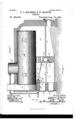
- Figure 1 is a side elevation of our improved boiler and furnace, partly in section;
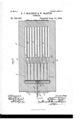
- Fig. 2 a horizontal section taken on the line 2 of Fig. 1, looking in the direction of the arrow;
- Fig. 3 a transverse section taken on the line 3 of Fig. 1;
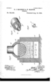
- Fig. 4. a perspective view of a portion of the retort located in the fire box;
- Fig. 5 an enlarged view of one of the draft regulators at the end of the feed air tubes.
- we us'ea' boiler A preferably of the return flue type and provided with the usual uptake 01., which leads to the smoke stack to carry 0% the products of combustion.
- the boiler may be supported in any of the usual ways, by the side walls a and by the front walls on, so as to leave an opening between the bottom of the, boiler and the ground.
- a bridge Wall B Located in this opening, preferably about midway in the length of the boiler and between the boiler and the ground, is a bridge Wall B, which may be formed 'of ordinary fire brick, and which rises to a height of about ten 'inches above the grate bars b.
- boiler proper with a structure composed first of a layer of fire bricks, through which extends a series of square openings 1) and above this several layers of tiling formed of refractory material and provided preferably with longitudinal circular openings b so that the portion of the bridge wall between the boiler from about ten inches above the fire grate is provided with a series of longitudinal open ings arranged in any convenient manner, so as to furnish a communication between the fuel chamber 0 and the combustion chamber PATENT OFFICE.
- the bridge wall is provided with an air chamber.
- E which communicates with the outer air by means of a series of feed air tubes e, which, in turn, are provided with dampers, e, at their outer ends for the purpose of regulating the amoiLnt T
- air chamber communicates with the longitudinal openings in the bridge wall by means of a series of channels 6 and the entire bridge wall is ramified with a number of these channels which connect the longitudinal openings with each other and with theair chamber, for the purpose of furnishing and distributing a sufficient amount of atmospheric air to promote the combustion of the heated gases as they pass through the bridge wall on their way to the combustion chamber.
- Thebridge wall is also provided with a numberof openings a which connect the air chamber with the ash pit for the purposeof furnishing a means by which the,air chamber may be cleaned when it becomes clogged by the deposit of soot or other unconsumed material.
- the front wall a which acts as a support for one endof the boiler, is provided with the usual doors a which communicate with the fire box and serve as a fuel door, or as an inlet for the admission of air to support combustion; and the door a which communicates with the ash pit, F, to permit the removal of ashes, also serves as an inlet for theadmission of air which enters into combustion with the heated gases in the furnace box.
- a retort G Located preferably in the upperfrontcor ner of the fire box is a retort G, preferablymade of hydraulic tubing, and provided with 100' a series of nozzles 9, extending out in a direction toward the lower set of longitudinal openings in the bridge wall.
- This retort is surrounded by a jacket of refractory material 9', made in several sections, which entirely incloses the retort and its nozzles, serving thereby to protect the metallic retort from the disintegrating influences of the heat, as well as-to act as a reservoir for the storage of a certain amount of heat.
- jacket may be provided with several longitudinal openings 9 through which may be inserted tie bolts for the purpose of bolting the jacket together and thereby preventing it falling to pieces, which it otherwise might do when cracked or broken by the action of the heat.
- the retort is supported in position by having its ends inserted a short distance into the side walls of the furnace, and the.
- the chamber in the retort communicates with and is connected to the steam dome A of the boiler, by means of a pipe g which may be provided with an ordinary valve at its lower end for the purpose of regulating the amount of steam furnished from the boiler to the retort,
- the hydrogen gas and theheated gases passing through this perforated bridge wall are furnished the requisite amount of air from the air chamber in the bridge Wall to support combustion, and, passing out into the combustion chamber, a more perfect combustion takes place, and the flame, developing in the same, passes to the rear end of the boiler, back through the tubes in the same to the front of the boiler; and by this time the gases being nearly consumed, the products of combustion pass out through the up-take into the smoke stack.
- a heating apparatus the combination of a furnace provided with a fuel chamber, a combustion chamber, a perforated bridgewall separating said chambers and provided with an air chamber, means for furnishing the supply of air to such chamber, a retort located within the fuel chamber for holding a supply of superheated steam, and provided with a series of nozzles arranged and extending out in the direction to expel the superheated steam toward and against the lower set of openings in the bridge-wall, substantially as described.
- a heating apparatus the combination of a furnace provided with a fuel chamber, a retort located within the fuel chamber provided with a series of nozzles, a refractory jacket surrounding the retort and nozzles and made of several sections, and a pipe connecting the chamber of the retort with a source of steam supply, so constructed and arranged that the refractory jacket may be removed and a new one inserted without disturbihg the retort proper, substantially as described.
- a heating apparatus the combination of a furnace provided with fuel and combustion chambers, a bridge wall separating such chambers, provided with an air chamber and longitudinal and vertical perforations connected with each other and with such air chamber, and a setof feed air tubes extending through the combustion chamber and connecting the air chamber with a supply of atmospheric air, substantially as described.
- a furnace provided with a fuel chamber, a combustion chamber, a perforated bridge wall separating said chambers and provided with an air chamber and channels connecting the longitudinal perforations with each other and the air chamber, means for furnishing air to the air chamber in the bridge wall, a retort provided with a series of nozzles located in the fuel chamber adapted to hold steam at boiler pressure, and a tube coning the longitudinal perforations with each chamber with a's'ource of steam supply, subother and the air chamber, means for furstantially as described.
- fractory material surrounding the retort and THOMAS E SHERIDAN, nozzles, and a tube connecting the retort SAMUEL E. HIBBEN.
Description
v '3 Sheets-Sheet 1.
D. J. McKENZIB &-. W. MARTIN.
FURNAGE. v
Patented Aug. 14, 194.
(No Model.)
( No Model.) a Sheets-Sheet 2. D. J. MCKENZIE 8v W. MARTIN.
' FURNACE.
No.-524,392. Paj'gnted Aug. 14, 13.94.
UNIT D STATES DOUGAL J. MCKENZIE AND WILLIAM MARTIN, OF CHICAGO, ILLI oIs.
FURNACE.
SPECIFICATION forming part of Letters Patent No. 524,392, dated August 14, 1894. Application filed July 21, 1893. fierial No. 481,151. (No modeL To all whom it may concern.-
'Be it known that we, DOUGAL J MCKENZIE and WIL IAM'MARTIN, of Chicago, Illinois, have Invented certain new and useful Improvements in Furnaces, of which the followmg 1s a specification.
Our invention relates particularly to boiler furnaces, and has for its object to provide a simple, economical and eflficient boiler fur nace, particularly adapted to the complete combustion of fuel and the attainment of a very high degree of economy in the consumption of the same; and it consists in the details of construction, combinations and arrangements hereinafter described and claimed.
In the drawings, Figure 1 is a side elevation of our improved boiler and furnace, partly in section; Fig. 2 a horizontal section taken on the line 2 of Fig. 1, looking in the direction of the arrow; Fig. 3 a transverse section taken on the line 3 of Fig. 1; Fig. 4. a perspective view of a portion of the retort located in the fire box; and Fig. 5 an enlarged view of one of the draft regulators at the end of the feed air tubes.
In illustratingour improved furnace, we
have shown it in connection with one class of boilers, via, an external fired tubular boiler; but do not desire to be limited to this particular class of boilers, as the invention is capable, with slight mechanical changes, of being adapted and used in, connection with any of the different classes of boilers now In use.
In constructing our improved boiler fur-' nace, we us'ea' boiler A, preferably of the return flue type and provided with the usual uptake 01., which leads to the smoke stack to carry 0% the products of combustion. The boiler may be supported in any of the usual ways, by the side walls a and by the front walls on, so as to leave an opening between the bottom of the, boiler and the ground. Located in this opening, preferably about midway in the length of the boiler and between the boiler and the ground, is a bridge Wall B, which may be formed 'of ordinary fire brick, and which rises to a height of about ten 'inches above the grate bars b. We fill the space between this bridge wall and the of air admitted into the air chamber.
boiler proper with a structure composed first of a layer of fire bricks, through which extends a series of square openings 1) and above this several layers of tiling formed of refractory material and provided preferably with longitudinal circular openings b so that the portion of the bridge wall between the boiler from about ten inches above the fire grate is provided with a series of longitudinal open ings arranged in any convenient manner, so as to furnish a communication between the fuel chamber 0 and the combustion chamber PATENT OFFICE.
D, through which-the heated gases must pass 7 on their way to the up-take. The bridge wall is provided with an air chamber. E, which communicates with the outer air by means of a series of feed air tubes e, which, in turn, are provided with dampers, e, at their outer ends for the purpose of regulating the amoiLnt T is air chamber communicates with the longitudinal openings in the bridge wall by means of a series of channels 6 and the entire bridge wall is ramified with a number of these channels which connect the longitudinal openings with each other and with theair chamber, for the purpose of furnishing and distributing a sufficient amount of atmospheric air to promote the combustion of the heated gases as they pass through the bridge wall on their way to the combustion chamber. Thebridge wall is also provided with a numberof openings a which connect the air chamber with the ash pit for the purposeof furnishing a means by which the,air chamber may be cleaned when it becomes clogged by the deposit of soot or other unconsumed material.
The front wall a which acts as a support for one endof the boiler, is provided with the usual doors a which communicate with the fire box and serve as a fuel door, or as an inlet for the admission of air to support combustion; and the door a which communicates with the ash pit, F, to permit the removal of ashes, also serves as an inlet for theadmission of air which enters into combustion with the heated gases in the furnace box.
Located preferably in the upperfrontcor ner of the fire box is a retort G, preferablymade of hydraulic tubing, and provided with 100' a series of nozzles 9, extending out in a direction toward the lower set of longitudinal openings in the bridge wall. This retort is surrounded by a jacket of refractory material 9', made in several sections, which entirely incloses the retort and its nozzles, serving thereby to protect the metallic retort from the disintegrating influences of the heat, as well as-to act as a reservoir for the storage of a certain amount of heat. By making the retort jacket in sections-first in half, and then each individual half in sections,-it allows the jacket to be easily taken off when consumed and a new one replaced. The
jacket may be provided with several longitudinal openings 9 through which may be inserted tie bolts for the purpose of bolting the jacket together and thereby preventing it falling to pieces, which it otherwise might do when cracked or broken by the action of the heat. The retort is supported in position by having its ends inserted a short distance into the side walls of the furnace, and the.
central portion supported by means of acorbeled projecting bridge 9 The chamber in the retort communicates with and is connected to the steam dome A of the boiler, by means of a pipe g which may be provided with an ordinary valve at its lower end for the purpose of regulating the amount of steam furnished from the boiler to the retort,
thereby allowing the retort to be filled with.
steam at boiler pressure.
In using our improved furnace, fuel is supplied in the usual manner to the grate bars, and, after ignition, the requisite amount of air is furnished through the ash pit by means of the usual openings in the door of the same.
-When the fuel has attained a very high degree of heat, steam is admitted preferably from the boiler to the retort in the fuel chamber, where it becomes superheated, and is projected through the nozzles of the retort .across the mass of incandescent fuel in a gaseous state-the steam having been decomposed and hydrogen gas liberated. The immense force thereby given forth from this retort throws the highly heated gases against the bridge wall and serves to heat the bridge wall to a state of incandescence. The hydrogen gas and theheated gases passing through this perforated bridge wall are furnished the requisite amount of air from the air chamber in the bridge Wall to support combustion, and, passing out into the combustion chamber, a more perfect combustion takes place, and the flame, developing in the same, passes to the rear end of the boiler, back through the tubes in the same to the front of the boiler; and by this time the gases being nearly consumed, the products of combustion pass out through the up-take into the smoke stack.
As the flames expand in the combustion chamber, they contact the series of metallic chamber and is mixed with'the heated gases,
and thus serves to assist the combustion, and not check or lessen the degree of heat of the flame or gases as they are mingled with the air.
We claim- 1. In a heating apparatus, the combination of a furnace provided with a fuel chamber, a combustion chamber, a perforated bridgewall separating said chambers and provided with an air chamber, means for furnishing the supply of air to such chamber, a retort located within the fuel chamber for holding a supply of superheated steam, and provided with a series of nozzles arranged and extending out in the direction to expel the superheated steam toward and against the lower set of openings in the bridge-wall, substantially as described.
2. In a heating apparatus, the combination of a furnace provided with a fuel chamber, a retort located within the fuel chamber provided with a series of nozzles, a refractory jacket surrounding the retort and nozzles and made of several sections, and a pipe connecting the chamber of the retort with a source of steam supply, so constructed and arranged that the refractory jacket may be removed and a new one inserted without disturbihg the retort proper, substantially as described.
3. In a heating apparatus, the combination of a furnace provided with fuel and combustion chambers, a bridge wall separating such chambers, provided with an air chamber and longitudinal and vertical perforations connected with each other and with such air chamber, and a setof feed air tubes extending through the combustion chamber and connecting the air chamber with a supply of atmospheric air, substantially as described.
4.. In aheating apparatus, the combination of a furnace provided with a fuel chamber, a combustion chamber, a perforated bridge wall separating said chambers and provided with an air chamber and channels connecting the longitudinal perforations with each other and the air chamber, means for furnishing air to the air chamber in the bridge wall, a retort provided with a series of nozzles located in the fuel chamber adapted to hold steam at boiler pressure, and a tube coning the longitudinal perforations with each chamber with a's'ource of steam supply, subother and the air chamber, means for furstantially as described. i nishing air to the air chamber in the bridge, DOUGAL J MCKENZIE wall, a retort provided with a series of noz- NVILLIAM ARTIN 5 zles located in the fuelchamber adapted to L hold steam at boiler pressure, a jacket of re- Witnesses:
fractory material surrounding the retort and THOMAS E: SHERIDAN, nozzles, and a tube connecting the retort SAMUEL E. HIBBEN.
Publications (1)
| Publication Number | Publication Date |
|---|---|
| US524392A true US524392A (en) | 1894-08-14 |
Family
ID=2593186
Family Applications (1)
| Application Number | Title | Priority Date | Filing Date |
|---|---|---|---|
| US524392D Expired - Lifetime US524392A (en) | Furnace |
Country Status (1)
| Country | Link |
|---|---|
| US (1) | US524392A (en) |
-
0
- US US524392D patent/US524392A/en not_active Expired - Lifetime
Similar Documents
| Publication | Publication Date | Title |
|---|---|---|
| US524392A (en) | Furnace | |
| US608161A (en) | Longo | |
| US61031A (en) | Hhhhhi | |
| US577637A (en) | Furnace for smokeless combustion | |
| US356988A (en) | Steam-generator | |
| US514869A (en) | Smokeless boiler | |
| US996868A (en) | Furnace. | |
| US521863A (en) | Steam-boiler furnace | |
| US212366A (en) | Improvement in furnaces | |
| US143004A (en) | Improvement in smoke-burning furnaces | |
| US182057A (en) | Improvement in furnaces for steam-boilers | |
| US652110A (en) | Furnace. | |
| US211118A (en) | Improvement in steam-generators | |
| US523089A (en) | trapp | |
| US425072A (en) | James s | |
| US288418A (en) | Furnace for steam boilees | |
| US517497A (en) | Bagasse-furnace | |
| US426694A (en) | Steam-boiler furnace | |
| US748374A (en) | Boiler-furnace. | |
| US330136A (en) | mailer | |
| US624476A (en) | l gordon | |
| US748748A (en) | kiigsley | |
| US286286A (en) | Fuenaoe | |
| US834058A (en) | Boiler-furnace. | |
| US402362A (en) | Smoke-consuming boiler-furnace |