US5240353A - Anchor with deoperable screw - Google Patents
Anchor with deoperable screw Download PDFInfo
- Publication number
- US5240353A US5240353A US07/981,880 US98188092A US5240353A US 5240353 A US5240353 A US 5240353A US 98188092 A US98188092 A US 98188092A US 5240353 A US5240353 A US 5240353A
- Authority
- US
- United States
- Prior art keywords
- shaft
- anchor
- axis
- end portion
- dog
- Prior art date
- Legal status (The legal status is an assumption and is not a legal conclusion. Google has not performed a legal analysis and makes no representation as to the accuracy of the status listed.)
- Expired - Fee Related
Links
- 239000002689 soil Substances 0.000 claims abstract description 48
- 239000000126 substance Substances 0.000 claims abstract description 21
- 230000014759 maintenance of location Effects 0.000 claims description 8
- 241000282472 Canis lupus familiaris Species 0.000 description 69
- 239000000463 material Substances 0.000 description 9
- 239000004576 sand Substances 0.000 description 8
- 230000013011 mating Effects 0.000 description 7
- 238000000926 separation method Methods 0.000 description 7
- 229910001220 stainless steel Inorganic materials 0.000 description 5
- 239000010935 stainless steel Substances 0.000 description 5
- 238000003466 welding Methods 0.000 description 5
- 238000009434 installation Methods 0.000 description 3
- 125000006850 spacer group Chemical group 0.000 description 3
- 229910000906 Bronze Inorganic materials 0.000 description 2
- BQCADISMDOOEFD-UHFFFAOYSA-N Silver Chemical compound [Ag] BQCADISMDOOEFD-UHFFFAOYSA-N 0.000 description 2
- 239000010974 bronze Substances 0.000 description 2
- 238000010276 construction Methods 0.000 description 2
- KUNSUQLRTQLHQQ-UHFFFAOYSA-N copper tin Chemical compound [Cu].[Sn] KUNSUQLRTQLHQQ-UHFFFAOYSA-N 0.000 description 2
- 239000002184 metal Substances 0.000 description 2
- 229910052751 metal Inorganic materials 0.000 description 2
- 238000012986 modification Methods 0.000 description 2
- 230000004048 modification Effects 0.000 description 2
- 230000000717 retained effect Effects 0.000 description 2
- 229910052709 silver Inorganic materials 0.000 description 2
- 239000004332 silver Substances 0.000 description 2
- 238000005476 soldering Methods 0.000 description 2
- 229910000831 Steel Inorganic materials 0.000 description 1
- 238000005452 bending Methods 0.000 description 1
- 210000000078 claw Anatomy 0.000 description 1
- 230000000295 complement effect Effects 0.000 description 1
- 230000008878 coupling Effects 0.000 description 1
- 238000010168 coupling process Methods 0.000 description 1
- 238000005859 coupling reaction Methods 0.000 description 1
- 238000002474 experimental method Methods 0.000 description 1
- 230000000284 resting effect Effects 0.000 description 1
- 239000010959 steel Substances 0.000 description 1
- 239000002023 wood Substances 0.000 description 1
Images


Classifications
-
- B—PERFORMING OPERATIONS; TRANSPORTING
- B63—SHIPS OR OTHER WATERBORNE VESSELS; RELATED EQUIPMENT
- B63B—SHIPS OR OTHER WATERBORNE VESSELS; EQUIPMENT FOR SHIPPING
- B63B21/00—Tying-up; Shifting, towing, or pushing equipment; Anchoring
- B63B21/24—Anchors
- B63B21/26—Anchors securing to bed
-
- E—FIXED CONSTRUCTIONS
- E02—HYDRAULIC ENGINEERING; FOUNDATIONS; SOIL SHIFTING
- E02D—FOUNDATIONS; EXCAVATIONS; EMBANKMENTS; UNDERGROUND OR UNDERWATER STRUCTURES
- E02D5/00—Bulkheads, piles, or other structural elements specially adapted to foundation engineering
- E02D5/74—Means for anchoring structural elements or bulkheads
- E02D5/80—Ground anchors
- E02D5/801—Ground anchors driven by screwing
-
- E—FIXED CONSTRUCTIONS
- E21—EARTH DRILLING; MINING
- E21B—EARTH DRILLING, e.g. DEEP DRILLING; OBTAINING OIL, GAS, WATER, SOLUBLE OR MELTABLE MATERIALS OR A SLURRY OF MINERALS FROM WELLS
- E21B10/00—Drill bits
- E21B10/44—Bits with helical conveying portion, e.g. screw type bits; Augers with leading portion or with detachable parts
-
- E—FIXED CONSTRUCTIONS
- E21—EARTH DRILLING; MINING
- E21B—EARTH DRILLING, e.g. DEEP DRILLING; OBTAINING OIL, GAS, WATER, SOLUBLE OR MELTABLE MATERIALS OR A SLURRY OF MINERALS FROM WELLS
- E21B17/00—Drilling rods or pipes; Flexible drill strings; Kellies; Drill collars; Sucker rods; Cables; Casings; Tubings
- E21B17/02—Couplings; joints
- E21B17/023—Arrangements for connecting cables or wirelines to downhole devices
-
- E—FIXED CONSTRUCTIONS
- E21—EARTH DRILLING; MINING
- E21B—EARTH DRILLING, e.g. DEEP DRILLING; OBTAINING OIL, GAS, WATER, SOLUBLE OR MELTABLE MATERIALS OR A SLURRY OF MINERALS FROM WELLS
- E21B17/00—Drilling rods or pipes; Flexible drill strings; Kellies; Drill collars; Sucker rods; Cables; Casings; Tubings
- E21B17/02—Couplings; joints
- E21B17/04—Couplings; joints between rod or the like and bit or between rod and rod or the like
- E21B17/06—Releasing-joints, e.g. safety joints
Abstract
An anchor for boring into a deformable substance which includes an elongate shaft adapted for disposition in the deformable substance is provided. The anchor has proximal and distal end portions and a central longitudinal axis. A handle is carried by the proximal end portion for causing rotation of the shaft about the axis. A drive screw is carried by the distal end portion for moving the shaft in opposite first and second longitudinal directions when the shaft is rotated in respective opposite first and second rotational directions about the axis. The anchor also includes a disengagement assembly carried by the shaft for deactivating the drive screw so that the shaft can rotate relatively freely without longitudinal movement thereof. The drive screw has an outer surface with a helical screw thread formed thereon and is rotatably mounted to the shaft distal end portion for rotation about the axis. The disengagement assembly includes a clutch assembly carried within the shaft for rotationally locking and delocking the drive screw with the shaft. In one embodiment, the end piece has a tip for piercing the soil. In another embodiment, the shaft and screw are provided with longitudinal bores therethrough for permitting the passage of soil therethrough. A fin with a leading end can be pivotly mounted near the trailing edge of the drive screw thread for increasing the torque necessary to rotate the end piece in the second rotational direction.
Description
This invention pertains generally to anchors, and more particularly to anchors with screws at the end thereof.
Anchors have been provided for disposition in sand, soil and deformable substances for securing objects ranging in size from scuba equipment and skis to boats and construction equipment thereto. In general, these anchors can be divided into two categories: anchors of a permanent nature and anchors of a more temporary nature. Most permanent anchors cannot be readily removed or reused. On the other hand, most temporary anchors can be too easily removed and therefore do not provide meaningful protection against theft of the objects secured thereto.
It is in general an object of the invention to provide a new and improved anchor with a screw on the distal end which overcomes the limitations and disadvantages of the anchors currently provided.
Another object of the invention is to provide an anchor of the above character which can be easily placed in deformable substances such as sand or soil without the use of any tools.
Another object of the invention is to provide an anchor of the above character which can be locked to preclude its unauthorized removal from the sand or soil.
Another object of the invention is to provide an anchor of the above character to which objects can be secured.
Another object of the invention is to provide an anchor of the above character which, when unlocked, can be readily removed from the sand or soil for reuse.
Another object of the invention is to provide an anchor of the above character which can be folded for ease of storage and transportation.
These and other objects are achieved in accordance with the invention by providing an anchor for boring into deformable substances which includes an elongate shaft adapted for disposition in the deformable substance and having proximal and distal end portions and a central longitudinal axis. Means is carried by the proximal end portion for causing rotation of the shaft about the axis, and drive screw means is carried by the distal end portion for moving the shaft in a first longitudinal direction when the shaft is rotated in a first rotational direction about the axis and for moving the shaft in an opposite second longitudinal direction when the shaft is rotated in an opposite second rotational direction about the axis. The anchor also includes disengagement means carried by the shaft for deactivating the drive screw means so that the shaft can rotate relatively freely without longitudinal movement thereof.
The drive screw means includes an end piece having an outer surface with a helical screw thread formed thereon and mounting means for rotatably mounting the end piece to the distal end portion of the shaft to permit rotation about said axis. The disengagement means includes clutch means carried within the shaft for rotationally locking and delocking the end piece with the shaft. In one embodiment, the end piece has a tip for piercing the soil. In another embodiment, the shaft and end piece are formed with bore-forming inner surfaces which extend longitudinally therethrough for permitting soil to pass through the shaft and end piece as the anchor moves through the soil.
A fin with a leading end can be pivotly mounted near the trailing edge of the screw thread formed on the end piece for increasing the torque necessary to rotate the end piece in the second rotational direction. Pivot means is provided for pivoting the fin at its leading end when the shaft is rotated in the second rotational direction from a first position where the fin is in general juxtaposition with the screw thread to a second position where the fin is inclined with respect to the screw thread.
Attention is now directed to FIGS. 1 through 21, which are not necessarily drawn to scale.
FIG. 1 is a side elevational view of the anchor with deoperable screw of the present invention embedded in soil.
FIG. 2 is an enlarged side elevational view, partially cut away, of a portion of the anchor shown in FIG. 1 taken along the line 2--2 of FIG. 1 with the screw in an engaged condition.
FIG. 3 is an enlarged side elevation view similar to FIG. 2 of the anchor shown in FIG. 1 with the screw in a disengaged condition.
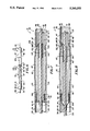
FIG. 4 is a cross-sectional view of a portion of the anchor shown in FIG. 1, rotated 90 degrees, with the screw in an engaged condition.
FIG. 5 is a cross-sectional view similar to FIG. 4 of the anchor shown in FIG. 1 with the screw in a disengaged condition.
FIG. 6 is an enlarged side elevational view of a portion of the anchor shown in FIG. 1, taken along the line 6--6 of FIG. 1 and rotated 90 degrees, with the first and second shaft sections unlocked and separated.
FIG. 7 is a cross-sectional view of a portion of the anchor shown in FIG. 1 rotated 90 degrees.
FIG. 8 is a cross-sectional view similar to FIG. 7 of the anchor shown in FIG. 1 with the first and second shaft sections unlocked and partially separated.
FIG. 9 is a cross-sectional view of a portion of the anchor shown in FIG. 1 when the screw is in an engaged condition.
FIG. 10 is a fragmentary cross-sectional view, similar to FIG. 9 but axially rotated 90 degrees, of the anchor shown in FIG. 1 when the screw is in a secured disengaged condition.
FIG. 11 is a fragmentary cross-sectional view similar to FIG. 9 when the first and second shaft sections are unlocked.
FIG. 12 is a fragmentary cross-sectional view similar to FIG. 9 when the first and second shaft sections are unlocked and separated.
FIG. 13 is a fragmentary cross-sectional view of the anchor shown in FIG. 9 taken along the line 13--13 of FIG. 9.
FIG. 14 is an enlarged side elevational view of a portion of the anchor screw shown in FIG. 1, rotated 90 degrees.
FIG. 15 is a side elevational view of the first and second shaft sections of the anchor shown in FIG. 1 in an unlocked and separated condition.
FIG. 16 is a side elevational view, partially cut away, of another embodiment of the anchor with deoperable screw of the present invention embedded in soil.
FIG. 17 is a cross-sectional view of the anchor shown in FIG. 16 taken along the line 17--17 of FIG. 16 with the screw in an engaged condition.
FIG. 18 is a fragmentary cross-sectional view similar to FIG. 17 of the anchor shown in FIG. 16 with the screw in a disengaged condition.
FIG. 19 is a cross-sectional view of the anchor shown in FIG. 17 taken along the line 19--19 of FIG. 17.
FIG. 20 is a cross-sectional view of the anchor shown in FIG. 17 taken along the line 20--20 of FIG. 17.
FIG. 21 is a cross-sectional view of the anchor shown in FIG. 18 taken along the line 21--21 of FIG. 18.
The locking portable anchor 31 of the present invention includes an elongate tubular shaft 32 which is adapted for disposition in a deformable substance such as soil. Shaft 32 is centered on a longitudinal axis 33 and is formed from first or bottom and second or top sections 36 and 37 as illustrated in FIG. 1. Bottom section 38 has an inner bore-forming surface 38 and an outer surface 41 which are each generally circular in cross-section, and a bottom end portion 42 which serves as the distal or bottom end portion of shaft 32 and an opposite top end portion 43. Similarly, top section 37 has an inner bore-forming surface 46 and an outer surface 47 which are each generally circular in cross-section, and a bottom end portion 48 and an opposite top end portion 51 which serves as the proximal or top end portion of shaft 32. Connector 56 serves as means for rigidly joining shaft sections 36 and 37 and is generally cylindrical in shape. Connector 56 has a central portion 57 which is hexagonal in cross-section and opposite first or bottom and second or top end portions 58 and 60 of reduced diameter (See FIGS. 6 through 8). A bore-forming inner surface 61, which has a circular-shaped cross-section, extends longitudinally through end portions 58 and 60 and is generally centered on axis 33. Connector end portions 58 and 60 extend into respective top and bottom end portions 43 and 48 of shaft sections 36 and 37, with shaft end portions 43 and 48 having similar ends 62 which are hexagonal in cross-sectional shape and dimensioned for snugly and nonrotatably receiving connector central portion 57. One or more dimples 63 formed in shaft top end portion 43 serve to attach connector 56 to shaft bottom section 36.
Mounting means or assembly 85 is provided for rotatably mounting screw 71 to bottom end portion 42 of shaft bottom section 36 to permit rotation of the screw about axis 33 and includes a generally cylindrical first dog element 86. First dog 86 has an annular shoulder 87 thereabout from which longitudinally extends a mounting portion 88 of a reduced diameter. Extending longitudinally and in the opposite direction from mounting portion 88 along one side of first dog 86 is a locking portion 89 which is generally semicircular in cross-sectional shape and formed from a recess 90 in the first dog. Locking portion 89 has a generally planar mating surface 91 parallel with axis 33.
A second dog element 105 is slidably carried within bottom end portion 42 of shaft 32 and, together with first dog 86, serves as part of the clutch means or assembly 106 carried by shaft bottom section 36 for rotationally locking and delocking screw 71 with shaft 32. Second dog 105 moves longitudinally with respect to axis 33 between a first engaged position with first dog 86 and a second disengaged position with the first dog. The second dog is generally cylindrical in shape and has a top tubular portion 107 with a longitudinal bore 108 extending therethrough and a bottom locking portion 111 extending longitudinally from the tubular portion along one side of second dog 105. Locking portion 111 is generally semicircular in cross-sectional shape, being formed from a recess 112, and has a generally planar mating surface 113 parallel with axis 33.
A tubular bulkhead 121 is included in shaft bottom section 36 for limiting the upward longitudinal travel of second dog 105 therein. Bulkhead 121 is configured and sized to snugly abut bottom section inner surface 38 and is rigidly mounted in bottom end portion 42 at a longitudinal position inwardly stop 116 and toward top end portion 43 by any suitable means not shown in the drawings such as welding. Bulkhead 121 has an annular shoulder 122 thereabout from which a stem portion 123 of reduced diameter extends toward stop 116, and is provided with a bore 126 extending longitudinally therethrough which is generally centered on axis 33. Second dog 105 is in a second or upper disengaged position when tubular portion 107 abuts bulkhead stem portion 123 as illustrated in FIG. 5.
Stop 116 also serves as means for rotatably locking and coupling second dog 105 to shaft bottom section 36. Second dog locking portion 111 is longitudinally sized and bulkhead 121 longitudinally disposed within bottom end portion 42 so that second dog mating surface 113 generally abuts stop mating surface 117 at all times. In this manner, as illustrated in FIGS. 4 and 5, second dog 105 rotates about axis 33 with shaft bottom section 36. When dogs 86 and 105 are in the first engaged position, as illustrated in FIG. 4, first dog 86 and screw 71 mounted thereto are rotatably coupled to second dog 105. In this position, first and second dog mating surfaces 91 and 113 abut to transmit torque from second dog 105 to first dog 86. When dogs 86 and 105 are in the second disengaged position, as illustrated in FIG. 5, the dogs are rotatably decoupled.
A spring means in the form of coil spring 131 is carried within shaft bottom section 36 for biasing second dog 105 toward the first engaged or home position. Spring 131 is sandwiched between fixed bulkhead shoulder 122 and second dog tubular portion 107, exerting a constant force on the tubular portion which urges second dog 105 downwardly within bottom section 36. When spring 131 is in its compressed condition, as illustrated in FIG. 5, bulkhead stem portion 123 assists in preventing the spring from assuming a damaging distorted configuration.
For assembling shaft bottom section 36, cable bottom end 137 is first fed through bulkhead 121, coil spring 131 and second dog 105 and secured within second dog bore 108 by retention tube 141 in the manner discussed above. This assembly is loaded through bottom end portion 42, and bulkhead 121 longitudinally positioned within and attached to bottom section 36. Stop 116 is then inserted in bottom end portion 42 and mounted to bottom section 36. After bushing 97 is slidably disposed about first dog mounting portion 88 and the mounting portion attached within screw bore 76 by expansion pin 92, first dog 86 and bushing 97 are slid into bottom end portion 42. Annular crimps 102 are formed on bottom section 36 for securing bushing 97, and hence first dog 86 and screw 71, to shaft 32.
Locking assembly 146 further includes a ball 148 disposed in a bore 151 extending through one side of connector top end portion 73. Either cable 36 or sleeve 146 contact ball at all times within connector 56 to prevent the ball from dislodging within connector 56. A lip 152 formed on top end portion 73 defines the outer radial extremity of bore 151 and is sized to retain ball 148 within bore 151. When locking assembly 145 is in its locked position and dogs 86 and 105 are in the second disengaged position, as illustrated in FIG. 7, sleeve 146 on cable 136 abuts ball 148 and presses it against lip 152. An annular crimp 153 formed in shaft bottom end portion 48 is longitudinally positioned thereon so that when bottom and top sections 36 and 37 are tightly secured together and sleeve outer surface 147 is engaging ball 151, the ball abuts crimp 153 preventing connector 56 from sliding out of bottom end portion 48. In this manner, connector 56 and shaft bottom section 36 are longitudinally locked with shaft top section 37. Sleeve 146 has a length sufficient to continually engage ball 148 when cable 136 is pulled upwardly to move second dog 105 to its second disengaged position. When cable 136 and sleeve 146 are moved downwardly within connector 56, as illustrated in FIG. 8, the sleeve moves out from under ball 148 so that the ball can move radially inwardly a sufficient distance to permit passage of crimp 153 and separation of bottom and top sections 36 and 37.
An elastic generally tubular boot 156 is attached to connector bottom end portion 58 for preventing soil or decontaminants which may enter connector top end portion 60 and shaft top end portion 43 from traveling down shaft bottom section 36 and possibly disrupting clutch assembly 106 and/or mounting assembly 85. Boot 156 has a bottom opening 157 for snugly receiving cable 136 and an enlarged opposite top opening 158 for mounting the boot about bottom end portion 58. A plurality of annular claws 161 are provided on bottom end portion 58 for retaining boot 156 thereon.
Cable top end 138 is accessible, via plunger 166, at shaft top end portion 51 for controlling movement at top end portion 51 of second dog 105 between the first engaged and second disengaged positions discussed above. Plunger 166 is in a first home position, as shown in FIG. 9, when second dog element 105 is in its first engaged position shown in FIG. 4. Plunger 166 is pulled in a first or upwardly axial direction to a second secured position shown in FIG. 10 for disengaging second dog 105 and rotatably deactivating screw 71. When plunger 166 is released, coil spring 131 returns the plunger to its home position and second dog 105 to its engaged position. In this manner, cable 136 and plunger 166 serve as means operable from top end portion 51 of shaft top section 37 for operating clutch assembly 106.
Plunger top end portion 171 is provided with a semicircular notch 176 along one side thereof and extending between surfaces 172 for facilitating gripping and pulling thereof. Plunger top end portion 171 is also provided with retention means for retaining second dog 105 in its second disengaged position which includes bore 177 extending between surfaces 172. Bore 177 is accessible when plunger 166 is pulled to its second secured position. A padlock 178 can be inserted in bore 177, as shown in FIG. 10, for precluding plunger 166 from returning to its home position and thereby retaining anchor 31 in its rotatably decoupled and secured position. Padlock 178 also acts as securement means adapted to secure objects to anchor 31.
When shaft bottom and top sections 36 and 37 are unlocked and separated, cable 136 remains coupled to sections 36 and 37. Plunger 166 is precluded from sliding downwardly through shaft top section and out bottom end portion 48 by an annular crimp 181 formed in top end portion 51. Crimp 181 abuts plunger bottom end portion 167 when plunger 166 is in its downward or fourth position as illustrated in FIG. 12. Crimp 181 is longitudinally positioned on shaft top section 37 to expose sufficient cable 136 between shaft sections 36 and 37 for bending of the shaft sections as shown in FIG. 15. In this manner, cable 136 serves as means for interconnecting shaft sections 36 and 37 when the shaft is rigidly decoupled.
Means for causing rotation of shaft 32 about longitudinal axis 33, in the form of elongate tubular handle 186, is mounted transverse of shaft top end portion 51. Handle 186, as shown in FIG. 9, has first and second end portions 187 and a central portion 188 therebetween. A bore 191 perpendicularly extends through central portion 188, being formed by an inner surface 192 which is generally hexagonal in cross-sectional shape. Shaft top end portion 51 has an end 193 which is formed to be hexagonal in cross-sectional shape and sized for snug disposition in handle bore 191. An annular lip 196 extends radially inwardly from one end of inner surface 192, as illustrated in FIG. 13, serving to restrict shaft top section 37 from extending through handle 186. Rubber tubular grips 197 are mounted on handle end portions 187 for facilitating the use of handle 186.
A drag device or fin 201 is mounted on screw thread 78 adjacent trailing edge 82 as illustrated in FIGS. 4 and 5. Fin 201 is formed from a plate 202 contoured to the shape of thread 78. Plate 202 has opposite top and bottom surfaces 203 and 206 and opposite first or leading and second or trailing ends 207 and 208. A hook 211 extends downwardly from bottom surface 206 adjacent leading end 207 and a keel element 212 extends downwardly from the center of bottom surface 206 behind hook 211. Thread 78 is provided with a first or forward and second or rear holes 213 and 216 extending therethrough and aligned, configured and sized to receive hook 211 and keel element 212.
In operation and use, portable anchor 31 provides a secure anchor to soil. Separable but tethered shaft sections 36 and 37 and removable handle 186 permit anchor 31 to be easily transported and stored. Once at the desired location, shaft sections 36 and 37 are easily assembled without the use of tools, connector 56 and locking assembly 145 longitudinally and angularly locking the shaft sections together. Handle 186 is mounted to shaft top end portion 51.
When placing anchor 31 in soil, screw bottom end portion or tip 72 serves to pierce the soil. With plunger 166 in its home position and dogs 86 and 105 in their first rotatably locked engaged position, handle 186 is rotated in a first or clockwise direction about axis 33. As the handle is so rotated, shaft 32 rotatably locked thereto moves in a first longitudinal or downwardly direction through the soil. Shaft sections 36 and 37 have generally smooth outer surfaces 41 and 47 which are free of projections for reducing the resistance or drag forces on anchor 31 as it travels through the soil. If desired, a wrench or other standard tool can be used together with or in lieu of handle 186 for rotating shaft 32. Shaft ends 62 and top end portion 51 have hexagonal configurations which facilitate gripping by such tools.
Once anchor 31 reaches the desired depth in the soil, plunger 166 is pulled to its second position for placing dogs 86 and 105 in their second disengaged position. With clutch assembly 106 now disengaged, screw 71 is no longer rotatably locked with shaft 32. Further rotation of handle 186 or shaft 32 in either a clockwise or counterclockwise direction will not advance or withdraw anchor 31 from the soil. In this manner, dogs 86 and 105 and bushing 97 act as disengagement means for deactivating screw 71 so that shaft 32 can rotate relatively freely without longitudinal movement thereof in the soil.
The forces necessary to remove anchor 31 from the soil depend on the size and configuration of screw 71 and screw threads 78, the depth of installation and the characteristics of the substance into which anchor 31 is disposed. Tests have shown that forces in excess of 1,000 pounds are required to pull out a disengaged or secured anchor 31 screwed to a depth of 30 inches in packed soil when screw threads 78 are approximately two inches in outer radial diameter. In other experiments, a force in excess of 2,000 pounds has been required to pull out an anchor 31 having screw threads 78 of approximately three and one-half inches in outer radial diameter which has been installed to a depth of 42 inches in beach sand.
It has been found that the torque necessary to withdraw an installed screw 78 is significantly less than the torque necessary to install it. Fin 201 serves to increase the torque necessary to withdraw screw 71 from the soil. Mounted on screw thread 78 adjacent its trailing edge 82, fin trailing end 208 extends over trailing edge 82 so as to engage the soil as screw 71 is rotated in a second rotational or counterclockwise direction. The soil acts on fin bottom surface 206 causing it to pivot about leading end 207 to its second position. Rear keel protrusion 217 abuts screw thread 78 adjacent rear hole 216 to counteract the uplifting forces exerted by the soil on fin 201 and prevents separation of the fin from the screw thread. In its second position, fin 201 increases the soil necessary to be displaced by screw thread 78 as it backs out of the soil.
Once removed from the soil, anchor 31 is disassembled for transportation and storage by removing handle 186 therefrom and unlocking shaft bottom and top sections 36 and 37 by pushing plunger down within shaft top end portion 43 to unlock locking assembly 145 in the manner discussed above. Shaft sections 36 and 37 remain interconnected by cable 136 for storage and future ease of assembly.
The portable locking anchor of the present invention can have other configurations for suiting the desired use or otherwise and be within the scope of the present invention. For example, an anchor used for securing large objects such as construction equipment, watercraft or portable building may have a larger radial diameter than an anchor used for securing smaller objects such as scuba gear, bicycles or camping equipment. For anchors desired to be of a more permanent nature, such as for flag poles, antennas or survey bench marks which are not expected to be removed once installed, the disengagement means for deactivating the screw means can be a shear pin or similar nonreactivating device. The portable locking anchor of the present invention can also be used in other generally loose materials or earth surfaces or substances such as sand, gravel or snow. In addition, the anchors of the present invention can be used in deformable substances such as wood.
By way of example, another embodiment of the present invention is illustrated in FIGS. 16 through 21. Locking portable anchor 226 includes an elongate shaft 227 adapted for disposition in a deformable substance such as soil. Shaft 227, which is generally circular in cross-sectional shape and centered on a longitudinal axis 228, has distal or bottom and proximal or top end portions 231 and 232. The shaft is formed from inner and outer tubes 233 and 236 which are each made of a suitable material such as stainless steel and are colinear with axis 228. For simplicity, tubes 233 and 236 are not shown in FIG. 16. Inner tube 233 is concentrically carried within and mounted to outer tube 236 (See FIGS. 17 and 18). Tubes 233 and 236 are welded or otherwise suitably joined together, inner tube 233 being formed with a crease 237 along one side thereof to provide a longitudinal separation 238 which extends longitudinally between the tubes. An elongate second dog element or rod 241 having opposite bottom and top end portions 242 and 243 is slidably disposed in separation 238. Rod 241 is made of a suitable material such as stainless steel. Crease 237 is sized and configured, as illustrated in FIG. 20, so that rod 241 is generally angularly fixed between tubes 233 and 236 and rotatably locked with shaft 227.
A mounting means or assembly 276 substantially similar to mounting assembly 85 is provided for rotatably mounting screw 261 to shaft bottom end portion 231 to permit rotation of the screw about axis 228. Mounting assembly 276 includes a tubular bushing 277 made of a suitable material such as oil-less bronze. Bushing 277 has an inner surface 278 radially dimensioned to slidably receive screw mounting portion 263 and permit mounting portion 263 to angularly rotate within the bushing, and an outer surface 281 radially dimensioned for snug disposition within outer tube sleeve portion 252. The bushing is mounted to sleeve 252 adjacent the end thereof by annular crimps 282 which preclude longitudinal movement of the bushing with respect to shaft bottom end portion 231. Annular shoulder 273 generally abuts outer tube end 253 and bushing 277 and screw top end portion 263 generally abuts inner tube bottom end 248 for limiting the upward longitudinal movement of screw 261 with respect to shaft 227. A spacer 283 is mounted to sleeve portion 252, by any suitable means not shown in the drawings such as welding, between the sleeve portion and screw top end portion 263. Spacer 283 is disposed adjacent and between bushing 277 and blocks 269 and generally abuts the blocks for limiting the downward longitudinal movement of screw 261 with respect to shaft 227.
Rod top end portion 243 is provided with a semicircular notch 291 along one side thereof for facilitating gripping and pulling of rod 241. Notch is accessible above shaft 227 when rod 241 is in both its first engaged position and its second disengaged position. Rod top end portion 243 is also provided with a bore 292 therethrough which aligns with a transverse bore 293 in shaft top end portion 232, extending through one side of tubes 233 and 236 in angular alignment with separation 238 therebetween, when plunger rod 241 is pulled to its second disengaged position. Bores 292 and 293 serve as retention means for retaining rod 241 in its second disengaged position. A padlock 296 can be inserted through bores 292 and 293, as shown in FIG. 18, for retaining rod 241 in its second position and thereby retaining anchor 226 in its rotatably decoupled and locked position. Padlock 296 also acts as securement means adapted to secure objects to anchor 226.
Means for causing rotation of shaft 227 about longitudinal axis 228, in the form of elongate tubular handle 301 made of a suitable material such as stainless steel, is mounted transverse of shaft top end portion 232. Handle 301 is disposed in a transverse bore 302 extending through tubes 233 and 236 as illustrated in FIGS. 17 and 18. Bore 302 is angularly separated approximately 90 degrees about axis 228 from separation 238 and bore 293. Handle 301 has opposite first and second end portions 303 with rubber tubular grips 306 mounted thereon for facilitating the use of handle 301.
Once the desired installation depth has been reached, screw 261 is rotatably disengaged and deactivated by pulling rod 241 to its second secured position as discussed above. With rod 241 in this position, shaft 227 can be rotated relatively freely without longitudinal movement thereof.
The relatively large radial dimension of anchor 226, as compared to anchor 31, permits significant torque to be applied to the anchor if necessary for installation. The hollow configuration of anchor 226 reduces significantly the frontal area of the anchor requiring far less soil to be pushed out of the way than would be required for an anchor similar to anchor 31 having an equivalent radial dimension. The significant radial dimension also adds to the stability of the anchor once installed and increases the forces necessary to forcibly remove the anchor when locked. In addition, the large radial dimension distributes the side load stress from anchor 227 over a wide area of soil or substance making the anchor particular secure with respect to side loads; these features are particularly helpful when anchor 227 is used for a flag pole, a tent stake or a guy wire anchor.
It is apparent from the foregoing that a new and improved anchor with a screw on the distal end has been provided. The anchor can be easily placed in deformable substances such as sand or soil without the use of any tools and locked to preclude its unauthorized removal therefrom. Objects can be secured to the anchor which, when unlocked, can be readily removed from the sand or soil for reuse. The anchor can be folded for ease of storage and transportation.
The foregoing descriptions of specific embodiments of the present invention have been presented for purposes of illustration and description. They are not intended to be exhaustive or to limit the invention to the precise forms disclosed, as many modifications and variations are possible in light of the above teaching. The embodiments were chosen and described in order to best explain the principles of the invention and its practical application, and to thereby enable others skilled in the art to best utilize the invention and various embodiments with various modifications as are suited to the particular use contemplated. It is intended that the scope of the invention be defined by the claims appended hereto and their equivalents.
Claims (21)
1. An anchor for boring into deformable substances comprising an elongate shaft adapted for disposition in the deformable substance and having proximal and distal end portions and a central longitudinal axis, means carried by the proximal end portion for causing rotation of the shaft about the axis, drive screw means carried by the distal end portion for moving the shaft in a first longitudinal direction when the shaft is rotated in a first rotational direction about the axis and for moving the shaft in an opposite second longitudinal direction when the shaft is rotated in an opposite second rotational direction about the axis, and disengagement means carried by the shaft for deactivating the drive screw means so that the shaft can rotate relatively freely without longitudinal movement thereof.
2. An anchor as in claim 1 wherein said drive screw means includes an end piece having an outer surface with a helical screw thread formed thereon and mounting means for rotatably mounting the end piece to said shaft distal end portion to permit rotation about said axis, and wherein said disengagement means includes clutch means carried by the shaft for rotationally locking and delocking the end piece with the shaft.
3. An anchor as in claim 2 together with means operable from said proximal end portion for operating said clutch means.
4. An anchor as in claim 2 wherein said clutch means is carried within said shaft.
5. An anchor as in claim 2 wherein said clutch means is carried by said shaft distal end portion.
6. An anchor as in claim 2 wherein said clutch means includes a first dog element rotatably locked with said drive screw means and a second dog element rotatably locked with said shaft, movement means carried by said shaft for causing relative longitudinal movement of the dog elements between a first engaged position where the dog elements are rotatably locked about said axis and a second disengaged position where the dog elements rotate about the axis generally freely of each other.
7. An anchor as in claim 6 wherein said first dog element is longitudinally fixed with respect to said axis and said second dog element moves longitudinally with respect to the axis between said first engaged position and said second disengaged position.
8. An anchor as in claim 7 wherein said clutch means is carried by said shaft distal end portion and wherein said movement means further includes an elongate element having one end coupled to said second dog element and a second end accessible at said shaft proximal end portion for controlling at the proximal end portion movement of the second dog element between said first and second positions.
9. An anchor as in claim 8 wherein said elongate element is a flexible cable.
10. An anchor as in claim 7 together with a spring means carried by said shaft for biasing said second dog element toward said first engaged position.
11. An anchor as in claim 10 together with retention means accessible from said shaft proximal end portion for retaining said second dog element in said second disengaged position.
12. An anchor as in claim 11 wherein said retention means includes securement means adapted to secure objects to the anchor.
13. An anchor as in claim 2 wherein said clutch means includes a first dog element mounted to said drive screw means and a second dog element rotatably locked with said shaft, the second dog element having an end portion accessible at said shaft proximal end portion for moving the second dog element between a first engaged position where the dog elements are rotatably locked about said axis and a second disengaged position where the dog elements rotate about the axis generally freely of each other.
14. An anchor as in claim 2 wherein said end piece has a tip for piercing the soil.
15. An anchor as in claim 2 wherein said shaft and end piece are formed with bore-forming inner surfaces extending longitudinally therethrough and generally centered on and colinear about said axis for permitting soil to pass through the shaft and end piece as the anchor moves through the soil.
16. An anchor as in claim 2 together with a fin mounted on said screw thread, the fin being formed with opposite leading and trailing ends, and pivot means for permitting the fin to pivot at the leading end when the end piece is rotated in the second rotational direction from a first position where the fin is in general juxtaposition with the screw thread to a second position where the fin is inclined with respect to the screw thread.
17. An anchor as in claim 1 wherein said shaft is formed from first and second sections, means for interconnecting the first and second shaft sections which includes a cable with a first end coupled to the first section and a second end coupled to the second section.
18. An anchor as in claim 1 wherein said shaft is formed from first and second sections and wherein said anchor further comprises an elongate element extending longitudinally within the confines of the shaft, the elongate element having an end accessible at said shaft proximal end portion which is movable in a first axial direction for deactivating the drive screw means and is movable in an opposite second axial direction for decoupling the first and second shaft sections.
19. An anchor for boring into a deformable substance comprising an elongate shaft adapted for disposition in the deformable substance and having proximal and distal end portions and a central longitudinal axis, means carried by the proximal end portion for causing rotation of the shaft about the axis, and drive screw means carried by the distal end portion for moving the shaft in a first axial direction when the shaft is rotated in a first rotational direction about the axis and for moving the shaft in an opposite second axial direction when the shaft is rotated in an opposite second rotational direction about the axis, the drive screw means including a helical screw thread with a fin mounted thereon, the fin being formed with opposite leading and trailing ends, and pivot means for pivoting the fin at the leading end when the shaft is rotated in the second rotational direction from a first position where the fin is in general juxtaposition with the screw thread to a second position where the fin is inclined with respect to the screw thread.
20. An anchor for boring into a deformable substance comprising an elongate tubular shaft adapted for disposition in the deformable substance and having proximal and distal end portions and a central longitudinal axis, a handle mounted transverse of the proximal end portion of the shaft for causing rotation of the shaft about the axis, an end piece having an outer surface with a helical screw thread formed thereon, means for rotatably mounting the end piece to the shaft distal end portion to permit rotation about the axis, clutch means carried within the shaft for rotationally locking the end piece with the shaft so that the shaft moves in a first longitudinal direction when the shaft is rotated in a first rotational direction about the axis and in an opposite second longitudinal direction when the shaft is rotated in an opposite second rotational direction about the axis and for rotationally delocking the end piece with the shaft so that the shaft can rotate relatively freely without longitudinal movement thereof, the clutch means including a first dog element rotatably locked with the end piece and a second dog element rotatably locked with the shaft, and an elongate element with a first end coupled to one of the dog elements and a second end accessible at the shaft proximal end portion for causing relative longitudinal movement of the dog elements between a first engaged position where the dog elements are rotatably locked about said axis and a second disengaged position where the dog elements rotate about the axis generally freely of each other.
21. An anchor for boring into a deformable substance comprising an elongate tubular shaft adapted for disposition in the deformable substance and having proximal and distal end portions and a central longitudinal axis, a handle mounted transverse of the proximal end portion of the shaft for causing rotation of the shaft about the axis, an end piece having an outer surface with a helical screw thread formed thereon, means for rotatably mounting the end piece to the shaft distal end portion to permit rotation about the axis, and clutch means carried within the shaft for rotationally locking the end piece with the shaft so that the shaft moves in a first longitudinal direction when the shaft is rotated in a first rotational direction about the axis and in an opposite second longitudinal direction when the shaft is rotated in an opposite second rotational direction about the axis and for rotationally delocking the end piece with the shaft so that the shaft can rotate relatively freely without longitudinal movement thereof, the clutch means including a first dog element mounted to the end piece and a second dog element rotatably locked with the shaft and having an end portion accessible at the shaft proximal end portion for causing at the proximal end portion movement of the second dog element between a first engaged position where the dog elements are rotatably locked about said axis and a second disengaged position where the dog elements rotate about the axis generally freely of each other, and the shaft and end piece formed with bore-forming inner surfaces extending longitudinally therethrough and generally centered on and colinear about the axis for permitting soil to pass through the shaft and end piece as the anchor moves through the soil.
Priority Applications (4)
| Application Number | Priority Date | Filing Date | Title |
|---|---|---|---|
| US07/981,880 US5240353A (en) | 1992-11-25 | 1992-11-25 | Anchor with deoperable screw |
| PCT/US1993/010869 WO1994012763A1 (en) | 1992-11-25 | 1993-11-10 | Anchor with deoperable screw |
| AU55525/94A AU5552594A (en) | 1992-11-25 | 1993-11-10 | Anchor with deoperable screw |
| CN93121402A CN1042909C (en) | 1992-11-25 | 1993-11-24 | Anchor with deoperable screw |
Applications Claiming Priority (1)
| Application Number | Priority Date | Filing Date | Title |
|---|---|---|---|
| US07/981,880 US5240353A (en) | 1992-11-25 | 1992-11-25 | Anchor with deoperable screw |
Publications (1)
| Publication Number | Publication Date |
|---|---|
| US5240353A true US5240353A (en) | 1993-08-31 |
Family
ID=25528719
Family Applications (1)
| Application Number | Title | Priority Date | Filing Date |
|---|---|---|---|
| US07/981,880 Expired - Fee Related US5240353A (en) | 1992-11-25 | 1992-11-25 | Anchor with deoperable screw |
Country Status (4)
| Country | Link |
|---|---|
| US (1) | US5240353A (en) |
| CN (1) | CN1042909C (en) |
| AU (1) | AU5552594A (en) |
| WO (1) | WO1994012763A1 (en) |
Cited By (25)
| Publication number | Priority date | Publication date | Assignee | Title |
|---|---|---|---|---|
| US5740684A (en) * | 1994-06-08 | 1998-04-21 | Sherlock; Thomas M. | Security system for use on the beach |
| AU716414B2 (en) * | 1996-10-29 | 2000-02-24 | Steel Foundations Limited | Screw pile system |
| US6032498A (en) * | 1994-06-08 | 2000-03-07 | Sherlock; Thomas M. | Security system for use on the beach |
| US6202368B1 (en) * | 1999-07-02 | 2001-03-20 | Wallace, Iii Millard F. | Earth anchoring system |
| US20040076479A1 (en) * | 2002-03-18 | 2004-04-22 | Camilleri Paul Anthony | Screw piles |
| EP1498016A1 (en) * | 2003-07-12 | 2005-01-19 | Hartwig Sandholzer | Handle for rotatable soilworking devices |
| GB2410037A (en) * | 2004-01-17 | 2005-07-20 | Ian Bush | Security anchor for securing personal possessions |
| ES2259515A1 (en) * | 2004-09-09 | 2006-10-01 | Joaquin Aragones Rabassa | Anchoring system for floating bodies, includes projecting discoid helix fins provided at one end of rigid rod, such that fins rotate and dig into bottom of water when submerged into water and when rod is rotated by driving unit |
| US20070183866A1 (en) * | 2006-02-09 | 2007-08-09 | Hangman Products, Inc. | Self locating wall fastener |
| US20070283732A1 (en) * | 2006-06-08 | 2007-12-13 | Soudan Robert A | Item securing apparatus and method for securing items to a ground surface |
| US20090165319A1 (en) * | 2007-12-26 | 2009-07-02 | Hangman Products, Inc. | Key hole double headed screw and short hole locator |
| US20090224116A1 (en) * | 2008-03-06 | 2009-09-10 | Gallien James M | Saw tooth and d-ring hanger kit and short hole locator |
| US20100230909A1 (en) * | 2009-03-11 | 2010-09-16 | Hilti Aktiengesellschaft | Adapter for self-drilling, chemically anchorable fastening element |
| US20110005148A1 (en) * | 2009-07-10 | 2011-01-13 | Earl Stanley Foster | Security ground anchor |
| US8312832B1 (en) * | 2010-03-08 | 2012-11-20 | Alan Camp | Boat anchoring system |
| CN103264753A (en) * | 2013-05-23 | 2013-08-28 | 中国人民解放军总后勤部军事交通运输研究所 | Screw anchor overwater vertical anchorage connecting mechanism |
| US20130272801A1 (en) * | 2011-08-25 | 2013-10-17 | Nippon Steel & Sumikin Engineering Co., Ltd. | Steel pipe pile and steel pipe pile implementation method |
| WO2015021361A1 (en) * | 2013-08-09 | 2015-02-12 | Fbca Enterprises, Llc | Anchor device |
| CN104912074A (en) * | 2015-06-17 | 2015-09-16 | 中国五冶集团有限公司 | Ground anchor drill structure adopting rotating beating mode to achieve ground entering of anchor body |
| US9150387B2 (en) | 2013-03-14 | 2015-10-06 | Fred J. Kalakay, JR. | Positive penetration wood handling apparatus |
| CN106697198A (en) * | 2016-12-16 | 2017-05-24 | 浙江海洋大学东海科学技术学院 | Anchor positioning device |
| ITUB20159641A1 (en) * | 2015-12-18 | 2017-06-18 | Soilmec Spa | DEVICE AND METHOD FOR HANDLING AND MUTUAL ASSEMBLY OF SEGMENTS OF AN EXCAVATION BATTERY, FOR EXAMPLE SEGMENTS OF PROPELLER OR ROD. |
| US20180051432A1 (en) * | 2016-08-18 | 2018-02-22 | Ian R. Cooke | Snow and Ice Melting Device, System and Corresponding Methods |
| US10047491B2 (en) * | 2016-10-07 | 2018-08-14 | Kolon Global Corporation | Ground reinforcement structure and construction method thereof |
| US10889953B1 (en) * | 2020-03-21 | 2021-01-12 | IDIZ Limited | Drill stake and accessories for concrete form construction |
Families Citing this family (8)
| Publication number | Priority date | Publication date | Assignee | Title |
|---|---|---|---|---|
| CA2303932A1 (en) * | 1997-09-18 | 1999-03-25 | Steel Foundations Technology Pty. Ltd. | Screw pile anchor |
| CN100415597C (en) * | 2003-11-21 | 2008-09-03 | 中国石化集团胜利石油管理局钻井工艺研究院 | Helix underwater positioning device |
| CN105040696B (en) * | 2015-06-17 | 2017-04-12 | 中国五冶集团有限公司 | Ground anchor drill convenient to carry and install |
| CN104895077B (en) * | 2015-06-17 | 2017-02-22 | 中国五冶集团有限公司 | Antitheft ground anchor drill for permanently anchoring |
| CN106869050B (en) * | 2017-01-13 | 2019-06-07 | 贵州大通路桥工程建设有限公司 | A kind of bridge maintaining temporary sign board device |
| CN106894436A (en) * | 2017-01-23 | 2017-06-27 | 安阳龙腾热处理材料有限公司 | A kind of crab-bolt anti-corrosive tools and anti-corrosion method |
| CN110254635B (en) * | 2019-05-28 | 2020-09-18 | 浙江海洋大学 | Automatic pile driving device of ocean platform |
| CN114134891A (en) * | 2022-01-29 | 2022-03-04 | 中国长江三峡集团有限公司 | Screw anchor assembly |
Citations (6)
| Publication number | Priority date | Publication date | Assignee | Title |
|---|---|---|---|---|
| US3786641A (en) * | 1972-08-08 | 1974-01-22 | L Turzillo | Means for stabilizing structural layer overlying earth materials in situ |
| US4397589A (en) * | 1977-07-13 | 1983-08-09 | Soletanche | Ground anchorage means utilizing a reinforcement or tie insulated from the ground |
| US4580795A (en) * | 1985-03-08 | 1986-04-08 | Joslyn Mfg. And Supply Co. | Apparatus for installing anchors |
| US4592178A (en) * | 1985-04-09 | 1986-06-03 | Lu Hsi H | Ground anchor |
| US4702047A (en) * | 1985-09-27 | 1987-10-27 | Baramac Corporation Limited | Ground anchors |
| US5066168A (en) * | 1991-03-05 | 1991-11-19 | A.B. Chance Company | Cylindrical foundation support drivable into ground with removable helix |
Family Cites Families (1)
| Publication number | Priority date | Publication date | Assignee | Title |
|---|---|---|---|---|
| US4377589A (en) * | 1981-04-09 | 1983-03-22 | American Cyanamid Company | Substituted 2-alkylimino-3-alkyl-4-benzhydryl-4-thiazolidinols |
-
1992
- 1992-11-25 US US07/981,880 patent/US5240353A/en not_active Expired - Fee Related
-
1993
- 1993-11-10 AU AU55525/94A patent/AU5552594A/en not_active Abandoned
- 1993-11-10 WO PCT/US1993/010869 patent/WO1994012763A1/en active Application Filing
- 1993-11-24 CN CN93121402A patent/CN1042909C/en not_active Expired - Fee Related
Patent Citations (6)
| Publication number | Priority date | Publication date | Assignee | Title |
|---|---|---|---|---|
| US3786641A (en) * | 1972-08-08 | 1974-01-22 | L Turzillo | Means for stabilizing structural layer overlying earth materials in situ |
| US4397589A (en) * | 1977-07-13 | 1983-08-09 | Soletanche | Ground anchorage means utilizing a reinforcement or tie insulated from the ground |
| US4580795A (en) * | 1985-03-08 | 1986-04-08 | Joslyn Mfg. And Supply Co. | Apparatus for installing anchors |
| US4592178A (en) * | 1985-04-09 | 1986-06-03 | Lu Hsi H | Ground anchor |
| US4702047A (en) * | 1985-09-27 | 1987-10-27 | Baramac Corporation Limited | Ground anchors |
| US5066168A (en) * | 1991-03-05 | 1991-11-19 | A.B. Chance Company | Cylindrical foundation support drivable into ground with removable helix |
Cited By (32)
| Publication number | Priority date | Publication date | Assignee | Title |
|---|---|---|---|---|
| US5740684A (en) * | 1994-06-08 | 1998-04-21 | Sherlock; Thomas M. | Security system for use on the beach |
| US6032498A (en) * | 1994-06-08 | 2000-03-07 | Sherlock; Thomas M. | Security system for use on the beach |
| AU716414B2 (en) * | 1996-10-29 | 2000-02-24 | Steel Foundations Limited | Screw pile system |
| US6202368B1 (en) * | 1999-07-02 | 2001-03-20 | Wallace, Iii Millard F. | Earth anchoring system |
| US20040076479A1 (en) * | 2002-03-18 | 2004-04-22 | Camilleri Paul Anthony | Screw piles |
| EP1498016A1 (en) * | 2003-07-12 | 2005-01-19 | Hartwig Sandholzer | Handle for rotatable soilworking devices |
| GB2410037A (en) * | 2004-01-17 | 2005-07-20 | Ian Bush | Security anchor for securing personal possessions |
| ES2259515A1 (en) * | 2004-09-09 | 2006-10-01 | Joaquin Aragones Rabassa | Anchoring system for floating bodies, includes projecting discoid helix fins provided at one end of rigid rod, such that fins rotate and dig into bottom of water when submerged into water and when rod is rotated by driving unit |
| US20070183866A1 (en) * | 2006-02-09 | 2007-08-09 | Hangman Products, Inc. | Self locating wall fastener |
| US20070283732A1 (en) * | 2006-06-08 | 2007-12-13 | Soudan Robert A | Item securing apparatus and method for securing items to a ground surface |
| US7559218B2 (en) * | 2006-06-08 | 2009-07-14 | Soudan Jr Robert A | Item securing apparatus and method for securing items to a ground surface |
| US20090165319A1 (en) * | 2007-12-26 | 2009-07-02 | Hangman Products, Inc. | Key hole double headed screw and short hole locator |
| US20090224116A1 (en) * | 2008-03-06 | 2009-09-10 | Gallien James M | Saw tooth and d-ring hanger kit and short hole locator |
| US20100230909A1 (en) * | 2009-03-11 | 2010-09-16 | Hilti Aktiengesellschaft | Adapter for self-drilling, chemically anchorable fastening element |
| US20110005148A1 (en) * | 2009-07-10 | 2011-01-13 | Earl Stanley Foster | Security ground anchor |
| US8312832B1 (en) * | 2010-03-08 | 2012-11-20 | Alan Camp | Boat anchoring system |
| US20130272801A1 (en) * | 2011-08-25 | 2013-10-17 | Nippon Steel & Sumikin Engineering Co., Ltd. | Steel pipe pile and steel pipe pile implementation method |
| US9328475B2 (en) * | 2011-08-25 | 2016-05-03 | Nippon Steel & Sumikin Engineering Co., Ltd. | Steel pipe pile and steel pipe pile implementation method |
| US9150387B2 (en) | 2013-03-14 | 2015-10-06 | Fred J. Kalakay, JR. | Positive penetration wood handling apparatus |
| CN103264753A (en) * | 2013-05-23 | 2013-08-28 | 中国人民解放军总后勤部军事交通运输研究所 | Screw anchor overwater vertical anchorage connecting mechanism |
| CN103264753B (en) * | 2013-05-23 | 2015-08-26 | 中国人民解放军总后勤部军事交通运输研究所 | Mooring screw vertical anchorage bindiny mechanism waterborne |
| WO2015021361A1 (en) * | 2013-08-09 | 2015-02-12 | Fbca Enterprises, Llc | Anchor device |
| CN104912074A (en) * | 2015-06-17 | 2015-09-16 | 中国五冶集团有限公司 | Ground anchor drill structure adopting rotating beating mode to achieve ground entering of anchor body |
| ITUB20159641A1 (en) * | 2015-12-18 | 2017-06-18 | Soilmec Spa | DEVICE AND METHOD FOR HANDLING AND MUTUAL ASSEMBLY OF SEGMENTS OF AN EXCAVATION BATTERY, FOR EXAMPLE SEGMENTS OF PROPELLER OR ROD. |
| EP3181802A1 (en) * | 2015-12-18 | 2017-06-21 | Soilmec S.p.A. | Device and method for the movement and mutual assembly of segments of an excavation battery |
| US10364604B2 (en) | 2015-12-18 | 2019-07-30 | Soilmec S.P.A | Device and method for the movement and mutual assembly of segments of an excavation battery, for example auger or rod segments |
| AU2016273967B2 (en) * | 2015-12-18 | 2021-10-07 | Soilmec S.P.A. | Device and method for the movement and mutual assembly of segments of an excavation battery, for example auger or rod segments |
| US20180051432A1 (en) * | 2016-08-18 | 2018-02-22 | Ian R. Cooke | Snow and Ice Melting Device, System and Corresponding Methods |
| US10988904B2 (en) * | 2016-08-18 | 2021-04-27 | Ian R. Cooke | Snow and ice melting device, system and corresponding methods |
| US10047491B2 (en) * | 2016-10-07 | 2018-08-14 | Kolon Global Corporation | Ground reinforcement structure and construction method thereof |
| CN106697198A (en) * | 2016-12-16 | 2017-05-24 | 浙江海洋大学东海科学技术学院 | Anchor positioning device |
| US10889953B1 (en) * | 2020-03-21 | 2021-01-12 | IDIZ Limited | Drill stake and accessories for concrete form construction |
Also Published As
| Publication number | Publication date |
|---|---|
| CN1042909C (en) | 1999-04-14 |
| CN1097391A (en) | 1995-01-18 |
| AU5552594A (en) | 1994-06-22 |
| WO1994012763A1 (en) | 1994-06-09 |
Similar Documents
| Publication | Publication Date | Title |
|---|---|---|
| US5240353A (en) | Anchor with deoperable screw | |
| US5243795A (en) | Tie down stake | |
| US4141117A (en) | Releasing tool for use with a releasable cone lock | |
| US7497053B2 (en) | System for fixing an object in the ground by means of a peg | |
| US6237429B1 (en) | Soil sampling apparatus | |
| US5097912A (en) | Staking system for concrete forms | |
| US20110005148A1 (en) | Security ground anchor | |
| US20080307721A1 (en) | Anchoring Systems And Related Methods | |
| US5921035A (en) | Lockable screw post apparatus | |
| US5474140A (en) | Soil sampling probe | |
| US3832861A (en) | Method and apparatus for installing anchors | |
| US5067237A (en) | Battering ram | |
| US5010698A (en) | Anchoring post assembly | |
| US7699119B1 (en) | Auger quick coupler | |
| DE2719574C2 (en) | Rotary hammer with articulated impact attachment | |
| US6216803B1 (en) | Anchor assembly | |
| US7887263B2 (en) | Ground anchor | |
| US4385584A (en) | Boat anchor | |
| US5613458A (en) | Shore anchor for small boats & personal watercraft | |
| US6564515B1 (en) | Land anchor | |
| US4580795A (en) | Apparatus for installing anchors | |
| DE4204533C2 (en) | Injection drill anchor | |
| US5322133A (en) | Apparatus for obtaining a soil core sample | |
| US20060266910A1 (en) | Anchoring device | |
| DE1255059B (en) | Assembly tool for a blind screw connection |
Legal Events
| Date | Code | Title | Description |
|---|---|---|---|
| AS | Assignment |
Owner name: AYALA RESEARCH CORPORATION, CALIFORNIA Free format text: ASSIGNMENT OF ASSIGNORS INTEREST;ASSIGNORS:BOWER, JOHN H.;LIPTON, THOMAS M.;REEL/FRAME:006579/0378 Effective date: 19930607 |
|
| FPAY | Fee payment |
Year of fee payment: 4 |
|
| FPAY | Fee payment |
Year of fee payment: 8 |
|
| REMI | Maintenance fee reminder mailed | ||
| LAPS | Lapse for failure to pay maintenance fees | ||
| STCH | Information on status: patent discontinuation |
Free format text: PATENT EXPIRED DUE TO NONPAYMENT OF MAINTENANCE FEES UNDER 37 CFR 1.362 |
|
| FP | Lapsed due to failure to pay maintenance fee |
Effective date: 20050831 |