US5239478A - Method for determining groove machining process based on numerical control information generating function - Google Patents

Method for determining groove machining process based on numerical control information generating function Download PDF

Info

Publication number
US5239478A
US5239478A US07/623,620 US62362090A US5239478A US 5239478 A US5239478 A US 5239478A US 62362090 A US62362090 A US 62362090A US 5239478 A US5239478 A US 5239478A
Authority
US
United States
Prior art keywords
machining
groove
shape
elements
shape elements
Prior art date
Legal status (The legal status is an assumption and is not a legal conclusion. Google has not performed a legal analysis and makes no representation as to the accuracy of the status listed.)
Expired - Fee Related
Application number
US07/623,620
Inventor
Kyoichi Yamamoto
Kenji Ito
Hiroki Tomita
Current Assignee (The listed assignees may be inaccurate. Google has not performed a legal analysis and makes no representation or warranty as to the accuracy of the list.)
Okuma Corp
Original Assignee
Okuma Tekkosho KK
Priority date (The priority date is an assumption and is not a legal conclusion. Google has not performed a legal analysis and makes no representation as to the accuracy of the date listed.)
Filing date
Publication date
Application filed by Okuma Tekkosho KK filed Critical Okuma Tekkosho KK
Assigned to KABUSHIKI KAISHA OKUMA TEKKOSHO reassignment KABUSHIKI KAISHA OKUMA TEKKOSHO ASSIGNMENT OF ASSIGNORS INTEREST. Assignors: ITO, KENJI, TOMITA, HIROKI, YAMAMOTO, KYOICHI
Application granted granted Critical
Publication of US5239478A publication Critical patent/US5239478A/en
Anticipated expiration legal-status Critical
Expired - Fee Related legal-status Critical Current

Links

Images

Classifications

    • GPHYSICS
    • G05CONTROLLING; REGULATING
    • G05BCONTROL OR REGULATING SYSTEMS IN GENERAL; FUNCTIONAL ELEMENTS OF SUCH SYSTEMS; MONITORING OR TESTING ARRANGEMENTS FOR SUCH SYSTEMS OR ELEMENTS
    • G05B19/00Programme-control systems
    • G05B19/02Programme-control systems electric
    • G05B19/18Numerical control [NC], i.e. automatically operating machines, in particular machine tools, e.g. in a manufacturing environment, so as to execute positioning, movement or co-ordinated operations by means of programme data in numerical form
    • G05B19/4093Numerical control [NC], i.e. automatically operating machines, in particular machine tools, e.g. in a manufacturing environment, so as to execute positioning, movement or co-ordinated operations by means of programme data in numerical form characterised by part programming, e.g. entry of geometrical information as taken from a technical drawing, combining this with machining and material information to obtain control information, named part programme, for the NC machine
    • G05B19/40931Numerical control [NC], i.e. automatically operating machines, in particular machine tools, e.g. in a manufacturing environment, so as to execute positioning, movement or co-ordinated operations by means of programme data in numerical form characterised by part programming, e.g. entry of geometrical information as taken from a technical drawing, combining this with machining and material information to obtain control information, named part programme, for the NC machine concerning programming of geometry
    • G05B19/40932Shape input
    • GPHYSICS
    • G05CONTROLLING; REGULATING
    • G05BCONTROL OR REGULATING SYSTEMS IN GENERAL; FUNCTIONAL ELEMENTS OF SUCH SYSTEMS; MONITORING OR TESTING ARRANGEMENTS FOR SUCH SYSTEMS OR ELEMENTS
    • G05B2219/00Program-control systems
    • G05B2219/30Nc systems
    • G05B2219/36Nc in input of data, input key till input tape
    • G05B2219/36185Application, for cylindrical groove shape
    • YGENERAL TAGGING OF NEW TECHNOLOGICAL DEVELOPMENTS; GENERAL TAGGING OF CROSS-SECTIONAL TECHNOLOGIES SPANNING OVER SEVERAL SECTIONS OF THE IPC; TECHNICAL SUBJECTS COVERED BY FORMER USPC CROSS-REFERENCE ART COLLECTIONS [XRACs] AND DIGESTS
    • Y02TECHNOLOGIES OR APPLICATIONS FOR MITIGATION OR ADAPTATION AGAINST CLIMATE CHANGE
    • Y02PCLIMATE CHANGE MITIGATION TECHNOLOGIES IN THE PRODUCTION OR PROCESSING OF GOODS
    • Y02P90/00Enabling technologies with a potential contribution to greenhouse gas [GHG] emissions mitigation
    • Y02P90/02Total factory control, e.g. smart factories, flexible manufacturing systems [FMS] or integrated manufacturing systems [IMS]

Definitions

  • This invention relates to a method for determining a groove machining process based on numerical control information generating functions whereby an information for the numerical control is generated before working and, more particularly, to a method for determining the kinds of steps, the order of steps and the extents of working of a groove working process.
  • numerical control information generating functions for machining the numerical control information including a numerical control program are realized.
  • the numerical control information generating functions enable the operator to input a work shape only by pressing a corresponding shape key in an operation panel in accordance with the shape of a corresponding part shown in the design drawings.
  • the operator can also input various categories of data including size data according to displayed figures representing information referred to for data setting for the working process and according to inquiries in everyday language.
  • the blank shape and the machining shape are drawn, and automatic calculation of numerical control data is started, and tool paths are displayed in figures, thereby generating the numerical control information.
  • the numerical control information generating functions include the following steps:
  • step of calculating tool path
  • the operator determines, after inputting the blank shape and the machining shape, the combinations of regions to be machined, kinds of step and the directions in which tools are moved for machining, and also determines the step order.
  • the operator inputs necessary data in accordance with this step order.
  • the above-described conventional method of determining a working process based on the numerical control information generating functions is advantageous in terms of adaptability because it allows the operator to freely set the step order and the extents of machining.
  • the operator For groove machining, however, the operator must be particularly skilled, because it is necessary for the operator to determine the kinds of tool by assuming suitable tools and to determine the step order and the extents of machining from the sizes of the groove shape elements, the relationship with other shape elements, and so on. It is difficult for an unskilled operator to perform these troublesome operations as well as setting various catergories of data. Also there is the problem of an increase in the inputting time since the names of process steps must be selected, the step order must be determined and data on the tool, the cutting direction, the extent of machining and cutting conditions must be input for each step.
  • an object of the present invention is to provide a method for determining a groove machining process based on numerical control information generating functions which method enables the kinds of steps, the order of steps and the extents of machining of the groove machining process to be automatically determined without requiring the operator to examine the groove machining process before inputting data.
  • a method for determining a groove machining process based on numerical control information generating functions of inputting the shape of a blank to be worked and the shape of a machining and preparing numerical control information from the blank shape and the machining shape comprising the steps of: extracting shape elements designated to be processed by groove machining; and automatically determining kinds of step, step order and worked regions for the groove machining based on the shapes of the groove shape elements and characteristics of other adjacent shape elements.
  • FIG. 1 is a block diagram of an example of an apparatus for realization of a method of determining a groove machining process based on numerical control information generating functions in accordance with this invention
  • FIGS. 2A, 2B and 2C are flowcharts, of an example of the operation of a main component of the apparatus shown in FIG. 1;
  • FIGS. 3 to 8 are diagrams of an embodiment of this invention.
  • FIG. 1 is a block diagram of an example of the apparatus with which a method for determining a groove machining process based on numerical control information generating functions in accordance with this invention is realized
  • FIGS. 2A, 2B and 2C are flowcharts of an example of the operation of a processor 1 which is a main component of this apparatus.
  • An operator inputs the shape of a blank (work) and the shape of a machining (part) through an operation panel 6 while confirming the contents of the input by using a display unit 5. Then, the shapes of the blank and the machining are developed into series of shape elements which are stored in a blank shape/machining shape memory 3.
  • the blank shape has a series of blank shape elements l w1 , l w2 , . . . , l w10
  • the machining shape has a series of machining shape elements l p1 , l p2 , . . . , l p10 .
  • Each element of the series of shape elements comprises data on the position, shape and size sufficient for specifying the figure.
  • the processor 1 extracts a series of shape elements designated to be processed by groove machining from the series of shape element based on a program stored in a control memory 2, and confirms whether or not the designated series of groove shape elements includes any series of elements which are designated to be machined to form a plurality of grooves having equal shapes and arranged to equal intervals (hereinafter referred to as "shift grooves") based on a single groove shape definition (Step S1). If there are such shift grooves, the process proceeds to the Step S2 or, if there are no shift grooves, the process proceeds to the Step S3.
  • the surface finish of, for example, shape elements l 1 and l 2 located between shift grooves as shown in FIG. 4 is made to coincide with the surface finish " ⁇ " which is one of the surface finishes " ⁇ , ⁇ " of shape elements l 3 and l 4 located outside the two ends of the group of shape elements designated as the shift grooves, and which is higher in accuracy than the other surface finishes.
  • This surface finish data can be utilized when steps for machining the shape elements located between the shift grooves are determined.
  • Step S3 with respect to coordinate values of, for example, two end points P 1 and P 2 of groove shape elements shown in FIG. 5A, a line which is perpendicular to the direction of groove machining depth and which is drawn from the end point P 2 closer to the groove bottom in the direction of groove machining depth to the groove machining shape element corresponding to the end point P 1 remoter from the groove bottom is defined as "groove closure”, and the area surrounded by the groove shape elements and the groove closure is defined as “groove machining area”, as shown in FIG. 5B.
  • Step S4 an examination is made to determine whether or not there is any groove machining area. If a groove machining area exists, the process proceeds to the Step S5 or, if there is no groove machining area, the process ends.
  • the determination of whether or not there is any groove machining area is based on examining whether or not any series of shape elements remains after cancelling out overlapping of the series of blank shape elements and the series of machining shape elements.
  • grooves having machining area are selected in predetermined order.
  • the search for grooves to be selected is effected in order of end face groove, outside diametral groove and inside diametral groove and, with respect to end face grooves, in order from a groove closure to the center axis, and, with respect to outside or inside diametral grooves, in order from a groove remoter from the chuck, so that the machining process is optimized if it is performed in this selection order.
  • Step S6 a portion of the machining area within the grooves closure in a groove selected in the Step S5, which is defined by removing a finish stock, is determined to be a groove rough machining section.
  • the length of the groove machining shape element located outside the groove closure is compared with a predetermined groove outside finishing decision value ⁇ . If the length of the groove machining shape element located outside the groove closure is equal to or greater than the groove outside finishing decision value ⁇ , it is determined that the length of the element outside the groove closure is substantially long, and the process proceeds to the Step S8. If the length of the groove machining shape element located outside the groove closure is smaller than the groove outside finishing decision value ⁇ , it is determined that finishing based on groove machining is also suitable for the element outside the groove closure, and the process proceeds to the Step S9.
  • Step S8 only the finish stock within the groove closure is determined to be a groove finish machining section, as shown in FIG. 7A.
  • the whole of the finish stock including the portions within and outside the groove closure is determined to be a groove finish machining section, as shown in FIG. 7B.
  • the length of the groove closure (hereinafter referred to as "groove width") is compared with a predetermined single groove width maximum ⁇ . If the groove width is equal to or greater than the single groove width maximum, it is determined that it is appropriate to form a machining step using a tool having a width smaller than the groove width, and the process proceeds to the Step S12. If the groove width is smaller than the single groove width maximum, the process proceeds to the Step S11.
  • Step S11 an examination is made to determine whether or not there is any element other than end surface and longitudinal elements, e.g., rounding or chamfer, such as the one shown in FIG. 8, remote from the end points of the groove machining shape elements within the groove closure. If there is some element other than the end surface and longitudinal elements, it is determined that it is appropriate to form a machining step using a tool having a width smaller than the groove width, and the process proceeds to the Step S12. If there is no element other than the end surface and longitudinal elements, it is determined that it is appropriate to form a machining step using a tool having a width equal to the groove width for machining of both the groove width and the shape, and the process proceeds to the Step S16. In the Step S12, a kind of step for wide groove roughing is determined, this kind of step and the machining section determined in the Step S6 are stared in a temporary memory 4, and the process proceeds to the Step S13.
  • any element other than end surface and longitudinal elements e.g., rounding or chamfer,
  • Step S13 a kind of step for wide groove finishing is determined, and this kind of step and the machining section determined in the Step S8 or S9 are stored, in the temporary memory 4, and the process proceeds to the Step S14.
  • the groove width is compared with a predetermined large groove width decision value ⁇ . If the groove width is equal to or greater than the large groove width decision value, the time when this rough groove machining step is effected is changed to a time before a lathe finish machining step to avoid occurrence of finishing of a groove closure portion cut off through an unnecessarily long distance. If the groove width is smaller than the large groove width decision value, it is determined that the distance of unnecessary finishing is substantially small, and the process proceeds to the Step S18 without changing the machining step order.
  • Step S16 a kind of step for simple groove roughing is determined, and this kind of step and the machining section determined in the Step S6 are stored in the temporary memory 4, and the process proceeds to the Step S17.
  • Step S17 a kind of step for simple groove finishing is determined, and this kind of step and the machining section determined in the Step S8 or S9 are stored in the temporary memory 4, and the process proceeds to the Step S18.
  • Step S18 the groove machining sections determined in the Step S6, S8 and S9 are removed from the groove machining area to update the groove machining area, and the process returns to the Step S4 to repeat the above-described operations.
  • the processor 1 forms the control information for the groove machining based on the information on the kinds of step and the machining sections stored in the temporary memory 4 and the information on machining conditions and kinds of tool obtained from information previously stored in parameter memory 7 or automatically determined by the processor 1, and stores this numerical control information in a numerical control information memory 8.
  • the operator can perform the desired groove machining by using the numerical control information stored in the numerical control information memory 8.
  • a lathe machining step may be formed after execution of the Steps S1 to S3, and the Steps S4 to S8 may thereafter be executed, thereby determining the machining order and machining area sections while optimizing matching between groove machining steps and lathe machining step.
  • the kinds of steps, the step order and the machining area sections can be automatically determined according to the shape of groove shape elements and characteristics of adjacent shape elements even if the groove machining method is examined by the operator before data input. It is thereby possible even for a person unskilled in groove machining to easily determine the groove machining method and to enable a substantial reduction in the number of overall process steps.

Landscapes

  • Physics & Mathematics (AREA)
  • Engineering & Computer Science (AREA)
  • Geometry (AREA)
  • Human Computer Interaction (AREA)
  • Manufacturing & Machinery (AREA)
  • General Physics & Mathematics (AREA)
  • Automation & Control Theory (AREA)
  • Numerical Control (AREA)

Abstract

In a method for determining a groove machining process based on numerical control information generating functions, a groove machining process is automatically determined based on characteristics of shape elements adjacent to groove shape elements as well as the shapes of the groove shape elements. The groove machining process can therefore be easily optimized.

Description

BACKGROUND OF THE INVENTION
1. Field of the Invention
This invention relates to a method for determining a groove machining process based on numerical control information generating functions whereby an information for the numerical control is generated before working and, more particularly, to a method for determining the kinds of steps, the order of steps and the extents of working of a groove working process.
2. Description of the Prior Art
When necessary data on design drawings is input by interactive operation using a graphic display, numerical control information generating functions for machining the numerical control information including a numerical control program are realized. The numerical control information generating functions enable the operator to input a work shape only by pressing a corresponding shape key in an operation panel in accordance with the shape of a corresponding part shown in the design drawings. The operator can also input various categories of data including size data according to displayed figures representing information referred to for data setting for the working process and according to inquiries in everyday language. Immediately after all of the data necessary for the preparation of the numerical control information has been input, the blank shape and the machining shape are drawn, and automatic calculation of numerical control data is started, and tool paths are displayed in figures, thereby generating the numerical control information.
The numerical control information generating functions include the following steps:
1: step of selecting the material of a blank,
2: step of selecting drawing forms,
3: step of inputting the shape and size of a blank,
4: step of inputting the shape and size of a work,
5: step of inputting a machine origin and bite holder positions,
6: step of selecting kinds of step,
7: step of selecting tools,
8: step of determining extents of machining,
9: step of inputting cutting conditions, and
10: step of calculating tool path.
According to these numerical control information generating functions, the operator determines, after inputting the blank shape and the machining shape, the combinations of regions to be machined, kinds of step and the directions in which tools are moved for machining, and also determines the step order. The operator inputs necessary data in accordance with this step order.
The above-described conventional method of determining a working process based on the numerical control information generating functions is advantageous in terms of adaptability because it allows the operator to freely set the step order and the extents of machining. For groove machining, however, the operator must be particularly skilled, because it is necessary for the operator to determine the kinds of tool by assuming suitable tools and to determine the step order and the extents of machining from the sizes of the groove shape elements, the relationship with other shape elements, and so on. It is difficult for an unskilled operator to perform these troublesome operations as well as setting various catergories of data. Also there is the problem of an increase in the inputting time since the names of process steps must be selected, the step order must be determined and data on the tool, the cutting direction, the extent of machining and cutting conditions must be input for each step.
SUMMARY OF THE INVENTION
The present invention has been achieved in consideration of these circumstances, and an object of the present invention is to provide a method for determining a groove machining process based on numerical control information generating functions which method enables the kinds of steps, the order of steps and the extents of machining of the groove machining process to be automatically determined without requiring the operator to examine the groove machining process before inputting data.
According to one aspect of this invention, for achieving the described above, there is provided a method for determining a groove machining process based on numerical control information generating functions of inputting the shape of a blank to be worked and the shape of a machining and preparing numerical control information from the blank shape and the machining shape, said method comprising the steps of: extracting shape elements designated to be processed by groove machining; and automatically determining kinds of step, step order and worked regions for the groove machining based on the shapes of the groove shape elements and characteristics of other adjacent shape elements.
The nature, principle and utility of the invention will become more apparent from the following detailed description when read in conjunction with the accompanying drawings.
BRIEF DESCRIPTION OF THE DRAWINGS
In the accompanying drawings:
FIG. 1 is a block diagram of an example of an apparatus for realization of a method of determining a groove machining process based on numerical control information generating functions in accordance with this invention;
FIGS. 2A, 2B and 2C are flowcharts, of an example of the operation of a main component of the apparatus shown in FIG. 1; and
FIGS. 3 to 8 are diagrams of an embodiment of this invention.
DESCRIPTION OF THE PREFERRED EMBODIMENT
FIG. 1 is a block diagram of an example of the apparatus with which a method for determining a groove machining process based on numerical control information generating functions in accordance with this invention is realized, and FIGS. 2A, 2B and 2C are flowcharts of an example of the operation of a processor 1 which is a main component of this apparatus. An operator inputs the shape of a blank (work) and the shape of a machining (part) through an operation panel 6 while confirming the contents of the input by using a display unit 5. Then, the shapes of the blank and the machining are developed into series of shape elements which are stored in a blank shape/machining shape memory 3.
The series of shape elements are as described below. Referring to FIG. 3, for example, the blank shape has a series of blank shape elements lw1, lw2, . . . , lw10, while the machining shape has a series of machining shape elements lp1, lp2, . . . , lp10. Each element of the series of shape elements comprises data on the position, shape and size sufficient for specifying the figure.
The processor 1 extracts a series of shape elements designated to be processed by groove machining from the series of shape element based on a program stored in a control memory 2, and confirms whether or not the designated series of groove shape elements includes any series of elements which are designated to be machined to form a plurality of grooves having equal shapes and arranged to equal intervals (hereinafter referred to as "shift grooves") based on a single groove shape definition (Step S1). If there are such shift grooves, the process proceeds to the Step S2 or, if there are no shift grooves, the process proceeds to the Step S3.
In the Step S2, the surface finish of, for example, shape elements l1 and l2 located between shift grooves as shown in FIG. 4 is made to coincide with the surface finish "∇∇" which is one of the surface finishes "∇, ∇∇" of shape elements l3 and l4 located outside the two ends of the group of shape elements designated as the shift grooves, and which is higher in accuracy than the other surface finishes. This surface finish data can be utilized when steps for machining the shape elements located between the shift grooves are determined.
In the Step S3, with respect to coordinate values of, for example, two end points P1 and P2 of groove shape elements shown in FIG. 5A, a line which is perpendicular to the direction of groove machining depth and which is drawn from the end point P2 closer to the groove bottom in the direction of groove machining depth to the groove machining shape element corresponding to the end point P1 remoter from the groove bottom is defined as "groove closure", and the area surrounded by the groove shape elements and the groove closure is defined as "groove machining area", as shown in FIG. 5B.
In the Step S4, an examination is made to determine whether or not there is any groove machining area. If a groove machining area exists, the process proceeds to the Step S5 or, if there is no groove machining area, the process ends. The determination of whether or not there is any groove machining area is based on examining whether or not any series of shape elements remains after cancelling out overlapping of the series of blank shape elements and the series of machining shape elements.
In the Step S5, grooves having machining area are selected in predetermined order. The search for grooves to be selected is effected in order of end face groove, outside diametral groove and inside diametral groove and, with respect to end face grooves, in order from a groove closure to the center axis, and, with respect to outside or inside diametral grooves, in order from a groove remoter from the chuck, so that the machining process is optimized if it is performed in this selection order.
In the Step S6, a portion of the machining area within the grooves closure in a groove selected in the Step S5, which is defined by removing a finish stock, is determined to be a groove rough machining section.
In the Step S7, the length of the groove machining shape element located outside the groove closure is compared with a predetermined groove outside finishing decision value α. If the length of the groove machining shape element located outside the groove closure is equal to or greater than the groove outside finishing decision value α, it is determined that the length of the element outside the groove closure is substantially long, and the process proceeds to the Step S8. If the length of the groove machining shape element located outside the groove closure is smaller than the groove outside finishing decision value α, it is determined that finishing based on groove machining is also suitable for the element outside the groove closure, and the process proceeds to the Step S9.
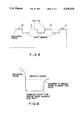
In the Step S8, only the finish stock within the groove closure is determined to be a groove finish machining section, as shown in FIG. 7A.
In the Step S9, the whole of the finish stock including the portions within and outside the groove closure is determined to be a groove finish machining section, as shown in FIG. 7B.
In the Step S10, the length of the groove closure (hereinafter referred to as "groove width") is compared with a predetermined single groove width maximum β. If the groove width is equal to or greater than the single groove width maximum, it is determined that it is appropriate to form a machining step using a tool having a width smaller than the groove width, and the process proceeds to the Step S12. If the groove width is smaller than the single groove width maximum, the process proceeds to the Step S11.
In the Step S11, an examination is made to determine whether or not there is any element other than end surface and longitudinal elements, e.g., rounding or chamfer, such as the one shown in FIG. 8, remote from the end points of the groove machining shape elements within the groove closure. If there is some element other than the end surface and longitudinal elements, it is determined that it is appropriate to form a machining step using a tool having a width smaller than the groove width, and the process proceeds to the Step S12. If there is no element other than the end surface and longitudinal elements, it is determined that it is appropriate to form a machining step using a tool having a width equal to the groove width for machining of both the groove width and the shape, and the process proceeds to the Step S16. In the Step S12, a kind of step for wide groove roughing is determined, this kind of step and the machining section determined in the Step S6 are stared in a temporary memory 4, and the process proceeds to the Step S13.
In the Step S13, a kind of step for wide groove finishing is determined, and this kind of step and the machining section determined in the Step S8 or S9 are stored, in the temporary memory 4, and the process proceeds to the Step S14.
In the Step S14, the groove width is compared with a predetermined large groove width decision value γ. If the groove width is equal to or greater than the large groove width decision value, the time when this rough groove machining step is effected is changed to a time before a lathe finish machining step to avoid occurrence of finishing of a groove closure portion cut off through an unnecessarily long distance. If the groove width is smaller than the large groove width decision value, it is determined that the distance of unnecessary finishing is substantially small, and the process proceeds to the Step S18 without changing the machining step order.
In the Step S16, a kind of step for simple groove roughing is determined, and this kind of step and the machining section determined in the Step S6 are stored in the temporary memory 4, and the process proceeds to the Step S17.
In the Step S17, a kind of step for simple groove finishing is determined, and this kind of step and the machining section determined in the Step S8 or S9 are stored in the temporary memory 4, and the process proceeds to the Step S18.
In the Step S18, the groove machining sections determined in the Step S6, S8 and S9 are removed from the groove machining area to update the groove machining area, and the process returns to the Step S4 to repeat the above-described operations.
Thereafter, the processor 1 forms the control information for the groove machining based on the information on the kinds of step and the machining sections stored in the temporary memory 4 and the information on machining conditions and kinds of tool obtained from information previously stored in parameter memory 7 or automatically determined by the processor 1, and stores this numerical control information in a numerical control information memory 8. The operator can perform the desired groove machining by using the numerical control information stored in the numerical control information memory 8. In the above-described process, a lathe machining step may be formed after execution of the Steps S1 to S3, and the Steps S4 to S8 may thereafter be executed, thereby determining the machining order and machining area sections while optimizing matching between groove machining steps and lathe machining step.
As described above, in the method for determining a groove machining process based on the numerical control information generating functions in accordance with this invention, the kinds of steps, the step order and the machining area sections can be automatically determined according to the shape of groove shape elements and characteristics of adjacent shape elements even if the groove machining method is examined by the operator before data input. It is thereby possible even for a person unskilled in groove machining to easily determine the groove machining method and to enable a substantial reduction in the number of overall process steps.
It should be understood that many modifications and adaptations of the invention will become apparent to those skilled in the art and it is intended to encompass such obvious modifications and changes in the scope of the claims appended hereto.

Claims (6)

What is claimed is:
1. A method for determining a groove machining process based on numerical control information generating functions of inputting a shape of a blank to be worked and a shape of a machining and generating the numerical control information from the blank shape and the machining shape, said method comprising the steps of:
extracting shape elements designated to be processed by groove machining; and
automatically determining kinds of step, step order and machined area for the groove machining based on the shapes of the groove shape elements and characteristics of other adjacent shape elements;
wherein, if the width of a machining shape element of the groove shape elements is equal to or greater than a predetermined value, a wide groove machining step using a tool having a width smaller than the width of the machining shape element is provided as a kind of step for the groove machining, or, if the width of the machining shape element is smaller than the predetermined value, a simple groove machining step using a tool having a width equal to the width of the machining shape element is provided as a kind of step for the groove machining.
2. A method for determining a groove machining process based on numerical control information generating functions of inputting a shape of a blank to be worked and a shape of a machining and generating the numerical control information from the blank shape and the machining shape, said method comprising the steps of:
extracting shape elements designated to be processed by groove machining; and
automatically determining kinds of step, step order and machined area for the groove machining based on the shapes of the groove shape elements and characteristics of other adjacent shape elements;
wherein, if there is a rounding element or a chamfer element among machining shape elements of the groove shape elements, a wide groove step is provided as a kind of step for the groove machining, or, in the absence of a rounding or chamfer element among the machining shape elements, a simple groove step is provided as a kind of step for the groove machining.
3. A method for determining a groove machining process based on numerical control information generating functions of inputting a shape of a blank to be worked and a shape of a machining and generating the numerical control information from the blank shape and the machining shape, said method comprising the steps of:
extracting shape elements designated to be processed by groove machining; and
automatically determining kinds of step, step order and machined area for the groove machining based on the shapes of the groove shape elements and characteristics of other adjacent shape elements;
wherein, if the width of a machining shape element of the groove shape elements is equal to or greater than a predetermined value, it is determined that the width of the machining shape element is so large that a distance of unnecessary lathe machining in finish machining is long, and the time when a step of rough groove machining shape elements is to be effected is set to be before the finish machining.
4. A method for determining a groove machining process based on numerical control information generating functions of inputting a shape of a blank to be worked and a shape of a machining and generating the numerical control information from the blank shape and the machining shape, said method comprising the steps of:
extracting shape elements designated to be processed by groove machining; and
automatically determining kinds of step, step order and machined area for the groove machining based on the shapes of groove shape elements and characteristics of other adjacent shape elements;
wherein at least one of machining shape elements adjacent to the machining shape elements of the groove shape elements is an object of lathe machining and if the groove machining shape elements have two end points and if the coordinate values of the two end points of the groove machining shape elements in a direction of groove working depth do not coincide with each other, a region surrounded by the groove shape elements and a line which is the perpendicular to one of the end points having the coordinate value closer to a groove bottom in a direction of groove machining depth on the groove machining shape element corresponding to the other end point remote from the groove bottom is set as an area to be rough machined.
5. A method for determining a groove machining process based on numerical control information generating functions according to claim 4, wherein, if the length of a portion of a machining shape element of the groove machining elements located outside the area to be rough machined is equal to or longer than a predetermined value, the portion of the groove shape element is set as an area to be machined by lathe finish machining, or if the length of the machining shape element portion is smaller than a predetermined shape, the portion of the groove shape element is included in the area to be machined by groove finishing.
6. A method for determining a groove machining process based on numerical control information generating functions of inputting a shape of a blank to be worked and a shape of a machining and generating the numerical control information from the blank shape and the machining shape, said method comprising the steps of:
extracting shape elements designated to be processed by groove machining; and
automatically determining kinds of step, step order and machined area for the groove machining based on the shapes of the groove shape elements and characteristics of other adjacent shape elements;
wherein, if the groove shape elements are designated to be processed to form a plurality of grooves having equal shapes and are arranged at equal intervals based on a single groove shape definition, the surface finish of machining shape elements between shift machining groove elements is set to one of the surface finishes of other machining shape elements located outside the group of groove machining shape elements, and wherein one of the surface finishes is higher in accuracy than the other surface finishes.
US07/623,620 1989-12-13 1990-12-07 Method for determining groove machining process based on numerical control information generating function Expired - Fee Related US5239478A (en)

Applications Claiming Priority (2)

Application Number Priority Date Filing Date Title
JP1323313A JPH084992B2 (en) 1989-12-13 1989-12-13 Grooving method decision method in numerical control information creation function
JP1-323313 1989-12-13

Publications (1)

Publication Number Publication Date
US5239478A true US5239478A (en) 1993-08-24

Family

ID=18153394

Family Applications (1)

Application Number Title Priority Date Filing Date
US07/623,620 Expired - Fee Related US5239478A (en) 1989-12-13 1990-12-07 Method for determining groove machining process based on numerical control information generating function

Country Status (2)

Country Link
US (1) US5239478A (en)
JP (1) JPH084992B2 (en)

Cited By (2)

* Cited by examiner, † Cited by third party
Publication number Priority date Publication date Assignee Title
CN101776885B (en) * 2010-01-07 2011-10-19 上海维宏电子科技有限公司 Method for automatically setting graphics processing sequence applied in numerical control system
US20220365520A1 (en) * 2019-06-26 2022-11-17 Siemens Aktiengesellschaft Geometric model-based evaluation method, system, and apparatus for kpi in production procedure

Families Citing this family (2)

* Cited by examiner, † Cited by third party
Publication number Priority date Publication date Assignee Title
JP2765782B2 (en) * 1992-04-24 1998-06-18 オークマ株式会社 How to create control information for processing grooves
JP5983268B2 (en) * 2012-10-03 2016-08-31 株式会社豊田中央研究所 Machining process decision device, machining process decision program, and machining process decision method

Citations (9)

* Cited by examiner, † Cited by third party
Publication number Priority date Publication date Assignee Title
US4530046A (en) * 1982-03-23 1985-07-16 Toyoda Koki Kabushiki Kaisha Method of inputting machining information to a machine tool numerical controller and apparatus therefor
US4669041A (en) * 1983-04-22 1987-05-26 Fanuc Limited Blank profile specifying method
US4723203A (en) * 1983-12-14 1988-02-02 Fanuc Ltd. Automatic machining process determination method in an automatic programming system
US4855898A (en) * 1985-12-10 1989-08-08 Fanuc Ltd NC data creation method
US4926311A (en) * 1987-02-20 1990-05-15 Fanuc Ltd. Part profile input method
US4942350A (en) * 1987-08-26 1990-07-17 Masaki Seki Method of creating NC data for grooving
US5089950A (en) * 1987-12-17 1992-02-18 Fanuc Ltd Part profile input method
US5099432A (en) * 1988-08-31 1992-03-24 Kabushiki Kaisha Okuma Tekkosho Method for determining machining process in numerical control information generating function
US5172327A (en) * 1988-01-11 1992-12-15 Fanuc Ltd. Automatic programming method

Family Cites Families (1)

* Cited by examiner, † Cited by third party
Publication number Priority date Publication date Assignee Title
JPS60127946A (en) * 1983-12-14 1985-07-08 Fanuc Ltd Selection of tool for groove-cutting work in automatic programming

Patent Citations (9)

* Cited by examiner, † Cited by third party
Publication number Priority date Publication date Assignee Title
US4530046A (en) * 1982-03-23 1985-07-16 Toyoda Koki Kabushiki Kaisha Method of inputting machining information to a machine tool numerical controller and apparatus therefor
US4669041A (en) * 1983-04-22 1987-05-26 Fanuc Limited Blank profile specifying method
US4723203A (en) * 1983-12-14 1988-02-02 Fanuc Ltd. Automatic machining process determination method in an automatic programming system
US4855898A (en) * 1985-12-10 1989-08-08 Fanuc Ltd NC data creation method
US4926311A (en) * 1987-02-20 1990-05-15 Fanuc Ltd. Part profile input method
US4942350A (en) * 1987-08-26 1990-07-17 Masaki Seki Method of creating NC data for grooving
US5089950A (en) * 1987-12-17 1992-02-18 Fanuc Ltd Part profile input method
US5172327A (en) * 1988-01-11 1992-12-15 Fanuc Ltd. Automatic programming method
US5099432A (en) * 1988-08-31 1992-03-24 Kabushiki Kaisha Okuma Tekkosho Method for determining machining process in numerical control information generating function

Cited By (2)

* Cited by examiner, † Cited by third party
Publication number Priority date Publication date Assignee Title
CN101776885B (en) * 2010-01-07 2011-10-19 上海维宏电子科技有限公司 Method for automatically setting graphics processing sequence applied in numerical control system
US20220365520A1 (en) * 2019-06-26 2022-11-17 Siemens Aktiengesellschaft Geometric model-based evaluation method, system, and apparatus for kpi in production procedure

Also Published As

Publication number Publication date
JPH084992B2 (en) 1996-01-24
JPH03184740A (en) 1991-08-12

Similar Documents

Publication Publication Date Title
RU2331911C2 (en) Automatic programming method and automatic programming device
EP0166783B1 (en) Machining step determination method for automatic programming
US20080109097A1 (en) Machining step generating apparatus
US5099432A (en) Method for determining machining process in numerical control information generating function
EP0309589B1 (en) Method of inputting profile information on product
US5239478A (en) Method for determining groove machining process based on numerical control information generating function
JPH01180009A (en) Automatic programming system
US6957123B2 (en) Automatic programming apparatus
US5471394A (en) Method for defining machining areas of a workpiece
US5113050A (en) Method of creating coreless-machining nc data for wire cut electric discharge machining
US5107414A (en) Method for determining a machining method in numerical control information generating apparatus
JPH0475850A (en) Tool selecting method fro dialogue type numerical control device
JP2753365B2 (en) How to create numerical control information
EP0165999A1 (en) Tool-selecting method for automatic programming
US5251145A (en) Decision apparatus for machining steps of numerical control information generating function
EP0148947A1 (en) Data input method
JPS60127946A (en) Selection of tool for groove-cutting work in automatic programming
JPH06335840A (en) Working condition setting system
US5184294A (en) Apparatus for generating numerical control information for machining parts
JPH05228786A (en) Automatic generating device for nc data in nc machine tool
JPS63148306A (en) Generation system for groove-shaped tool course in numerically controlled lathe
JPH07117848B2 (en) How to determine the inner diameter machining method in the numerical control information creation function
JPH06149334A (en) Automatic nc data generation system
JPH0751988A (en) Nc data automatic producing device
JPH079605B2 (en) Automatic interference check method in automatic programming

Legal Events

Date Code Title Description
AS Assignment

Owner name: KABUSHIKI KAISHA OKUMA TEKKOSHO, JAPAN

Free format text: ASSIGNMENT OF ASSIGNORS INTEREST.;ASSIGNORS:YAMAMOTO, KYOICHI;ITO, KENJI;TOMITA, HIROKI;REEL/FRAME:005534/0093

Effective date: 19901112

FEPP Fee payment procedure

Free format text: PAYOR NUMBER ASSIGNED (ORIGINAL EVENT CODE: ASPN); ENTITY STATUS OF PATENT OWNER: LARGE ENTITY

FPAY Fee payment

Year of fee payment: 4

FEPP Fee payment procedure

Free format text: PAYOR NUMBER ASSIGNED (ORIGINAL EVENT CODE: ASPN); ENTITY STATUS OF PATENT OWNER: LARGE ENTITY

Free format text: PAYER NUMBER DE-ASSIGNED (ORIGINAL EVENT CODE: RMPN); ENTITY STATUS OF PATENT OWNER: LARGE ENTITY

FPAY Fee payment

Year of fee payment: 8

REMI Maintenance fee reminder mailed
LAPS Lapse for failure to pay maintenance fees
STCH Information on status: patent discontinuation

Free format text: PATENT EXPIRED DUE TO NONPAYMENT OF MAINTENANCE FEES UNDER 37 CFR 1.362

FP Lapsed due to failure to pay maintenance fee

Effective date: 20050824