BACKGROUND OF THE INVENTION
This invention relates to storage containers and particularly to storage containers for holding one or more articles to be protected for very long periods of time. Such storage containers sometimes are referred to as time capsules.
To preserve materials and artifacts of the present such as documents, film, books, fine art, models and the like, for future generations and ages, special receptacles are stocked with such materials and artifacts and placed in special locations for protection until some future date when the receptacle is to be opened and its contents examined. Such receptacles typically are sealed to protect their contents from the distructive effects of moisture, and are stored in special vaults, or buried, for protection against physical damage by crushing, explosion or the like.
The basic requirements for such a container are that it be physically strong, air-tight, waterproof, and made from materials that will not cause damage to the contents. Materials used for the containers typically are copper, aluminum, stainless steel or plastic and the containers are provided with seals or gaskets, or are welded closed, for air- and water-tightness.
Unfortunately, apart from stainless steel, metals that have been used are subject to a relatively high level of corrosion over time, including electrolysis and rust, and plastics either deteriorate or release acids or other damaging chemicals into the container over long periods of time, or become waterpermeable. Further, conventional seal materials also deteriorate with time, losing their resilience and water-tightness. Conventional soldering and welding materials either deteriorate or introduce contaminants into the container, so seals formed by soldering and welding have disadvantages.
The foregoing prior approaches to the art of preparing time capsules have resulted in serviceable but less-than-optimum long-term storage containers. The objective of this invention is to provide a substantially improved storage container that is capable of increasing the protection of materials and artifacts for substantially greater periods of time.
SUMMARY OF THE INVENTION
The present invention provides an improved long-term storage container in which all of the components are composed of highly durable and heat- and corrosion-resistant materials and are tightly sealed in a manner that will remain effective for much longer than has been the case in the past, probably for thousands of years. The structure of the container provides physical protection against shock and crushing, avoids electrolysis and contamination of the interior by its components, and permits the ready substitution of an inert atmosphere for the original atmosphere of the container, air, after the articles to be stored are in place. All of this significantly increases the degree and duration of protection provided by the container.
More specifically, and as illustrated by the preferred embodiment shown herein, the present invention comprises an outer storage container including a receptacle and a cover composed of the same highly corrosion-resistant and relatively strong metal, preferably stainless steel or titanium, and sealed by a highly corrosion-resistant and very malleable metal seal, preferably one of the precious metals--gold, platinum or silver--clamped between the cover and the receptacle. Replacement of the gaseous atmosphere is accomplished through at least one valve having a body composed of the corrosion-resistant metal and a closure member of inert material, preferably ceramic, sealed after use by a corrosion resistant back-up plug, preferably with a precious metal seal. Additional sealing protection is provided by a secondary cover of the same corrosion-resistant metal which overlies the primary cover and has a flange that is bonded to the receptacle by an external welded seal, also of corrosion-resistant material, the flange having a thin-wall section that can be cut with a sharp knife for removal of the secondary cover without breaking the welded seal. Extra physical protection is provided by an inner container smaller than the outer container and disposed within the latter with special cushioning means between the two, herein sets of resiliently flexible internal protrusions on the outer container and external protrusions on the inner container, in abutting engagement between the containers. The illustrative inner container is titanium and the protrusions are sets of parallel ribs of arcuate cross-sectional shape disposed substantially at right angles to each other. Non-reactive archival storage paper also may be used for the inner container, and may be used to separate metal parts from each other.
Other features and advantages of the invention will become apparent from the following detailed description, taken in conjunction with the accompanying drawings.
BRIEF DESCRIPTION OF THE DRAWINGS
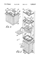
FIG. 1 is a perspective view of a long-term storage container embodying the novel features of the present invention;
FIG. 2 is an exploded perspective view of the storage container of FIG. 1;
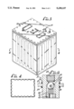
FIG. 3 is an enlarged perspective view of the storage container of FIG. with the secondary cover removed;
FIG. 4 is a cross-sectional view taken along line 4--4 of FIG. 3, shown on a reduced scale;
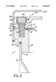
FIG. 5 is a greatly enlarged fragmentary cross-sectional view taken along the line 5--5 of FIG. 1; and
FIG. 6 is a greatly enlarged fragmentary cross-sectional view taken along the line 6--6 of FIG. 3.
DETAILED DESCRIPTION OF THE PRESENTLY PREFERRED EMBODIMENT
As shown in the drawings for purposes of illustration, the invention is embodied in a long-term storage container, indicated generally by the reference number 10 in FIGS. 1 and 2, for holding and protecting one or more articles (not shown) over a long period of time. The illustrative storage container basically comprises an outer storage receptacle 11 and a cover 12 for the receptacle, both composed of the same relatively strong and highly corrosion-resistant metal to provide structural protection and to avoid damage from corrosion or electrolysis, and a seal between the cover and the receptacle formed by a seal ring 13 composed of highly corrosion-resistant and very malleable metal that is clamped between opposed sealing surfaces 14 and 15 of the receptacle and the cover, herein by means of a series of headed fasteners 17 (FlG. 5) extending through holes 18 in the cover and secured to the receptacle. The fasteners are bolts threaded into holes 19 in the sealing surface 14. A secondary cover 20 provides extra sealing protection for the container 10, and a second, inner container 21 provides extra physical protection for articles in the container, both the secondary cover and the inner container being composed of the same corrosion-resistant metal as the outer receptacle 11 and its cover 12, or a non-reactive material such as archival storage paper.
The preferred material for the outer and inner containers is material selected from the group consisting of stainless steel and titanium, both of which have the desired heat and corrosion resistance and strength. Titanium is used in the preferred embodiment of the invention. The preferred material for the seal ring 13 is a material selected from the group consisting of gold, platinum and silver (ninety-nine percent pure or fine silver), which have the necessary malleability and corrosion resistance. Silver is used in the preferred embodiment.
As best seen in FIGS. 2 and 3, the outer storage receptacle 11 is formed in three pieces, a dished titanium bottom wall 23 that is rectangular for the preferred rectangular box-like container with an upturned, integral side flange 24 around its periphery, a sidewall 25 and a top rim 27. The sidewall 25 is formed in one piece, as an elongated titanium panel that is bent into a rectangular shape, wrapped around the bottom wall and bonded together at its ends with a weld, a titanium weld in the preferred embodiment.
The top rim 27, shown in FIGS. 2 and 5, is rectangular in shape and has a depending neck 28 that is fitted tightly inside the sidewall 25, with an interference fit facilitated by a beveled outer corner 29 (FIG. 5) of the neck, an outer side 30 offset outwardly from the sidewall, and a top side 24 that faces upwardly toward the cover 12 and forms the sealing surface of the receptacle 11. A continuous seal groove 32 is formed in this surface and surrounds the opening into the receptacle that is defined by the rim, and the series of threaded bolt holes 19 is formed in this surface, spaced outwardly from the seal groove 32, on the side thereof opposite the opening into the receptacle. A continuous titanium weld 36 (FIG. 5) is applied between the neck 28 and the sidewall 25 to insure a tight seal.
The primary cover 12 is formed as a one-piece plate of the same size and exterior shape as the rim 27, and overlies the latter with its outer side 33 aligned with the outer side 30 of the rim. The clamping bolts 17 extend through the holes 18, which are closely spaced in a series around the periphery of the cover and preferably have countersunk outer ends 34 for heads 35 on the bolts, and are threaded into the holes 19 in the rim.
It will be seen in FIG. 5 that the seal ring 13 (which originally is substantially circular in cross-section) has a larger cross-sectional area than the seal groove 32, so as to extend substantially above the top surface of the rim after being pressed and deformed into the groove by the clamping action of the bolts 17. This leaves the cover and the rim spaced apart as shown in FIG. 5, with the space securely sealed by the seal ring.
Substitution of an inert atmosphere for the original atmosphere in the container 10 is accomplished by means of one or more valves 37 (FIGS. 2, 3 and 6) that permit evacuation of the original atmosphere and insertion of an inert gas, preferably argon, and thereafter maintain a tight seal for the container. As best seen in FIG. 6, each valve comprises a body 38 held in the cover 12 by titanium welds 39, a corrosion-resistant closure herein in the form of a ceramic ball 40, a titanium spring 41 inwardly from the ball urging it yieldable against a seat 42, and a titanium inner plug 43 loading the spring and having a central passage to the interior. With the ball held open from the outside, the original atmosphere is exhausted and the argon gas is inserted. After the ball is released, an outer back-up plug 44, also of titanium, and a precious metal seal 45 are inserted in the cover to back up the valve and provide back-up seals in the cover. Two such valves 37 are included in the illustrative storage container.
The titanium secondary cover 20 is formed in one piece and has a flat top wall 47 spaced above the primary cover 12 and an integral depending flange 48 which is long enough to extend across the outer sides 30 and 33 of the primary cover and the receptacle rim 27. This flange is sized and shaped for tight-fitting engagement with these sides, and is bonded to the rim by a titanium weld 49 (FIG. 5), which securely seals the secondary cover in place. To eliminate air from the secondary cover, it preferably is filled with argon gas in an inverted position before being assembled in an inverted position, argon gas being heavier than air.
To facilitate eventual removal of the secondary cover 20 without danger of damage to the contents of the storage container 10, a thin-wall section 50 is formed in the flange 48 above the weld 49, with a reduced thickness of titanium thin enough to be cut with a sharp tool such as a knife (not shown). This section can be formed by removing metal from the outside in a milling operation, forming an external groove in the flange, leaving a reduced thickness of metal that is preferably less than one millimeter, and as thin as 250 micrometers. As shown in FIG. 5, the thin-wall section is aligned with an internal groove inside the flange, formed by two beveled edges 51 and 52 on the primary cover 12 and the receptacle rim 27. This provides clearance for the cutting tool.
The illustrative inner protective container, indicated generally by the number 21, is shown in FIGS. 2 and 4 and comprises a box-like inner receptacle 53 having an open upper side, and a cover 54 in the form of a plate that is slidable into a closed position on top of the inner receptacle, being held in place thereon by two guides 55 that are bent to curve over the opposite edges of the cover and retain it loosely in place on the receptacle. No sealing is required of this cover, since its function is to provide only structural protection for the contents of the storage container 10. This inner container may be titanium or other non-reactive material.
For this purpose, the inner container 21 is made smaller than the outer receptacle 11, and cushioning means are provided around the inner container, herein in the form of outwardly projecting resiliently flexible protrusions 57 formed integrally with the walls and cover of the inner container and inwardly projecting, resiliently flexible protrusions 58 formed integrally with the sidewall and the bottom wall of the outer receptacle 11. As shown in FIGS. 2 and 4, these protrusions 57 and 58 are elongated ribs of arcuate cross-sectional shape, herein substantially semi-circular, that extend substantially the full lengths of the walls in which they are formed, and two shorter ribs 59 in the inner cover 54. The ribs of the various sets are parallel to each other, and are arranged at angles, preferably of about ninety degrees, with the ribs of the opposing sets. The ribs 57 and 59 of the inner cover abut against the underside of the outer cover 12. When deformed out of relatively thin sheet metal, such as titanium 0.080 of an inch thick, the ribs have sufficient resilient strength to provide good cushioning protection for the contents. Additional special fixtures (not shown) may be provided inside the inner container to receive and hold the articles to be protected.
From the foregoing, it will be evident that the present invention provides an effective long-term storage container for use as a time capsule that will preserve articles for a long period of time, extending into the thousands of years. It also will be apparent to those skilled in the art that the use of titanium or stainless steel containers filled with inert gas and sealed with a malleable precious metal seal will provide high heat resistance as well as corrosion resistance. It also will be evident that, while one specific embodiment has been shown and described in detail, various modifications and changes may be made by those skilled in the art within the spirit and scope of the invention.