US5225669A - Sensor system with adjustment for ambient conditions - Google Patents
Sensor system with adjustment for ambient conditions Download PDFInfo
- Publication number
- US5225669A US5225669A US07/772,940 US77294091A US5225669A US 5225669 A US5225669 A US 5225669A US 77294091 A US77294091 A US 77294091A US 5225669 A US5225669 A US 5225669A
- Authority
- US
- United States
- Prior art keywords
- unit
- sensor
- output
- sensor system
- reception signal
- Prior art date
- Legal status (The legal status is an assumption and is not a legal conclusion. Google has not performed a legal analysis and makes no representation as to the accuracy of the status listed.)
- Expired - Fee Related
Links
Images


Classifications
-
- B—PERFORMING OPERATIONS; TRANSPORTING
- B60—VEHICLES IN GENERAL
- B60S—SERVICING, CLEANING, REPAIRING, SUPPORTING, LIFTING, OR MANOEUVRING OF VEHICLES, NOT OTHERWISE PROVIDED FOR
- B60S1/00—Cleaning of vehicles
- B60S1/02—Cleaning windscreens, windows or optical devices
- B60S1/04—Wipers or the like, e.g. scrapers
- B60S1/06—Wipers or the like, e.g. scrapers characterised by the drive
- B60S1/08—Wipers or the like, e.g. scrapers characterised by the drive electrically driven
- B60S1/0818—Wipers or the like, e.g. scrapers characterised by the drive electrically driven including control systems responsive to external conditions, e.g. by detection of moisture, dirt or the like
- B60S1/0822—Wipers or the like, e.g. scrapers characterised by the drive electrically driven including control systems responsive to external conditions, e.g. by detection of moisture, dirt or the like characterized by the arrangement or type of detection means
- B60S1/0833—Optical rain sensor
-
- G—PHYSICS
- G01—MEASURING; TESTING
- G01S—RADIO DIRECTION-FINDING; RADIO NAVIGATION; DETERMINING DISTANCE OR VELOCITY BY USE OF RADIO WAVES; LOCATING OR PRESENCE-DETECTING BY USE OF THE REFLECTION OR RERADIATION OF RADIO WAVES; ANALOGOUS ARRANGEMENTS USING OTHER WAVES
- G01S17/00—Systems using the reflection or reradiation of electromagnetic waves other than radio waves, e.g. lidar systems
- G01S17/02—Systems using the reflection of electromagnetic waves other than radio waves
- G01S17/04—Systems determining the presence of a target
-
- G—PHYSICS
- G01—MEASURING; TESTING
- G01V—GEOPHYSICS; GRAVITATIONAL MEASUREMENTS; DETECTING MASSES OR OBJECTS; TAGS
- G01V8/00—Prospecting or detecting by optical means
- G01V8/10—Detecting, e.g. by using light barriers
-
- G—PHYSICS
- G01—MEASURING; TESTING
- G01S—RADIO DIRECTION-FINDING; RADIO NAVIGATION; DETERMINING DISTANCE OR VELOCITY BY USE OF RADIO WAVES; LOCATING OR PRESENCE-DETECTING BY USE OF THE REFLECTION OR RERADIATION OF RADIO WAVES; ANALOGOUS ARRANGEMENTS USING OTHER WAVES
- G01S7/00—Details of systems according to groups G01S13/00, G01S15/00, G01S17/00
- G01S7/48—Details of systems according to groups G01S13/00, G01S15/00, G01S17/00 of systems according to group G01S17/00
- G01S7/483—Details of pulse systems
- G01S7/484—Transmitters
-
- G—PHYSICS
- G01—MEASURING; TESTING
- G01S—RADIO DIRECTION-FINDING; RADIO NAVIGATION; DETERMINING DISTANCE OR VELOCITY BY USE OF RADIO WAVES; LOCATING OR PRESENCE-DETECTING BY USE OF THE REFLECTION OR RERADIATION OF RADIO WAVES; ANALOGOUS ARRANGEMENTS USING OTHER WAVES
- G01S7/00—Details of systems according to groups G01S13/00, G01S15/00, G01S17/00
- G01S7/48—Details of systems according to groups G01S13/00, G01S15/00, G01S17/00 of systems according to group G01S17/00
- G01S7/483—Details of pulse systems
- G01S7/486—Receivers
Abstract
A sensor system for recording the ambient conditions of an optical sensor having a transmitter unit and a receiver unit linked by an optical gap. An electronic sensor unit is provided that predetermines a basic setting of the optical sensor independent of the ambient conditions. The electronic sensor unit contains a signal processing section with comparators for comparing a reception signal of the optical sensor with threshold values corresponding to certain ambient conditions. The electronic sensor unit recognizes and evaluates changes in the ambient conditions as a function of the comparing, and restores the basic setting of the optical sensor such that the sensor system dependably reacts to subsequent changes in the ambient conditions.
Description
1. Field of the Invention
The invention relates to the field of optical sensors.
2. Background Information
Optical sensors in sensor systems contain a transmitter unit and a receiver unit linked to one another via an optical distance. Changes in the ambient conditions of the sensor can lead to a change in the optical distance and hence to a variation in the reception signal that can be detected and processed by an evaluation unit of the sensor system. In motor vehicles, for example, the changes in the optical properties caused by precipitation on the windshield can be registered by a sensor system, and the windshield wipers can be actuated.
To permit dependable recording of changes in the optical properties, the sensor system must be set to a defined initial value--for example by predetermining the transmission current or by adjusting the evaluation circuit. When the sensor system is used under changed ambient conditions--in the above example of the precipitation sensor with a different windshield type being used--the sensitivity of the optical sensor must be adjusted to the changed optical properties. To do so, either the amplification of the transmitter or that of the receiver must be varied by manual adjustment. In the case of frequently changing ambient conditions, this is very expensive for series production and entails high costs, since for every intended application a correspondingly adjusted system must be provided.
The object underlying the invention is to provide an optical sensor system that can be used for all different ambient conditions without adjustment problems.
This object is attained in accordance with the invention by a sensor system for recording the ambient conditions of an optical sensor having a transmitter unit and a receiver unit linked by an optical gap. An electronic sensor unit is provided that predetermines a basic setting of the optical sensor independent of the ambient conditions. The electronic sensor unit contains a signal processing section with comparators for comparing a reception signal of the optical sensor with threshold values corresponding to certain ambient conditions. The electronic sensor unit contains means for recognizing and evaluating changes in the ambient conditions as a function of the comparing and for restoring the basic setting of the optical sensor such that the sensor system dependably reacts to subsequent changes in the ambient conditions.
Advantageous embodiments of the invention are described below.
In one embodiment, the signal processing section of the electronic sensor unit has in addition to the comparators a pulse oscillator and a first logic stage. The electronic sensor unit has a logic section having a second and third logic stage and a first and second counter used for setting the amplitude of a transmission current of a transmitter element of the transmitter unit and for evaluation, and a digital-to-analog converter is provided for predetermining the amplitude of the transmission current of the transmitter element of the transmitter unit.
In another embodiment, a fixed basic value is predetermined for the reception signal of the receiver unit for basic setting of the optical sensor independently of the ambient conditions. The digital-to-analog converter has an input connected both to the first counter and to the first logic stage, and is first set to a maximum value by the first logic stage and then reduced by the second logic stage and the first counter until the reception signal fails to attain a first threshold value determined by a first one of the comparators which is connected to an output of the receiver unit.
In another embodiment, at least a first and second of the comparators of the signal processing section have inputs connected to an output of the receiver unit, have different threshold values, and emit different output signals. The third logic stage has inputs connected to an output of the second counter and an output of the first logic stage, and registers and evaluates the absence of comparator output signals when the different threshold values are not attained by the reception signal.
In another embodiment, an evaluation unit is connected to an output of the third logic stage and triggers a reaction, depending on the comparator output signals, by way of a control unit connected to the evaluation unit. A failure by the reception signal to attain respective different comparator threshold values is variously evaluated by the evaluation unit and leads to respective different reactions by the control unit.
In a further embodiment, after failure by the reception signal to attain different comparator threshold values, the basic setting of the optical sensor is restored by the logic section. This restoring process differs depending on which respective threshold value is not attained.
In another embodiment, the second logic stage is connected to an output of the first comparator and provides an output to the first counter. The second logic stage operates the first counter to count upwards when the reception signal fails to attain a second comparator threshold value so that the amplitude of the transmission current of the transmitter element is increased by the digital-to-analog converter until the reception signal attains a first threshold value.
In another embodiment, the first logic stage is connected to the output of a third comparator and sets the digital-to-analog converter, and hence the amplitude of the transmission current of the transmitter element, to a maximum value when the reception signal fails to attain a third comparator threshold value.
In a further embodiment, the optical sensor is operated with an AC voltage signal. An output of the receiver unit is connected to the pulse oscillator which generates a periodic pulse sequence.
In yet another embodiment, the comparators supply output pulses of varying number and direction depending on the reception signal. Evaluation by the evaluation unit and the reaction of the control unit depend on the number and duration of the comparator output pulses.
In a further embodiment, the system is used as a precipitation sensor system for control of a windshield wiper system in a motor vehicle subject to differing degrees of wetting of the windshield.
The optical sensor system in accordance with the invention can be used in a single design type or with a single fixed setting of its basic sensitivity for all different ambient conditions. The sensor system is automatically adjusted for applications in various ambient conditions by predetermining a fixed value for the receiver current regardless of the ambient conditions when performing the basic setting of the sensor system. To do so, the amplitude of the transmission current is initially increased to a maximum value and then successively reduced until a threshold value determined by the basic receiver current is attained.
In the event of a change in the optical properties in the vicinity of the sensor, the optical link between the transmitter and the receiver is disturbed and the current detected by the receiver unit reduced accordingly. This is evaluated by an electronic sensor unit using further threshold value switches, and if necessary an appropriate reaction by the sensor system is triggered. When the reaction of the system has ended, the sensor is reset to its basic setting by further switching means so that it can dependably record subsequent further changes in the ambient conditions.
The optical sensor system is preferably operated in the AC voltage mode, with the electronic sensor unit generating and evaluating pulses of different length and width depending on the ambient conditions.
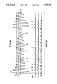
FIG. 1 shows a block diagram of an optical sensor system, FIGS. 2a and 2b the timing of the signals at various points in the circuit diagram, and FIG. 3 the layout of a digital precipitation sensor system.
According to FIG. 1, the sensor system consists of the optical sensor 10, 20, the evaluation unit 30, and the control unit 40, with the optical sensor containing the optical unit 10 and the electronic sensor unit 20.
The optical unit 10 consists of the transmitter unit 11 with a current source and transmitter element 14, the receiver unit 12 with receiver element 15 and a resonant circuit, and the optical distance 13 between the transmitter element 14 and the receiver element 15. The resonant circuit filters out of the frequency mixture emitted by the transmitter element 14 that signal corresponding to its resonance frequency; this signal is amplified and used to feed the transmitter element 14.
The electronic sensor unit 20 contains:
a signal processing section 21 with a pulse oscillator 101 that generates periodic clock pulses from the AC voltage signal, with the comparators 111, 112 and 113 used to determine threshold values during signal detection and to supply pulses of varying width depending on the set threshold value for control of the evaluation circuit, and with the first logic stage 121, which upon switch-on of the sensor system or in the event of failure to attain the lowest comparator threshold supplies an output pulse that is longer than a normal sensor pulse and that is used to control the evaluation and to set the amplitude of the transmission current,
a logic section 22 for setting the amplitude of the transmission current and for evaluation of the detected signal, with a first and a second counter 131, 132 and with a second and third logic stage 122, 123 and
a D/A converter 23 for controlling the amplitude of the transmission current.
The evaluation unit 30, for example a computer or microprocessor, recognizes the various pulse sequences and can trigger appropriate reactions of the control unit 40.
FIG. 2 shows the timing at various points of the circuit diagram according to FIG. 1; FIG. 2a shows the reception signal UE with the threshold values S1, S2 and S3 predetermined by the comparators 111 to 113, and FIG. 2b shows from top to bottom the signals at the output of comparators 111, 112 and 113 as well as the clock signal at the output of the pulse oscillator 101.
For determination of a defined initial value or for basic setting of the sensitivity of the optical sensor, the D/A converter 23 is set to the maximum value upon switch-on of the sensor system (time t1) by the first logic stage 112, so that the transmission current of the transmitter element predetermined by the value of the D/A converter 23, and hence the reception signal UE at the output of the receiver unit, assumes the maximum value (FIG. 2a) and thus exceeds the threshold value S1. At the output of the comparator 111, a pulse sequence occurs (FIG. 2b) that resets step by step, the D/A converter 23 actuated by the second logic stage 122 and the first counter 131 and so reduces the amplitude of the transmission current. This procedure is maintained and thus the reception signal UE too reduced until the switching threshold S1 of the first comparator 111 is attained (time t2). No further pulses occur at the output of comparator 111, and the sensor is set to a fixed basic sensitivity and is ready for detection with a transmission signal at a constant level.
If the optical properties change (time t3) in the vicinity of the optical sensor, the amplitude of the reception signal UE is reduced and the threshold value S2 predetermined by the comparator 112 is not attained, so that no further pulses occur at the output of the comparator 112. The second counter 132, which is normally repeatedly reset by the pulses at the output of the comparator stage 112, can therefore count up when these pulses do not come; this is recognized by the third logic stage 123 and processed by the evaluation unit 30. At the same time, counting up by the counter 132 increases both the first counter 131 too, and the amplitude of the transmission signal via the D/A converter 23, until the reception signal UE has again attained the switching threshold S1 and the sensor its basic setting (time t4).
In the case of different degrees of change in the signals as a result of different degrees of change in the ambient conditions of the optical sensor, it is often necessary for the sensor system to react or respond differently. For this purpose, the additional comparator 113 is provided, that in the event of a major change in the reception signal UE (time t5)--failure to attain comparator threshold S3 at time t6 --no longer supplies output pulses to the first logic stage 121. This is recognized and evaluated by the evaluation unit 30, and a faster and stronger reaction by the control unit 40 to the signal change is initiated. In order to restore the sensor responsiveness immediately after this major signal change, the transmission current is--as in the switch-on procedure--increased to its maximum value by the logic stage 123 and the D/A converter 23, and then reduced, as a result of which the sensor very quickly resumes its basic setting.
As an embodiment of a sensor system, FIG. 3 shows a precipitation sensor consisting of the optical sensor 10 operating in the infrared range, the electronic sensor unit 20, and the microprocessor 30. The precipitation sensor is intended to recognize wetting of the windshield 50 of a motor vehicle, caused by a film of moisture or by falling raindrops, for example, and to control the windshield wiper unit 40 depending on the degree of wetting or quantity of precipitation.
The precipitation sensor can be used for different windshield types 50--white glass, thermally insulating glass, anti-dazzle glass--having differing optical properties, with the windshield wiper unit 40 being controlled by the microprocessor 30 as a function of the moisture or the degree of wetness of the windshield 50--from slow interval wiping in the case of a moisture film or individual raindrops to fast continuous wiping action in the case of downpours or splash water. The precipitation sensor can be activated manually by operating a switch, which can if necessary be visually indicated; if the activated sensor does not detect any raindrops, a wiping operation can be automatically triggered after a defined and predeterminable time, for example 60 s.
The optical sensor 10 comprises, for example, an IR transmitter diode 11, a lens system 16, and an IR receiver diode 12, with the sensor being fastened to the inside of the windshield 50 and the lenses 16 being at an angle of 45° to the windshield 50. The change in the light reflected on the outside of the windshield 50 within the sensor range 17--as a result of the presence of water droplets--is picked up by the electronic sensor unit 20 and this reflection change is evaluated by the microprocessor 30. To exclude external light effects, AC voltages are used, their frequency being 50 kHz, for example. The sensor supplies an output pulse of defined width whose frequency depends on the degree of wetting or on the number of droplets recognized on the windshield.
For basic setting of the sensor 10, a fixed threshold value S1 --for example 700 mV--is predetermined for all different types of windshield 50. If individual raindrops hit the windshield 50, the reception signal is reduced and the comparator threshold value S2 is not attained; since the comparator threshold S3 is not fallen short of, slow control of the windshield wipers--for example after a settable reaction time--is predetermined. With large quantities of water on the windshield--for example splash water or persistent rain--the reception signal is reduced so much that the comparator threshold value S3 is not attained. This triggers an immediate operation of the windshield wipers; subsequent initialization of the sensor by predetermination of the basic setting restores the sensor system immediately to the responsive state.
A further application of the optical sensor system is, for example, detection of bubbles or impurities in liquids. For example, impurities or gas bubbles in coloured liquids inside pipes with continuous flow quantity cause signal changes that are recognized by the sensor.
Claims (10)
1. A sensor system for recording the ambient conditions of an optical sensor having a transmitter unit and a receiver unit linked by an optical gap,
wherein an electronic sensor unit is provided that predetermines a basic setting of said optical sensor independent of the ambient conditions,
wherein said electronic sensor unit contains a signal processing section with comparators for comparing a reception signal of said optical sensor with threshold values corresponding to certain ambient conditions,
wherein said electronic sensor unit contains means for recognizing and evaluating changes in the ambient conditions as a function of the comparing and for restoring the basic setting of said optical sensor such that the sensor system dependably reacts to subsequent changes in the ambient conditions,
wherein said signal processing section of said electronic sensor unit has in addition to said comparators a pulse oscillator and a first logic stage,
wherein said electronic sensor unit has a logic section having a second and third logic stage and a first and second counter used for setting the amplitude of a transmission current of a transmitter element of the transmitter unit and for evaluation, and
wherein a digital-to-analog converter is provided for predetermining the amplitude of the transmission current of the transmitter element of the transmitter unit.
2. A sensor system according to claim 1, wherein a fixed basic value is predetermined for the reception signal of said receiver unit for basic setting of said optical sensor independently of the ambient conditions, and wherein said digital-to-analog converter has an input connected both to said first counter and to said first logic stage, and is first set to a maximum value by said first logic stage and then reduced by said second logic stage and said first counter until said reception signal fails to attain a first threshold value determined by a first one of said comparators which is connected to an output of said receiver unit.
3. A sensor system according to claim 1, wherein at least a first and second of said comparators of said signal processing section have inputs connected to an output of said receiver unit, have different threshold values, and emit different output signals, and wherein the third logic stage has inputs connected to an output of said second counter and an output of said first logic stage, and registers and evaluates the absence of comparator output signals when said different threshold values are not attained by said reception signal.
4. A sensor system according to claim 3, wherein an evaluation unit is connected to an output of said third logic stage and triggers a reaction, depending on comparator output signals, by way of a control unit connected to said evaluation unit, and wherein a failure by said reception signal to attain respective different comparator threshold values is variously evaluated by said evaluation unit and leads to respective different reactions by said control unit.
5. A sensor system according to claim 4, wherein after failure by said reception signal to attain different comparator threshold values, the basic setting of the optical sensor is restored by said logic section, and wherein the restoring process differs depending on which respective threshold value is not attained.
6. A sensor system according to claim 5, wherein the second logic stage is connected to an output of the first comparator and provides an output to the first counter, and wherein said second logic stage operates said first counter to count upwards when said reception signal fails to attain a second comparator threshold value so that the amplitude of the transmission current of the transmitter element is increased by the digital-to-analog converter until said reception signal attains a first threshold value.
7. A sensor system according to claim 5, wherein the first logic stage is connected to the output of a third comparator and sets the digital-to-analog converter, and thereby the amplitude of the transmission current of the transmitter element, to a maximum value when said reception signal fails to attain a third comparator threshold value.
8. A sensor system according to claim 4, wherein said optical sensor is operated with an AC voltage signal, and wherein an output of said receiver unit is connected to said pulse oscillator which generates a periodic pulse sequence.
9. A sensor system according to claim 8, wherein the comparators supply output pulses of varying number and duration depending on the reception signal, and wherein evaluation by the evaluation unit and the reaction of the control unit depend on the number and duration of the comparator output pulses.
10. A sensor system according to claim 1, wherein said system is used as a precipitation sensor system for control of a windshield wiper system in a motor vehicle subject to differing degrees of wetting of the windshield.
Applications Claiming Priority (2)
| Application Number | Priority Date | Filing Date | Title |
|---|---|---|---|
| DE4036407 | 1990-11-15 | ||
| DE4036407A DE4036407C2 (en) | 1990-11-15 | 1990-11-15 | Sensor system |
Publications (1)
| Publication Number | Publication Date |
|---|---|
| US5225669A true US5225669A (en) | 1993-07-06 |
Family
ID=6418322
Family Applications (1)
| Application Number | Title | Priority Date | Filing Date |
|---|---|---|---|
| US07/772,940 Expired - Fee Related US5225669A (en) | 1990-11-15 | 1991-10-08 | Sensor system with adjustment for ambient conditions |
Country Status (4)
| Country | Link |
|---|---|
| US (1) | US5225669A (en) |
| EP (1) | EP0485857B1 (en) |
| JP (1) | JPH04299235A (en) |
| DE (1) | DE4036407C2 (en) |
Cited By (21)
| Publication number | Priority date | Publication date | Assignee | Title |
|---|---|---|---|---|
| US5313072A (en) * | 1993-02-16 | 1994-05-17 | Rockwell International Corporation | Optical detector for windshield wiper control |
| WO1996002858A1 (en) * | 1994-07-15 | 1996-02-01 | Baumer Electric Ag | Optical sensor with suppression of optical interference |
| WO1997031275A1 (en) * | 1996-02-22 | 1997-08-28 | Siemens Aktiengesellschaft | Method and device for detecting an object in a region to be monitored |
| US5872437A (en) * | 1995-05-27 | 1999-02-16 | Robert Bosch Gmbh | Device for operating a windshield wiper |
| US5896018A (en) * | 1996-01-19 | 1999-04-20 | Robert Bosch Gmbh | Device for operating a windshield wiper |
| EP0926512A1 (en) * | 1997-12-17 | 1999-06-30 | Inter Company Computer, Engineering, Design Services, in het kort : " Concept Design", naamloze vennootschap | Proximity detecting device |
| US6002229A (en) * | 1996-01-19 | 1999-12-14 | Robert Bosch Gmbh | Device for operating a windshield wiper |
| GB2341696A (en) * | 1998-09-15 | 2000-03-22 | Bosch Gmbh Robert | Apparatus for automatically activating a device in a motor vehicle |
| US6078056A (en) * | 1998-12-30 | 2000-06-20 | Libbey-Owens-Ford Co. | Moisture sensor with autobalance control |
| WO2000040934A1 (en) | 1998-12-31 | 2000-07-13 | Libbey-Owens-Ford Co. | Moisture sensor with automatic emitter intensity control |
| US6091065A (en) * | 1998-12-31 | 2000-07-18 | Libbey-Owens-Ford Co. | Moisture sensor with digital signal processing filtering |
| GB2355523A (en) * | 1999-10-21 | 2001-04-25 | Notetry Ltd | Infrared detection system |
| EP1113260A3 (en) * | 1999-12-28 | 2002-05-22 | Nippon Sheet Glass Co., Ltd. | An object sensor and a windshield wiper controller using the same |
| US20040080751A1 (en) * | 1999-12-28 | 2004-04-29 | Nippon Sheet Glass Co., Ltd. | Signal processing method and device |
| US20040089791A1 (en) * | 2002-11-08 | 2004-05-13 | Hosiden Corporation | Photoelectric sensor |
| US7236249B1 (en) * | 1998-04-08 | 2007-06-26 | Robert Bosch Gmbh | Rain sensor |
| US20090000023A1 (en) * | 2007-06-27 | 2009-01-01 | Wegelin Jackson W | Fluid dispenser having infrared user sensor |
| US20090087987A1 (en) * | 1995-03-07 | 2009-04-02 | Micron Technology Inc. | Method of making a semiconductor device having improved contacts |
| US20090153860A1 (en) * | 2007-12-17 | 2009-06-18 | Quality Vision International, Inc. | Optical comparator using light- emitting diode light sources |
| US20100319791A1 (en) * | 2008-03-31 | 2010-12-23 | William Dirkin | Automotive air bleed valve for a closed hydraulic system |
| EP2703299A1 (en) * | 2012-08-31 | 2014-03-05 | CareFusion Switzerland 317 Sarl | A storage and dosing station for storage and dispensing dosed quantities of solid drug portions |
Families Citing this family (15)
| Publication number | Priority date | Publication date | Assignee | Title |
|---|---|---|---|---|
| DE4217390C2 (en) * | 1991-06-24 | 1994-06-16 | Kostal Leopold Gmbh & Co Kg | Device for controlling a windshield wiper system |
| DE4142529C2 (en) * | 1991-12-21 | 1994-08-25 | Hirschmann Richard Gmbh Co | Security device |
| US5237249A (en) * | 1992-05-26 | 1993-08-17 | Leopold Kostal Gmbh & Co. | Apparatus for controlling a windscreen wiping system |
| DK172428B1 (en) * | 1993-01-25 | 1998-06-08 | Telco As | Method for setting an electro-optic signal path and apparatus for practicing the method |
| DE9301124U1 (en) * | 1993-01-28 | 1993-03-25 | Wolle, Rudi, 5442 Mendig, De | |
| US5726547A (en) * | 1993-07-02 | 1998-03-10 | Reime; Gerd | Windshield wiper arrangement including wiper control system |
| DE4339572A1 (en) * | 1993-11-19 | 1995-05-24 | Gerd Reime | Measuring or identification system for measuring change |
| EP0706648B1 (en) * | 1993-07-02 | 1997-09-03 | Gerd Reime | Arrangement for measuring or detecting a change in a retro-reflective component |
| DE4324590C2 (en) * | 1993-07-22 | 1995-06-08 | Leuze Electronic Gmbh & Co | Photoelectric sensor arrangement with regulated response sensitivity |
| FR2723448B1 (en) * | 1994-08-02 | 1996-10-31 | Valeo Electronique | DEVICE FOR DETECTING WATER OR THE LIKE ON A MOTOR VEHICLE WINDOW |
| DE19729103A1 (en) * | 1997-07-08 | 1999-01-14 | Bosch Gmbh Robert | Device and method for operating a rain sensor |
| DE19729638A1 (en) * | 1997-07-10 | 1999-01-14 | Sick Ag | Method for operating an opto-electronic sensor |
| JP4134967B2 (en) | 2004-08-20 | 2008-08-20 | 株式会社デンソー | Communication device between devices |
| EP1686026A1 (en) * | 2005-01-31 | 2006-08-02 | IEE INTERNATIONAL ELECTRONICS & ENGINEERING S.A. | Differential capacitive rain sensor |
| CN112612028B (en) * | 2020-12-28 | 2024-01-23 | 珠海格力电器股份有限公司 | Infrared proximity sensing method and device, air conditioner and storage medium |
Citations (21)
| Publication number | Priority date | Publication date | Assignee | Title |
|---|---|---|---|---|
| DE3124464A1 (en) * | 1980-06-27 | 1982-03-18 | Laurel Bank Machine Co., Ltd., Tokyo | PHOTOELECTRIC BARRIER |
| DE3203091A1 (en) * | 1982-01-30 | 1983-08-18 | Vdo Adolf Schindling Ag, 6000 Frankfurt | Device for detecting foreign substances on a disc |
| DE3314770A1 (en) * | 1983-04-23 | 1984-10-31 | Sidler GmbH & Co, 7400 Tübingen | Device for controlling a motor of a windscreen wiper |
| DE3409818A1 (en) * | 1984-03-16 | 1985-09-26 | Siemens AG, 1000 Berlin und 8000 München | Optoelectronic scanning system with automatic balancing |
| EP0191639A2 (en) * | 1985-02-15 | 1986-08-20 | Toyota Jidosha Kabushiki Kaisha | An apparatus and a method for controlling wiper |
| US4620141A (en) * | 1985-07-03 | 1986-10-28 | Vericom Corp. | Rain-controlled windshield wipers |
| DE3538553A1 (en) * | 1985-10-30 | 1987-05-07 | Philips Patentverwaltung | Arrangement for controlling a window wiping system |
| US4708482A (en) * | 1982-02-22 | 1987-11-24 | Armco Inc. | Method and apparatus for measuring wear in the lining of refractory furnaces |
| DE3619209A1 (en) * | 1986-06-07 | 1987-12-10 | Bosch Gmbh Robert | Device for visually detecting foreign bodies |
| DE3715798A1 (en) * | 1987-05-12 | 1988-01-07 | Erich Ing Grad Huber | Optoelectronic device for detecting the polluting (fouling) of transparent protective panes and initiating the cleaning measures |
| DE3722600A1 (en) * | 1986-07-11 | 1988-01-21 | Laurel Bank Machine Co | DEVICE FOR REALIZING A LIGHT BARRIER |
| DE3627074A1 (en) * | 1986-08-09 | 1988-02-11 | Bosch Gmbh Robert | Device for observing and evaluating combustion processes in internal combustion engines |
| US4786800A (en) * | 1984-12-11 | 1988-11-22 | Baxter International Inc. | Fluid drop detection and discrimination system |
| DE3825663A1 (en) * | 1987-07-31 | 1989-02-09 | Veglia Borletti Srl | SENSOR DEVICE FOR DETECTING THE PRESENCE OF WATER DROPS ON A VEHICLE WINDOW AND WINDOW WIPER CONTROL UNIT WORKING WITH THE SENSOR DEVICE |
| DE3825665A1 (en) * | 1987-07-31 | 1989-02-09 | Veglia Borletti Srl | SENSOR DEVICE FOR DETECTING THE PRESENCE OF WATER DROPS ON A VEHICLE WINDOW AND WINDOW WIPER CONTROL UNIT WORKING WITH THE SENSOR DEVICE |
| DE3733762A1 (en) * | 1987-10-06 | 1989-04-20 | Karl Gerhard | WASHER SOIL DETECTOR |
| US4836682A (en) * | 1986-07-02 | 1989-06-06 | E. I. Dupont De Nemours And Company | Method and apparatus for calibrating optical sensors |
| DE3842098A1 (en) * | 1987-12-15 | 1989-06-29 | Z Za Elektronna Nestandartna A | Device for the automatic sorting of fruits, vegetables and root vegetables |
| DE3806881A1 (en) * | 1988-03-03 | 1989-09-07 | Kostal Leopold Gmbh & Co Kg | Sensor device |
| DE3926228A1 (en) * | 1988-08-11 | 1990-02-15 | Fujitsu Ten Ltd | RAIN SENSOR |
| US5008531A (en) * | 1988-04-06 | 1991-04-16 | Chinon Kabushiki Kaisha | Pulsed light identifying system |
Family Cites Families (2)
| Publication number | Priority date | Publication date | Assignee | Title |
|---|---|---|---|---|
| JPS60252045A (en) * | 1984-05-28 | 1985-12-12 | Toyota Motor Corp | Controlling method of autowiper for vehicles |
| JPS62179637A (en) * | 1986-02-01 | 1987-08-06 | Fujitsu Ten Ltd | Rain drop detector |
-
1990
- 1990-11-15 DE DE4036407A patent/DE4036407C2/en not_active Expired - Fee Related
-
1991
- 1991-10-08 US US07/772,940 patent/US5225669A/en not_active Expired - Fee Related
- 1991-11-05 EP EP91118808A patent/EP0485857B1/en not_active Expired - Lifetime
- 1991-11-14 JP JP3298704A patent/JPH04299235A/en active Pending
Patent Citations (22)
| Publication number | Priority date | Publication date | Assignee | Title |
|---|---|---|---|---|
| DE3124464A1 (en) * | 1980-06-27 | 1982-03-18 | Laurel Bank Machine Co., Ltd., Tokyo | PHOTOELECTRIC BARRIER |
| DE3203091A1 (en) * | 1982-01-30 | 1983-08-18 | Vdo Adolf Schindling Ag, 6000 Frankfurt | Device for detecting foreign substances on a disc |
| US4708482A (en) * | 1982-02-22 | 1987-11-24 | Armco Inc. | Method and apparatus for measuring wear in the lining of refractory furnaces |
| DE3314770A1 (en) * | 1983-04-23 | 1984-10-31 | Sidler GmbH & Co, 7400 Tübingen | Device for controlling a motor of a windscreen wiper |
| DE3409818A1 (en) * | 1984-03-16 | 1985-09-26 | Siemens AG, 1000 Berlin und 8000 München | Optoelectronic scanning system with automatic balancing |
| US4786800A (en) * | 1984-12-11 | 1988-11-22 | Baxter International Inc. | Fluid drop detection and discrimination system |
| EP0191639A2 (en) * | 1985-02-15 | 1986-08-20 | Toyota Jidosha Kabushiki Kaisha | An apparatus and a method for controlling wiper |
| US4620141A (en) * | 1985-07-03 | 1986-10-28 | Vericom Corp. | Rain-controlled windshield wipers |
| DE3538553A1 (en) * | 1985-10-30 | 1987-05-07 | Philips Patentverwaltung | Arrangement for controlling a window wiping system |
| DE3619209A1 (en) * | 1986-06-07 | 1987-12-10 | Bosch Gmbh Robert | Device for visually detecting foreign bodies |
| US4836682A (en) * | 1986-07-02 | 1989-06-06 | E. I. Dupont De Nemours And Company | Method and apparatus for calibrating optical sensors |
| DE3722600A1 (en) * | 1986-07-11 | 1988-01-21 | Laurel Bank Machine Co | DEVICE FOR REALIZING A LIGHT BARRIER |
| GB2227093A (en) * | 1986-07-11 | 1990-07-18 | Laurel Bank Machine Co | Apparatus for adjusting optical sensors |
| DE3627074A1 (en) * | 1986-08-09 | 1988-02-11 | Bosch Gmbh Robert | Device for observing and evaluating combustion processes in internal combustion engines |
| DE3715798A1 (en) * | 1987-05-12 | 1988-01-07 | Erich Ing Grad Huber | Optoelectronic device for detecting the polluting (fouling) of transparent protective panes and initiating the cleaning measures |
| DE3825663A1 (en) * | 1987-07-31 | 1989-02-09 | Veglia Borletti Srl | SENSOR DEVICE FOR DETECTING THE PRESENCE OF WATER DROPS ON A VEHICLE WINDOW AND WINDOW WIPER CONTROL UNIT WORKING WITH THE SENSOR DEVICE |
| DE3825665A1 (en) * | 1987-07-31 | 1989-02-09 | Veglia Borletti Srl | SENSOR DEVICE FOR DETECTING THE PRESENCE OF WATER DROPS ON A VEHICLE WINDOW AND WINDOW WIPER CONTROL UNIT WORKING WITH THE SENSOR DEVICE |
| DE3733762A1 (en) * | 1987-10-06 | 1989-04-20 | Karl Gerhard | WASHER SOIL DETECTOR |
| DE3842098A1 (en) * | 1987-12-15 | 1989-06-29 | Z Za Elektronna Nestandartna A | Device for the automatic sorting of fruits, vegetables and root vegetables |
| DE3806881A1 (en) * | 1988-03-03 | 1989-09-07 | Kostal Leopold Gmbh & Co Kg | Sensor device |
| US5008531A (en) * | 1988-04-06 | 1991-04-16 | Chinon Kabushiki Kaisha | Pulsed light identifying system |
| DE3926228A1 (en) * | 1988-08-11 | 1990-02-15 | Fujitsu Ten Ltd | RAIN SENSOR |
Cited By (41)
| Publication number | Priority date | Publication date | Assignee | Title |
|---|---|---|---|---|
| US5313072A (en) * | 1993-02-16 | 1994-05-17 | Rockwell International Corporation | Optical detector for windshield wiper control |
| WO1996002858A1 (en) * | 1994-07-15 | 1996-02-01 | Baumer Electric Ag | Optical sensor with suppression of optical interference |
| US20090087987A1 (en) * | 1995-03-07 | 2009-04-02 | Micron Technology Inc. | Method of making a semiconductor device having improved contacts |
| US5872437A (en) * | 1995-05-27 | 1999-02-16 | Robert Bosch Gmbh | Device for operating a windshield wiper |
| US6002229A (en) * | 1996-01-19 | 1999-12-14 | Robert Bosch Gmbh | Device for operating a windshield wiper |
| US5896018A (en) * | 1996-01-19 | 1999-04-20 | Robert Bosch Gmbh | Device for operating a windshield wiper |
| WO1997031275A1 (en) * | 1996-02-22 | 1997-08-28 | Siemens Aktiengesellschaft | Method and device for detecting an object in a region to be monitored |
| EP0926512A1 (en) * | 1997-12-17 | 1999-06-30 | Inter Company Computer, Engineering, Design Services, in het kort : " Concept Design", naamloze vennootschap | Proximity detecting device |
| US6215116B1 (en) | 1997-12-17 | 2001-04-10 | Inter Company Computer Engineering Design Services In Het Kort Concept Design Naamloze Vennootschap | Continuous threshold adjustable proximity detecting device |
| US7236249B1 (en) * | 1998-04-08 | 2007-06-26 | Robert Bosch Gmbh | Rain sensor |
| GB2341696B (en) * | 1998-09-15 | 2001-06-06 | Bosch Gmbh Robert | Apparatus for automatically activating a device |
| GB2341696A (en) * | 1998-09-15 | 2000-03-22 | Bosch Gmbh Robert | Apparatus for automatically activating a device in a motor vehicle |
| US6078056A (en) * | 1998-12-30 | 2000-06-20 | Libbey-Owens-Ford Co. | Moisture sensor with autobalance control |
| US6091065A (en) * | 1998-12-31 | 2000-07-18 | Libbey-Owens-Ford Co. | Moisture sensor with digital signal processing filtering |
| US6262407B1 (en) | 1998-12-31 | 2001-07-17 | Libbey-Owens-Ford Co. | Moisture sensor with automatic emitter intensity control |
| EP1153273A1 (en) * | 1998-12-31 | 2001-11-14 | Libbey-Owens-Ford Co. | Moisture sensor with automatic emitter intensity control |
| EP1181603A1 (en) * | 1998-12-31 | 2002-02-27 | Libbey-Owens-Ford Co. | Moisture sensor with digital signal processing filtering |
| EP1153273A4 (en) * | 1998-12-31 | 2009-04-22 | Libbey Owens Ford Co | Moisture sensor with automatic emitter intensity control |
| EP1181603A4 (en) * | 1998-12-31 | 2005-10-19 | Libbey Owens Ford Co | Moisture sensor with digital signal processing filtering |
| WO2000040934A1 (en) | 1998-12-31 | 2000-07-13 | Libbey-Owens-Ford Co. | Moisture sensor with automatic emitter intensity control |
| GB2355523A (en) * | 1999-10-21 | 2001-04-25 | Notetry Ltd | Infrared detection system |
| GB2355523B (en) * | 1999-10-21 | 2004-03-10 | Notetry Ltd | Detection system |
| US20040080751A1 (en) * | 1999-12-28 | 2004-04-29 | Nippon Sheet Glass Co., Ltd. | Signal processing method and device |
| EP1113260A3 (en) * | 1999-12-28 | 2002-05-22 | Nippon Sheet Glass Co., Ltd. | An object sensor and a windshield wiper controller using the same |
| US7050949B2 (en) * | 1999-12-28 | 2006-05-23 | Niles Co., Ltd. | Signal processing method and device |
| US6590662B2 (en) | 1999-12-28 | 2003-07-08 | Nippon Sheet Glass Co., Ltd. | Object sensor and a windshield wiper controller using the same |
| US20040089791A1 (en) * | 2002-11-08 | 2004-05-13 | Hosiden Corporation | Photoelectric sensor |
| US7247834B2 (en) * | 2002-11-08 | 2007-07-24 | Hosiden Corporation | Photoelectric sensor for detecting presence/absence of object |
| US7896196B2 (en) * | 2007-06-27 | 2011-03-01 | Joseph S. Kanfer | Fluid dispenser having infrared user sensor |
| US20090000023A1 (en) * | 2007-06-27 | 2009-01-01 | Wegelin Jackson W | Fluid dispenser having infrared user sensor |
| US20090153860A1 (en) * | 2007-12-17 | 2009-06-18 | Quality Vision International, Inc. | Optical comparator using light- emitting diode light sources |
| US20100319791A1 (en) * | 2008-03-31 | 2010-12-23 | William Dirkin | Automotive air bleed valve for a closed hydraulic system |
| US8439065B2 (en) | 2008-03-31 | 2013-05-14 | Parker-Hannifin Corporation | Automotive air bleed valve for a closed hydraulic system |
| EP2703299A1 (en) * | 2012-08-31 | 2014-03-05 | CareFusion Switzerland 317 Sarl | A storage and dosing station for storage and dispensing dosed quantities of solid drug portions |
| WO2014032996A1 (en) * | 2012-08-31 | 2014-03-06 | Carefusion Switzerland 317 Sàrl | A storage and dosing station for storage and dispensing dosed quantities of solid drug portions |
| US20150225101A1 (en) * | 2012-08-31 | 2015-08-13 | Carefusion Switzerland 317 Sàrl | Storage and dosing station for storage and dispensing dosed quantities of solid drug portions |
| AU2013307506B2 (en) * | 2012-08-31 | 2017-01-19 | Bd Switzerland Sarl | A storage and dosing station for storage and dispensing dosed quantities of solid drug portions |
| US10099809B2 (en) * | 2012-08-31 | 2018-10-16 | Carefusion Switzerland 317 Sàrl | Storage and dosing station for storage and dispensing dosed quantities of solid drug portions |
| US10800566B2 (en) | 2012-08-31 | 2020-10-13 | Carefusion Switserland 317 Sàrl | Storage and dosing station for storage and dispensing dosed quantities of solid drug portions |
| US11572213B2 (en) * | 2012-08-31 | 2023-02-07 | Carefusion Switzerland 317 Sàrl | Storage and dosing station for storage and dispensing dosed quantities of solid drug portions |
| US11772837B2 (en) | 2012-08-31 | 2023-10-03 | Carefusion Switzerland 317 Sàrl | Storage and dosing station for storage and dispensing dosed quantities of solid drug portions |
Also Published As
| Publication number | Publication date |
|---|---|
| DE4036407C2 (en) | 1994-06-01 |
| EP0485857A2 (en) | 1992-05-20 |
| JPH04299235A (en) | 1992-10-22 |
| DE4036407A1 (en) | 1992-05-21 |
| EP0485857B1 (en) | 1995-08-30 |
| EP0485857A3 (en) | 1992-12-30 |
Similar Documents
| Publication | Publication Date | Title |
|---|---|---|
| US5225669A (en) | Sensor system with adjustment for ambient conditions | |
| US5276388A (en) | Apparatus and method for controlling a windshield wiping system | |
| US4916374A (en) | Continuously adaptive moisture sensor system for wiper control | |
| US4748390A (en) | Capacitive-type detection device | |
| US4956591A (en) | Control for a moisture sensor | |
| US4636643A (en) | Fog detecting apparatus for use in vehicle | |
| US5436541A (en) | Rain detector | |
| US4463294A (en) | Windshield wiper control apparatus | |
| US5568027A (en) | Smooth rain-responsive wiper control | |
| US5471194A (en) | Event detection system with centralized signal processing and dynamically adjustable detection threshold | |
| US5496996A (en) | Photoelectric device with capability to change threshold levels in response to changing light intensities | |
| US5157312A (en) | Device including wetness sensor for controlling a windshield wiper | |
| US20080157704A1 (en) | Raindrop detecting device and method of selecting wiping mode for vehicle | |
| US5608207A (en) | Sensor with automatic gain control | |
| US7356395B2 (en) | Inter-device communication system | |
| US5726547A (en) | Windshield wiper arrangement including wiper control system | |
| EP1153273B1 (en) | Moisture sensor with automatic emitter intensity control | |
| KR100530437B1 (en) | Device for detecting surface wetness | |
| US5319293A (en) | Apparatus and method for controlling a windshield wiping system | |
| JPH04507227A (en) | Method and device for controlling windscreen wipers | |
| US5367198A (en) | Proximity detector with error-preventing ambient condition compensation | |
| KR100476227B1 (en) | Rain sensor including an apparatus for compensating infrared ray transmissivity | |
| GB2105184A (en) | Control of windscreen wipers | |
| GB1596050A (en) | Vehicle window wiping arrangements | |
| JPH0729588B2 (en) | Automatic wiper device |
Legal Events
| Date | Code | Title | Description |
|---|---|---|---|
| AS | Assignment |
Owner name: TELEFUNKEN ELECTRONIC GMBH Free format text: ASSIGNMENT OF ASSIGNORS INTEREST.;ASSIGNORS:HASCH, GUNTER;MOSER, HELMUT;REEL/FRAME:005879/0524 Effective date: 19910930 |
|
| REMI | Maintenance fee reminder mailed | ||
| LAPS | Lapse for failure to pay maintenance fees | ||
| FP | Lapsed due to failure to pay maintenance fee |
Effective date: 19970709 |
|
| STCH | Information on status: patent discontinuation |
Free format text: PATENT EXPIRED DUE TO NONPAYMENT OF MAINTENANCE FEES UNDER 37 CFR 1.362 |