US5212864A - Nozzle restrictor assembly and method of installing same - Google Patents
Nozzle restrictor assembly and method of installing same Download PDFInfo
- Publication number
- US5212864A US5212864A US07/754,531 US75453191A US5212864A US 5212864 A US5212864 A US 5212864A US 75453191 A US75453191 A US 75453191A US 5212864 A US5212864 A US 5212864A
- Authority
- US
- United States
- Prior art keywords
- plate
- restrictor
- slot
- closure
- fuel filler
- Prior art date
- Legal status (The legal status is an assumption and is not a legal conclusion. Google has not performed a legal analysis and makes no representation as to the accuracy of the status listed.)
- Expired - Lifetime
Links
Images


Classifications
-
- B—PERFORMING OPERATIONS; TRANSPORTING
- B60—VEHICLES IN GENERAL
- B60K—ARRANGEMENT OR MOUNTING OF PROPULSION UNITS OR OF TRANSMISSIONS IN VEHICLES; ARRANGEMENT OR MOUNTING OF PLURAL DIVERSE PRIME-MOVERS IN VEHICLES; AUXILIARY DRIVES FOR VEHICLES; INSTRUMENTATION OR DASHBOARDS FOR VEHICLES; ARRANGEMENTS IN CONNECTION WITH COOLING, AIR INTAKE, GAS EXHAUST OR FUEL SUPPLY OF PROPULSION UNITS IN VEHICLES
- B60K15/00—Arrangement in connection with fuel supply of combustion engines or other fuel consuming energy converters, e.g. fuel cells; Mounting or construction of fuel tanks
- B60K15/03—Fuel tanks
- B60K15/04—Tank inlets
-
- Y—GENERAL TAGGING OF NEW TECHNOLOGICAL DEVELOPMENTS; GENERAL TAGGING OF CROSS-SECTIONAL TECHNOLOGIES SPANNING OVER SEVERAL SECTIONS OF THE IPC; TECHNICAL SUBJECTS COVERED BY FORMER USPC CROSS-REFERENCE ART COLLECTIONS [XRACs] AND DIGESTS
- Y10—TECHNICAL SUBJECTS COVERED BY FORMER USPC
- Y10T—TECHNICAL SUBJECTS COVERED BY FORMER US CLASSIFICATION
- Y10T29/00—Metal working
- Y10T29/49—Method of mechanical manufacture
- Y10T29/49826—Assembling or joining
- Y10T29/4984—Retaining clearance for motion between assembled parts
- Y10T29/49844—Through resilient media
-
- Y—GENERAL TAGGING OF NEW TECHNOLOGICAL DEVELOPMENTS; GENERAL TAGGING OF CROSS-SECTIONAL TECHNOLOGIES SPANNING OVER SEVERAL SECTIONS OF THE IPC; TECHNICAL SUBJECTS COVERED BY FORMER USPC CROSS-REFERENCE ART COLLECTIONS [XRACs] AND DIGESTS
- Y10—TECHNICAL SUBJECTS COVERED BY FORMER USPC
- Y10T—TECHNICAL SUBJECTS COVERED BY FORMER US CLASSIFICATION
- Y10T29/00—Metal working
- Y10T29/49—Method of mechanical manufacture
- Y10T29/49826—Assembling or joining
- Y10T29/49863—Assembling or joining with prestressing of part
- Y10T29/4987—Elastic joining of parts
-
- Y—GENERAL TAGGING OF NEW TECHNOLOGICAL DEVELOPMENTS; GENERAL TAGGING OF CROSS-SECTIONAL TECHNOLOGIES SPANNING OVER SEVERAL SECTIONS OF THE IPC; TECHNICAL SUBJECTS COVERED BY FORMER USPC CROSS-REFERENCE ART COLLECTIONS [XRACs] AND DIGESTS
- Y10—TECHNICAL SUBJECTS COVERED BY FORMER USPC
- Y10T—TECHNICAL SUBJECTS COVERED BY FORMER US CLASSIFICATION
- Y10T29/00—Metal working
- Y10T29/49—Method of mechanical manufacture
- Y10T29/49826—Assembling or joining
- Y10T29/49885—Assembling or joining with coating before or during assembling
-
- Y—GENERAL TAGGING OF NEW TECHNOLOGICAL DEVELOPMENTS; GENERAL TAGGING OF CROSS-SECTIONAL TECHNOLOGIES SPANNING OVER SEVERAL SECTIONS OF THE IPC; TECHNICAL SUBJECTS COVERED BY FORMER USPC CROSS-REFERENCE ART COLLECTIONS [XRACs] AND DIGESTS
- Y10—TECHNICAL SUBJECTS COVERED BY FORMER USPC
- Y10T—TECHNICAL SUBJECTS COVERED BY FORMER US CLASSIFICATION
- Y10T29/00—Metal working
- Y10T29/49—Method of mechanical manufacture
- Y10T29/49826—Assembling or joining
- Y10T29/49888—Subsequently coating
-
- Y—GENERAL TAGGING OF NEW TECHNOLOGICAL DEVELOPMENTS; GENERAL TAGGING OF CROSS-SECTIONAL TECHNOLOGIES SPANNING OVER SEVERAL SECTIONS OF THE IPC; TECHNICAL SUBJECTS COVERED BY FORMER USPC CROSS-REFERENCE ART COLLECTIONS [XRACs] AND DIGESTS
- Y10—TECHNICAL SUBJECTS COVERED BY FORMER USPC
- Y10T—TECHNICAL SUBJECTS COVERED BY FORMER US CLASSIFICATION
- Y10T29/00—Metal working
- Y10T29/49—Method of mechanical manufacture
- Y10T29/4998—Combined manufacture including applying or shaping of fluent material
- Y10T29/49982—Coating
Definitions
- the present invention relates to a nozzle restrictor assembly for a fuel filler tube of a vehicle or the like and a method for installing a nozzle restrictor assembly in a fuel filler tube. More particularly, the present invention relates to a restrictor assembly designed to simplify the manufacturing process for fuel filler tubes, particularly with respect to protective coating operations.
- Vehicle fuel filler tubes typically include nozzle restrictor assemblies at or near the inlet end thereof.
- the restrictor assemblies are designed to prevent passage of large diameter fuel filler nozzles into the fuel filler tube.
- a restrictor assembly is designed so that fuel filler nozzles dispensing leaded fuel have a nozzle diameter too large to pass through the nozzle-receiving aperture that is formed in the restrictor assembly, thus compelling a user to switch to a small diameter nozzle on an unleaded fuel pump and follow requirements to use unleaded fuel.
- a restrictor assembly typically includes a threaded cup mounted in the filler neck and formed to include a small diameter opening for receiving the small diameter fuel filler nozzle and a spring deflector for normally covering the opening.
- the filler tube is coated with a protective coating prior to the installation of the restrictor assembly.
- the various components of the restrictor assembly must be assembled off-line and coated separately of the fuel filler tube.
- the pre-coated restrictor assembly is then pressed into the pre-coated fuel filler tube.
- the fuel cap when installed on the fuel filler tube, provides a barrier to fuel vapor leakage.
- the fuel cap is threaded into the threaded cup and does not seal the joint between the threaded cup and the inner wall of the fuel filler tube. Accordingly, the joint between the restrictor assembly and the filler neck must be carefully sealed during an extra sealing operation to prevent leakage of fuel vapor through the joint between the pre-coated restrictor assembly and the inner wall of the pre-coated fuel filler tube.
- the type of extra sealing operation employed to seal conventional restrictor assemblies is dependent upon the type of protective coating which has been applied to the restrictor assembly and the fuel filler tube.
- the protective coating is a lead/tin dip coating or the like
- sealing is accomplished by soldering the restrictor assembly to the fuel filler tube.
- the protective coating is paint
- sealing is accomplished by the use of O-rings or adhesives. In either case, minor imperfections in the sealing medium or its method of application can cause unacceptable fuel vapor leakage through the joint between the conventional restrictor assembly and the fuel filler tube.
- a method for installing a restrictor assembly in a fuel filler tube.
- the method comprises the steps of providing a restrictor plate formed to include an opening allowing passage of a fuel filler nozzle therethrough and a slot, attaching the restrictor plate to an inner wall of the fuel filler tube, coating the restrictor plate and the fuel filler tube, and inserting a closure plate through the slot to block the opening and provide a restrictor assembly inside the fuel filler tube.
- the coating step is performed before the inserting step.
- the fuel filler tube and the restrictor plate are coated in a single step to seal any joint between the tube and plate after the restrictor plate has been attached to the inner wall of the fuel filler tube.
- all moving parts of the restrictor assembly (such as the closure plate) are mounted on the restrictor plate after the restrictor plate and the fuel filler tube have been properly coated.
- one portion of the closure member is inserted through the slot formed in the restrictor plate and another portion of the closure plate is pivoted to lock into place in engagement with the restrictor plate.
- the closure plate bears against a side of the restrictor plate facing away from the user and toward the vehicle fuel tank to cover the nozzle-receiving opening.
- the present invention also provides an apparatus facilitating simplified and efficient assembly as heretofore described.
- the nozzle restrictor assembly of the present invention includes a restrictor plate formed to include an opening allowing passage of a fuel filler nozzle therethrough and means for selectively closing the opening upon withdrawal of the fuel filler nozzle.
- the restrictor plate is formed to include a slot and the closing means is sized for insertion through the slot.
- FIG. 1 is an exploded assembly view of a restrict assembly in accordance with the present invention showing an unassembled closure plate, restrictor plate, and a fuel filler in which the restrictor assembly can be installed for use;
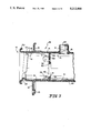
- FIG. 2 is a sectional view of a fuel filler tube containing a nozzle restrictor assembly in accordance with the present invention showing the displacement of a portion of the closure plate to an open position (dotted lines) in response to insertion of a fuel filler nozzle and to a closed position (solid lines) in response to withdrawal of the fuel filler nozzle;
- FIG. 3 is an enlarged sectional view of the fuel filler tube of FIG. 1 showing a layer of coating applied to the nozzle plate and the fuel filler tube;
- FIG. 4 is a view of the fuel filler tube of FIG. 1 showing the insertion of the closure plate into a slot formed in the coated nozzle restrictor plate during assembly operations in accordance with the method of the present invention
- FIG. 5 is a view similar to FIG. 3 showing the insertion of a locking tab on the closure plate into a second slot formed in the coated nozzle restrictor plate in accordance with the method of the present invention
- FIG. 6 is a further enlarged view of the restrictor assembly of FIG. 2 showing pivoting movement of a locking portion of the closure plate relative to the fixed restrictor plate to place a locking tab on the closure plate into a locking position engaging the coated nozzle restrictor plate;
- FIG. 7 is a view similar to FIG. 5 yet further enlarged showing the closure plate locked to the coated nozzle restrictor plate with the locking tab bearing against the restrictor plate and the closure portion moved to cover the nozzle-receiving opening formed in the restrictor plate;
- FIG. 8 is a top view of the restrictor assembly installed in a fuel filler tube shown in FIG. 2 as it would appear to a user who has removed the fuel cap from the fuel filler tube.
- a nozzle restrictor assembly 10 for use in accordance with the method of the present invention is illustrated in FIG. 1.
- a nozzle restrictor assembly 10 includes a restrictor plate 12 providing a nozzle opening 30 for receiving a properly sized fuel-dispensing nozzle therein and a closure plate 14 serving to normally cover opening 30.
- Restrictor assembly 10 is configured for mounting in a fuel filler tube 16 and functions to prevent a user from inserting one of the larger diameter nozzles used to dispense leaded fuels into the fuel filler tube 16.
- Fuel filler tube 16 shown in fragment in FIG. 1, includes a cylinder 15 having an inner end 17 attached to a vehicle fuel tank 13 and an outer end 18 configured to receive a fuel cap (not shown).
- Outer end 18 includes a curled-back rim 20 (shown in FIG. 2) which provides a seat for the fuel cap.
- Fuel filler tube 16 is also provided with a mounting plate 19 formed to include openings 21 for receiving rivets or other fasteners for mounting fuel filler tube 16 to a vehicle.
- Fuel filler tube 16 also includes a tube 23 for Venting fuel vapor as vehicle fuel tank 13 fills with gasoline. Referring to FIG. 2, tube 23 includes a crimped end 25 for attachment to fuel filler tube 16 at a location inside the region in the cylinder 15 between the fuel tank 13 and the nozzle restrictor assembly 10. Cylinder 15 also includes an inner wall 29 to which nozzle restrictor assembly 10 is attached. A layer of protective coating 41 is applied to fuel filler tube 16 and restrictor plate 12 as will be described.
- threads 22 are formed directly in cylinder 15 near outlet end 18 after the nozzle restrictor assembly 10 has been mounted inside the fuel filler tube 16.
- a fuel cap (not shown) provided with appropriate threading can engage threads 22 and seal against rim 20 to substantially prevent the escape of liquid fuel and fuel vapors from fuel filler tube 16 to the atmosphere.
- Restrictor plate 12 includes a first side 24 facing toward outer end 18 and a second side 26 facing into the filler tube 16 toward fuel tank 13.
- Restrictor plate 12 also includes a plurality of upstanding ears 28 spaced about its periphery as shown best in FIG. 1. Although three such ears 28 are shown in the illustrated embodiment, alternative designs are contemplated within the scope of the present invention. Ears 28 provide surfaces for spot welding restrictor plate 12 to inner wall 29 during assembly of restrictor assembly 10 into fuel filler tube 16 as described below. When assembled, restrictor plate 12 occupies the axial position inside cylinder 15 represented by dotted circle 27 in FIG. 1.
- restrictor plate 12 is formed to include nozzle opening 30 for receiving a fuel filler nozzle 33 during refueling. Opening 30 is provided with a diameter selected to admit only unleaded fuel-dispensing nozzles such as nozzle 33 and to block admission of conventional larger diameter leaded fuel-dispensing nozzles (not shown). Opening 30 is normally covered or closed by closure plate 14 at times other than during refueling as shown in FIG. 6, as will be described below.
- Restrictor plate 12 also is formed to include a first slot 32 formed to lie adjacent to opening 30 and a second slot 34 formed to lie between first slot 32 and the perimeter edge 35 of the restrictor plate 12. Slots 32 and 34 are sized and positioned to receive portions of closure plate 14 as shown in FIGS. 4-6. As will be subsequently described in greater detail, one portion of closure plate 14 is inserted in slot 32 (as indicated by dotted arrow 43 in FIG. 1) and another portion of closure plate 14 is pivoted (as indicated by dotted arrow 31) to close nozzle opening 30.
- Closure plate 14 is preferably fashioned of resilient stainless steel or other spring material and includes a closure portion 36, a hinge or spring portion 50, and a locking portion 38. Closure plate 14 is advantageously sized for insertion through first slot 32 is so that closure portion 36 bears against the inner side 26 of restrictor plate 12 as shown, for example, in solid lines in FIG. 2. When mounted on restrictor plate 12, closure plate 14 serves as a means for closing nozzle opening 30 upon withdrawal of a fuel filler nozzle 33 (shown in dotted lines in FIG. 2), for example, at the completion of refueling.
- Closure portion 36 of closure plate 14 normally covers nozzle opening 30 as shown best in FIG. 2 and FIG. 7.
- Closure portion 36 has a curved distal end 37.
- Locking portion 38 includes a locking tab 40 having a bent distal end 46. Locking tab is advantageously sized for insertion through second slot 34. Locking portion 38 also includes a depending tab 48, an upstanding tab 52, and a support tab 66 extending generally perpendicular to depending tab 48.
- Locking tab 40 cooperates with upstanding tab 52 to grip a radially outer portion 54 of restrictor plate 12 as shown in FIG. 7. Outer portion 54 is located between second slot 34 and the perimeter edge 35 of plate 12.
- locking tab 40 provides means for coupling closure portion 36 to restrictor plate 12 so that closure portion 36 is deflectable relative to restrictor plate 12 to move away from nozzle opening 30 during refueling upon insertion of a fuel filler nozzle
- closure plate 14 bends to occupy a deflected position 35 (shown in dotted lines in FIG. 2) but is movable to close nozzle opening 30 upon withdrawal of fuel filler nozzle 33.
- Spring portion 50 shown best in FIGS. 5-7, allows displacement of closure portion 36 away from nozzle opening 30 upon insertion of a small diameter unleaded fuel filler nozzle 33 into nozzle opening 30.
- Spring portion 50 connects locking portion 38 and closure portion 36 and extends through slot 32 when closure plate 14 is coupled to restrictor plate 12 as shown best in FIGS. 6-7.
- FIGS. 3-6 A method for mounting restrictor assembly 10 in a fuel filler tube 16 in accordance with the present invention is illustrated in FIGS. 3-6.
- restrictor plate 12 is attached to inner surface 29 of cylinder 15.
- ears 28 at the outside edge 35 of restrictor plate 12 are spot welded to inner surface 29 of the fuel filler tube 16 so that the outer surface 24 of restrictor plate 12 lies approximately 1.5 inches (3.8 cm) from outer end 18.
- the joints where ears 28 attach to inner wall 29 are not exposed to the atmosphere when the fuel cap (not shown) is attached to the outer end 18, but rather lie well within fuel filler tube 16.
- threads 22 are crimp-formed in cylinder 15 at outer end 18 using a hydraulic thread-sizing machine to perform a three-segment threading technique.
- curled-back rim 20 is formed at end 18 using a press operation to provide a flat sealing surface for a fuel cap (not shown).
- tube 16 and the restrictor plate 12 mounted therein are dip-coated with a protective coating 41 as shown in FIG. 3 to inhibit development of rust on the tube 16 and nozzle restrictor plate 12.
- the thickness of the coating 41 in FIG. 3 is illustrative only. It will be appreciated by those of ordinary skill in the art that coating 41 is a very thin layer as is typically achieved through a standard dip-coating process. A variety of coatings may be used, including paint, zinc, or a lead/tin coating.
- tube 16 is dipped into the coating bath after restrictor plate 12 has been attached to fuel filler tube 16 so that the restrictor plate 12 and fuel filler tube 16 are coated in a single step.
- closure plate 14 can be inserted through first slot 32 after restrictor plate 12 has been mounted in fuel filler tube 16 and coated with coating 41.
- the insertion sequence is illustrated in FIGS. 4-7.
- the relatively long closure portion 36 is first inserted through first slot 32, proceeding from outer side 24 of plate 12 into fuel filler tube 16 in the direction indicated by arrow 42 from left to right in FIG. 4.
- This inward movement of closure plate 14 ultimately causes bent distal end 46 to move in the direction indicated by arrow 44 as shown in FIG. 4 and enter the second slot 34 as shown in FIG. 5.
- Closure plate 14 will begin to pivot relative to the fixed restrictor plate 12 in direction 49 as shown in FIG. 6, with depending tab 48 serving as a pivot point.
- Such pivoting movement in direction 49 is a result of applying a force represented by arrow 53 to the spring portion 38 of spring plate 14 while inner segment of restrictor plate 12 is "nested" in the space between tabs 48, 66.
- locking tab 40 moves to engage the radially outer segment of restrictor plate 12 as shown in FIG. 6.
- Locking tab 40 and bent distal end 46 are biased or cammed from their original position 56 (shown in dotted lines) to the position shown in solid as indicated by arrow 58.
- the biasing force results from the compression of spring portion 50 and locking tab 40 as they are rotated in respective slots 32 and 34.
- closure plate 14 When pivoting movement of closure plate 14 relative to restrictor plate 12 is complete, closure plate 14 is placed in its operating position as shown in FIG. 7. As shown, radially outer segment 54 of restrictor plate 12 is trapped between locking tab 40 and upstanding tab 52 of spring plate 14. Inner segment 60 of restrictor plate 12 is trapped between depending tab 48 and spring portion 50 of closure plate 14. Depending tab 48 bears directly against outer side 24 of plate 12. Spring portion 50 extends through first slot 32 and bears against the inner segment 60. A central portion 64 of closure plate 14 bears against a central segment 62 of restrictor plate 12.
- Spring portion 50 extends through first slot 32 at an angle. When fuel filler nozzle 33 is inserted through nozzle opening 30, the nozzle 33 pushes closure portion 36 away from opening 30. Spring portion 50 bends to provide a hinge action, allowing closure portion 36 to move away from opening 30, as shown, for example, in FIG. 2 in dotted lines.
- Locking tab 40 bears against inner side 26 of restrictor plate 12 as shown in FIG. 7.
- the combined effects of locking tab 40 bearing against inner side 26 and tabs 48 and 52 bearing against outer side 24 ensure that closure plate 14 will remain attached to restrictor plate 12 even when closure portion 36 is forced away from opening 30 as during refueling.
- restrictor assembly 10 is shown as it would appear to a user preparing to refuel a fuel tank.
- Closure plate 14 is shown in its position blocking opening 30.
Landscapes
- Engineering & Computer Science (AREA)
- Life Sciences & Earth Sciences (AREA)
- Sustainable Development (AREA)
- Sustainable Energy (AREA)
- Chemical & Material Sciences (AREA)
- Combustion & Propulsion (AREA)
- Transportation (AREA)
- Mechanical Engineering (AREA)
- Cooling, Air Intake And Gas Exhaust, And Fuel Tank Arrangements In Propulsion Units (AREA)
Abstract
Description
Claims (29)
Priority Applications (2)
| Application Number | Priority Date | Filing Date | Title |
|---|---|---|---|
| US07/754,531 US5212864A (en) | 1991-09-04 | 1991-09-04 | Nozzle restrictor assembly and method of installing same |
| US08/056,835 US5385179A (en) | 1991-09-04 | 1993-05-03 | Nozzle restrictor assembly |
Applications Claiming Priority (1)
| Application Number | Priority Date | Filing Date | Title |
|---|---|---|---|
| US07/754,531 US5212864A (en) | 1991-09-04 | 1991-09-04 | Nozzle restrictor assembly and method of installing same |
Related Child Applications (1)
| Application Number | Title | Priority Date | Filing Date |
|---|---|---|---|
| US08/056,835 Division US5385179A (en) | 1991-09-04 | 1993-05-03 | Nozzle restrictor assembly |
Publications (1)
| Publication Number | Publication Date |
|---|---|
| US5212864A true US5212864A (en) | 1993-05-25 |
Family
ID=25035205
Family Applications (2)
| Application Number | Title | Priority Date | Filing Date |
|---|---|---|---|
| US07/754,531 Expired - Lifetime US5212864A (en) | 1991-09-04 | 1991-09-04 | Nozzle restrictor assembly and method of installing same |
| US08/056,835 Expired - Lifetime US5385179A (en) | 1991-09-04 | 1993-05-03 | Nozzle restrictor assembly |
Family Applications After (1)
| Application Number | Title | Priority Date | Filing Date |
|---|---|---|---|
| US08/056,835 Expired - Lifetime US5385179A (en) | 1991-09-04 | 1993-05-03 | Nozzle restrictor assembly |
Country Status (1)
| Country | Link |
|---|---|
| US (2) | US5212864A (en) |
Cited By (11)
| Publication number | Priority date | Publication date | Assignee | Title |
|---|---|---|---|---|
| US5457838A (en) * | 1993-09-21 | 1995-10-17 | Systems, Inc. | Extendible dock leveler |
| US20050236068A1 (en) * | 2004-04-22 | 2005-10-27 | Dayco Products, Llc | Modified fuel inlet restrictor |
| US20060032552A1 (en) * | 2004-08-11 | 2006-02-16 | Poul Hedevang | Fuel-dispensing nozzle inhibitor |
| US20060032549A1 (en) * | 2004-08-11 | 2006-02-16 | Mcclung Chad A | Fuel-dispensing nozzle inhibitor |
| US20060096662A1 (en) * | 2004-09-30 | 2006-05-11 | King Timothy J | Fuel-dispensing nozzle inhibitor |
| US20070034287A1 (en) * | 2005-02-10 | 2007-02-15 | Stant Manufacturing Inc. | Fuel-dispensing nozzle inhibitor |
| US7293586B2 (en) | 2005-06-22 | 2007-11-13 | Stant Manufacturing Inc. | Fuel-dispensing nozzle inhibitor |
| US20090020182A1 (en) * | 2007-07-19 | 2009-01-22 | Stant Manufacturing Inc. | Fuel-dispensing nozzle inhibitor |
| US20100206914A1 (en) * | 2007-10-16 | 2010-08-19 | Spoutlock Ltd. | Normally-closed openable closure device |
| US9415679B2 (en) | 2013-03-22 | 2016-08-16 | Stant Usa Corp. | Fuel-dispensing nozzle inhibitor |
| US10000117B2 (en) | 2012-02-17 | 2018-06-19 | Stant Usa Corp. | Filler neck closure assembly |
Families Citing this family (13)
| Publication number | Priority date | Publication date | Assignee | Title |
|---|---|---|---|---|
| DE19639825B4 (en) * | 1995-10-06 | 2008-02-14 | Volkswagen Ag | Misfuelling lock |
| JP3244008B2 (en) * | 1996-10-18 | 2002-01-07 | 豊田合成株式会社 | Fuel tank |
| US6330893B1 (en) * | 1999-12-03 | 2001-12-18 | Shelby Enterprises, Inc. | Fuel tank filter neck and method of manufacturing same |
| US7059365B2 (en) * | 1999-12-03 | 2006-06-13 | Shelby Enterprises, Inc. | Fuel tank filler neck and method of manufacturing same |
| US6588459B2 (en) * | 1999-12-03 | 2003-07-08 | Shelby Enterprises, Inc. | Fuel tank filler neck and method of manufacturing same |
| ITFR20030006U1 (en) * | 2003-03-20 | 2003-06-18 | Danilo Gigliozzi | SAFETY DEVICE SUITABLE TO AVOID THE POSSIBILITY OF INTRODUCING ANY LIQUID OR DUSTY SUBSTANCE IN ANY TANK |
| US7048019B2 (en) * | 2003-09-30 | 2006-05-23 | Shelby Enterprises, Inc. | Fuel filler tube assembly and manufacturing method |
| US6886582B2 (en) * | 2003-10-06 | 2005-05-03 | Young Ill Choi | Spare fuel tank in a fuel tank of a vehicle |
| JP2005297797A (en) * | 2004-04-13 | 2005-10-27 | Horie Metal Co Ltd | Fuel filler pipe for automobiles |
| FR2887498B1 (en) * | 2005-06-28 | 2008-09-05 | I T W De France Soc Par Action | HEAD FOR FUEL FILLING TUBE OF A VEHICLE |
| FR2887497B1 (en) * | 2005-06-28 | 2008-09-05 | I T W De France Soc Par Action | HEAD FOR FUEL FILLING TUBE OF A VEHICLE |
| USD542818S1 (en) * | 2005-07-01 | 2007-05-15 | Harley-Davidson Motor Company Group, Inc. | Oil fill neck |
| KR100786535B1 (en) * | 2007-05-07 | 2007-12-17 | 정호순 | Filler tube assembly of automobile |
Citations (2)
| Publication number | Priority date | Publication date | Assignee | Title |
|---|---|---|---|---|
| US4248279A (en) * | 1979-05-03 | 1981-02-03 | Chrysler Corporation | Tamper resistant fuel filler restrictor assembly |
| US4733791A (en) * | 1986-09-08 | 1988-03-29 | Sinclair Karl F | Replacement fill pipe restrictor |
Family Cites Families (8)
| Publication number | Priority date | Publication date | Assignee | Title |
|---|---|---|---|---|
| US641028A (en) * | 1899-06-22 | 1900-01-09 | Edward F Meehan | Air-pipe for drain-traps. |
| US721853A (en) * | 1901-10-28 | 1903-03-03 | Valentine G Bauer | Self-acting air-inlet. |
| US1280047A (en) * | 1916-04-17 | 1918-09-24 | Robert E Kurtz | Breather-pipe. |
| IT1016282B (en) * | 1973-07-17 | 1977-05-30 | Daimler Benz Ag | IMPROVEMENT IN THE FUEL TANKS FOR MOTOR VEHICLES |
| US4185844A (en) * | 1978-04-24 | 1980-01-29 | Chrysler Corporation | Fuel tank filler tube assembly |
| US4560084A (en) * | 1981-09-02 | 1985-12-24 | Burr-Brown Corporation | Heater preform for sealing a closure |
| US4527601A (en) * | 1983-09-12 | 1985-07-09 | Chrysler Corporation | Fuel tank inlet restrictor |
| US4529097A (en) * | 1984-11-02 | 1985-07-16 | Russell Larson | Insert for fuel filler restrictor assemblies |
-
1991
- 1991-09-04 US US07/754,531 patent/US5212864A/en not_active Expired - Lifetime
-
1993
- 1993-05-03 US US08/056,835 patent/US5385179A/en not_active Expired - Lifetime
Patent Citations (2)
| Publication number | Priority date | Publication date | Assignee | Title |
|---|---|---|---|---|
| US4248279A (en) * | 1979-05-03 | 1981-02-03 | Chrysler Corporation | Tamper resistant fuel filler restrictor assembly |
| US4733791A (en) * | 1986-09-08 | 1988-03-29 | Sinclair Karl F | Replacement fill pipe restrictor |
Cited By (19)
| Publication number | Priority date | Publication date | Assignee | Title |
|---|---|---|---|---|
| US5457838A (en) * | 1993-09-21 | 1995-10-17 | Systems, Inc. | Extendible dock leveler |
| US20050236068A1 (en) * | 2004-04-22 | 2005-10-27 | Dayco Products, Llc | Modified fuel inlet restrictor |
| US7278453B2 (en) | 2004-04-22 | 2007-10-09 | Fluid Routing Solutions, Inc. | Modified fuel inlet restrictor |
| US7182111B2 (en) | 2004-08-11 | 2007-02-27 | Stant Manufacturing Inc. | Fuel-dispensing nozzle inhibitor |
| US20060032552A1 (en) * | 2004-08-11 | 2006-02-16 | Poul Hedevang | Fuel-dispensing nozzle inhibitor |
| US20060032549A1 (en) * | 2004-08-11 | 2006-02-16 | Mcclung Chad A | Fuel-dispensing nozzle inhibitor |
| US7077178B2 (en) | 2004-08-11 | 2006-07-18 | Stant Manufacturing Inc. | Fuel-dispensing nozzle inhibitor |
| US20060096662A1 (en) * | 2004-09-30 | 2006-05-11 | King Timothy J | Fuel-dispensing nozzle inhibitor |
| US7302977B2 (en) | 2004-09-30 | 2007-12-04 | Stant Manufacturing Inc. | Fuel-dispensing nozzle inhibitor |
| US20070034287A1 (en) * | 2005-02-10 | 2007-02-15 | Stant Manufacturing Inc. | Fuel-dispensing nozzle inhibitor |
| US7665493B2 (en) | 2005-02-10 | 2010-02-23 | Stant Manufacturing Inc. | Fuel-dispensing nozzle inhibitor |
| US7293586B2 (en) | 2005-06-22 | 2007-11-13 | Stant Manufacturing Inc. | Fuel-dispensing nozzle inhibitor |
| US20090020182A1 (en) * | 2007-07-19 | 2009-01-22 | Stant Manufacturing Inc. | Fuel-dispensing nozzle inhibitor |
| US7967041B2 (en) | 2007-07-19 | 2011-06-28 | Stant Usa Corp. | Fuel-dispensing nozzle inhibitor |
| USRE46009E1 (en) | 2007-07-19 | 2016-05-24 | Stant Usa Corp. | Fuel-dispensing nozzle inhibitor |
| US20100206914A1 (en) * | 2007-10-16 | 2010-08-19 | Spoutlock Ltd. | Normally-closed openable closure device |
| EP2257491A4 (en) * | 2007-10-16 | 2011-11-02 | Spoutlock Ltd | Normally-closed openable closure device |
| US10000117B2 (en) | 2012-02-17 | 2018-06-19 | Stant Usa Corp. | Filler neck closure assembly |
| US9415679B2 (en) | 2013-03-22 | 2016-08-16 | Stant Usa Corp. | Fuel-dispensing nozzle inhibitor |
Also Published As
| Publication number | Publication date |
|---|---|
| US5385179A (en) | 1995-01-31 |
Similar Documents
| Publication | Publication Date | Title |
|---|---|---|
| US5212864A (en) | Nozzle restrictor assembly and method of installing same | |
| US6789586B2 (en) | Breakaway capless refueling assembly | |
| US6755057B2 (en) | Dust cover lock system for vehicle filler neck | |
| US6942117B2 (en) | Closure door system for vehicle filler neck | |
| US6691750B1 (en) | Floating nozzle collar for capless filler neck | |
| EP1479554B1 (en) | Flapper type fill tube check valve | |
| US6945290B1 (en) | Check valve for use in filler tube vapor recirculation system and method of making same | |
| EP1456051B1 (en) | One-way valve assembly for a fuel tank | |
| US7549443B2 (en) | Fuel shut-off valve assembly with associated components and methods of making and assembling the same | |
| US7458391B2 (en) | Assembling a siphonable filler tube with a check valve on a fuel tank | |
| US20110079322A1 (en) | Fuel filler system | |
| US20010013367A1 (en) | Check valve and fuel tank with check valve attached thereto | |
| CA2250668C (en) | Capless refueling assembly | |
| JP5346007B2 (en) | Improvement of fuel shut-off valve assembly and manufacturing / assembling method thereof | |
| US11358466B2 (en) | Capless closure for fuel filler pipe | |
| KR20100093068A (en) | Fill nozzle positioning apparatus | |
| US7762291B2 (en) | Capless closure assembly and method for fuel tank filler | |
| US4621964A (en) | Valve mounting assembly for aerosol containers and the like | |
| US20090139606A1 (en) | Contoured door with seal | |
| WO2006111818A2 (en) | Capless closure assembly and method for fuel tank filler | |
| US20190351759A1 (en) | Fuel tank fill assembly | |
| JP2520438Y2 (en) | Oil filler seal device | |
| JP2001113965A (en) | Fuel tank filler structure |
Legal Events
| Date | Code | Title | Description |
|---|---|---|---|
| AS | Assignment |
Owner name: ARVIN INDUSTRIES, INC., A CORP. OF IN Free format text: ASSIGNMENT OF ASSIGNORS INTEREST.;ASSIGNORS:BATES, DALE;SMITH, DANIEL N.;LITTLE, RICHARD F.;REEL/FRAME:005846/0263;SIGNING DATES FROM 19910826 TO 19910827 |
|
| STCF | Information on status: patent grant |
Free format text: PATENTED CASE |
|
| FEPP | Fee payment procedure |
Free format text: PAT HOLDER CLAIMS SMALL ENTITY STATUS - SMALL BUSINESS (ORIGINAL EVENT CODE: SM02); ENTITY STATUS OF PATENT OWNER: LARGE ENTITY |
|
| REMI | Maintenance fee reminder mailed | ||
| FPAY | Fee payment |
Year of fee payment: 4 |
|
| SULP | Surcharge for late payment | ||
| AS | Assignment |
Owner name: NBD BANK, MICHIGAN Free format text: SECURITY INTEREST;ASSIGNOR:PILOT INDUSTRIES, INC.;REEL/FRAME:008512/0093 Effective date: 19970328 |
|
| FEPP | Fee payment procedure |
Free format text: PAT HLDR NO LONGER CLAIMS SMALL ENT STAT AS SMALL BUSINESS (ORIGINAL EVENT CODE: LSM2); ENTITY STATUS OF PATENT OWNER: LARGE ENTITY |
|
| FPAY | Fee payment |
Year of fee payment: 8 |
|
| AS | Assignment |
Owner name: CERBERUS PILOT ACQUISITION III, INC., NEW YORK Free format text: ASSIGNMENT OF ASSIGNORS INTEREST;ASSIGNOR:PILOT INDUSTRIES, INC.;REEL/FRAME:012621/0671 Effective date: 20020130 |
|
| AS | Assignment |
Owner name: PILOT INDUSTRIES, INC., MICHIGAN Free format text: CHANGE OF NAME;ASSIGNOR:CERBERUS PILOT ACQUISITION III, INC.;REEL/FRAME:012841/0772 Effective date: 20020213 |
|
| AS | Assignment |
Owner name: CERBERUS PILOT HOLDINGS, LLC, NEW YORK Free format text: SECURITY AGREEMENT;ASSIGNORS:PILOT INDUSTRIES, INC.;CERBERUS PILOT ACQUISITION, LLC;REEL/FRAME:013727/0582 Effective date: 20021231 |
|
| AS | Assignment |
Owner name: MARTINREA INDUSTRIES INC., MICHIGAN Free format text: CHANGE OF NAME;ASSIGNOR:PILOT INDUSTRIES, INC.;REEL/FRAME:013532/0085 Effective date: 20030207 |
|
| AS | Assignment |
Owner name: MARTINREA INDUSTRIES, INC., CANADA Free format text: PAYOFF, TERMINATION AND RELEASE;ASSIGNOR:CEBERUS PILOT HOLDINGS, LLC;REEL/FRAME:014446/0375 Effective date: 20030627 |
|
| FPAY | Fee payment |
Year of fee payment: 12 |