JP2005297797A - Fuel filler pipe for automobiles - Google Patents
Fuel filler pipe for automobiles Download PDFInfo
- Publication number
- JP2005297797A JP2005297797A JP2004117741A JP2004117741A JP2005297797A JP 2005297797 A JP2005297797 A JP 2005297797A JP 2004117741 A JP2004117741 A JP 2004117741A JP 2004117741 A JP2004117741 A JP 2004117741A JP 2005297797 A JP2005297797 A JP 2005297797A
- Authority
- JP
- Japan
- Prior art keywords
- filler pipe
- fuel filler
- aluminum
- tube
- main body
- Prior art date
- Legal status (The legal status is an assumption and is not a legal conclusion. Google has not performed a legal analysis and makes no representation as to the accuracy of the status listed.)
- Pending
Links
Images
Classifications
-
- F—MECHANICAL ENGINEERING; LIGHTING; HEATING; WEAPONS; BLASTING
- F16—ENGINEERING ELEMENTS AND UNITS; GENERAL MEASURES FOR PRODUCING AND MAINTAINING EFFECTIVE FUNCTIONING OF MACHINES OR INSTALLATIONS; THERMAL INSULATION IN GENERAL
- F16L—PIPES; JOINTS OR FITTINGS FOR PIPES; SUPPORTS FOR PIPES, CABLES OR PROTECTIVE TUBING; MEANS FOR THERMAL INSULATION IN GENERAL
- F16L58/00—Protection of pipes or pipe fittings against corrosion or incrustation
- F16L58/02—Protection of pipes or pipe fittings against corrosion or incrustation by means of internal or external coatings
- F16L58/04—Coatings characterised by the materials used
- F16L58/08—Coatings characterised by the materials used by metal
-
- B—PERFORMING OPERATIONS; TRANSPORTING
- B60—VEHICLES IN GENERAL
- B60K—ARRANGEMENT OR MOUNTING OF PROPULSION UNITS OR OF TRANSMISSIONS IN VEHICLES; ARRANGEMENT OR MOUNTING OF PLURAL DIVERSE PRIME-MOVERS IN VEHICLES; AUXILIARY DRIVES FOR VEHICLES; INSTRUMENTATION OR DASHBOARDS FOR VEHICLES; ARRANGEMENTS IN CONNECTION WITH COOLING, AIR INTAKE, GAS EXHAUST OR FUEL SUPPLY OF PROPULSION UNITS IN VEHICLES
- B60K15/00—Arrangement in connection with fuel supply of combustion engines or other fuel consuming energy converters, e.g. fuel cells; Mounting or construction of fuel tanks
- B60K15/03—Fuel tanks
- B60K15/04—Tank inlets
-
- B—PERFORMING OPERATIONS; TRANSPORTING
- B60—VEHICLES IN GENERAL
- B60K—ARRANGEMENT OR MOUNTING OF PROPULSION UNITS OR OF TRANSMISSIONS IN VEHICLES; ARRANGEMENT OR MOUNTING OF PLURAL DIVERSE PRIME-MOVERS IN VEHICLES; AUXILIARY DRIVES FOR VEHICLES; INSTRUMENTATION OR DASHBOARDS FOR VEHICLES; ARRANGEMENTS IN CONNECTION WITH COOLING, AIR INTAKE, GAS EXHAUST OR FUEL SUPPLY OF PROPULSION UNITS IN VEHICLES
- B60K15/00—Arrangement in connection with fuel supply of combustion engines or other fuel consuming energy converters, e.g. fuel cells; Mounting or construction of fuel tanks
- B60K15/03—Fuel tanks
- B60K15/035—Fuel tanks characterised by venting means
- B60K2015/03523—Arrangements of the venting tube
Landscapes
- Engineering & Computer Science (AREA)
- General Engineering & Computer Science (AREA)
- Mechanical Engineering (AREA)
- Cooling, Air Intake And Gas Exhaust, And Fuel Tank Arrangements In Propulsion Units (AREA)
- Laminated Bodies (AREA)
- Rigid Pipes And Flexible Pipes (AREA)
Abstract
【課題】 アルミニウム製クラッドチューブを用いることにより軽量化を図ると共に防錆性能に優れた自動車用フューエルフィラパイプを提供すること。
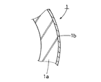
【解決手段】 車両に搭載される燃料タンク及びキャニスタと、車体に設けられる燃料給油口との間に介装される自動車用フューエルフィラパイプであって、フューエルフィラパイプfを構成するフィラパイプ本体部1と、フィラパイプ本体部1の拡径部分2に一端部5aを連通状に設けた循環チューブ5及び大気開放用チューブ6とを、アルミニウム合金の芯材1aと当該芯材に対して犠牲陽極作用を有するアルミニウム合金の外皮1bの二層構造からなるアルミニウム製クラッドチューブにより設けた。
【選択図】 図1PROBLEM TO BE SOLVED: To provide a fuel filler pipe for an automobile which is lightened by using an aluminum clad tube and has excellent rust prevention performance.
A fuel filler pipe for an automobile that is interposed between a fuel tank and a canister mounted on a vehicle and a fuel filler opening provided on a vehicle body, and a filler pipe main body portion constituting the fuel filler pipe f. 1 and a circulation tube 5 and an air release tube 6 in which one end portion 5a is provided in communication with the enlarged-diameter portion 2 of the filler pipe main body portion 1, and a sacrificial anode for the core material 1a of the aluminum alloy and the core material An aluminum clad tube having a two-layer structure of an outer skin 1b of an aluminum alloy having a function is provided.
[Selection] Figure 1
Description
本発明は、アルミニウム製クラッドチューブを用いた自動車用フューエルフィラパイプに関するものである。 The present invention relates to a fuel filler pipe for automobiles using an aluminum clad tube.
従来、自動車用フューエルフィラパイプは、金属製と合成樹脂製のものが使用されており、金属製フューエルフィラパイプについては、ステンレス製、アルミニウム製及び鉄製のものが使用されている。ステンレス製フューエルフィラパイプは幅広く使用されており、塗装等の防錆処理を施したものや、防錆処理を施さないものがある。また、アルミニウム製フューエルフィラパイプについては、自動車部品の軽量化に寄与することから一部の市販車種に採用されているが、単一構造(無垢)のアルミニウム材料を用いて防錆処理を施していないものである。 Conventionally, the fuel filler pipes for automobiles are made of metal and synthetic resin, and the metal fuel filler pipes are made of stainless steel, aluminum and iron. Stainless steel fuel filler pipes are widely used, and some have been subjected to rust prevention treatment such as painting and others are not subject to rust prevention treatment. In addition, aluminum fuel filler pipes are used in some commercial models because they contribute to reducing the weight of automobile parts, but they are rust-proofed using a single structure (solid) aluminum material. There is nothing.
合成樹脂製フューエルフィラパイプについては、軽量化を図るのに好都合であることから種々の提案がなされている。例えば、特開平8−91063号公報の「フューエルフィラパイプ」には、高密度ポリエチレンを主材としてブロー成形法により成形されたパイプ本体の外側面に、ガソリン等の燃料の透過を抑制するためのメッキ層を設けることにより、ガス透過防止機能を高める技術が開示されている。 Various proposals have been made for synthetic resin fuel filler pipes because they are convenient for reducing the weight. For example, in “Fuel Filler Pipe” of JP-A-8-91063, the outer surface of a pipe body formed by high-density polyethylene as a main material by a blow molding method is used to suppress the permeation of fuel such as gasoline. A technique for enhancing a gas permeation preventing function by providing a plating layer is disclosed.
金属製フューエルフィラパイプは、合成樹脂製のものに比べてガスバリヤ性に優れているが、重量が重くなり、また錆も発生し易い。そこで、軽量化や防錆性能に優れたフィラパイプの出現が要望されていた。
本発明の目的は、アルミニウム製クラッドチューブを用いることにより軽量化を図ると共に防錆性能に優れた自動車用フューエルフィラパイプを提供することにある。 An object of the present invention is to provide a fuel filler pipe for automobiles that is light in weight and excellent in rust prevention performance by using an aluminum clad tube.
前記目的を達成するために請求項1に記載した発明は、車両に搭載される燃料タンク及びキャニスタと、車体に設けられる燃料給油口との間に介装される自動車用フューエルフィラパイプであって、前記フューエルフィラパイプを構成するフィラパイプ本体部と、フィラパイプ本体部の上端部に一端部を連通状に設けられた循環チューブ及び大気開放用チューブとが、アルミニウム合金の芯材と当該芯材に対して犠牲陽極作用を有するアルミニウム合金の外皮の二層構造からなるアルミニウム製クラッドチューブにより夫々設けられていることを特徴とする。
In order to achieve the above object, the invention described in
同様の目的を達成するために請求項2に記載した発明は、車両に搭載される燃料タンクと、車体に設けられる燃料給油口との間に介装される自動車用フューエルフィラパイプであって、前記フューエルフィラパイプを構成するフィラパイプ本体部と、少なくともフィラパイプ本体部の上端部に一端部を連通状に設けられたブリーザチューブとが、アルミニウム合金の芯材と当該芯材に対して犠牲陽極作用を有するアルミニウム合金の外皮の二層構造からなるアルミニウム製クラッドチューブにより夫々設けられていることを特徴とする。 In order to achieve the same object, the invention described in claim 2 is a fuel filler pipe for an automobile that is interposed between a fuel tank mounted on a vehicle and a fuel filler opening provided on a vehicle body, A filler pipe main body constituting the fuel filler pipe, and a breather tube having one end connected to at least the upper end of the filler pipe main body, are a sacrificial anode for the aluminum alloy core and the core It is characterized by being provided by aluminum clad tubes each having a two-layer structure of an outer skin of an aluminum alloy having a function.
同様の目的を達成するために請求項3に記載した発明は、請求項1又は2に記載の自動車用フューエルフィラパイプにおいて、前記アルミニウム製クラッドチューブの芯材の化学成分が、Mn:0.6%〜1.5%(質量%、以下同じ)、Cu:0.05%〜0.5%、Si:0.6%以下(0%を含まず、以下同じ)、Fe:0.7%以下を含有し、残部アルミニウム及び不可避的不純物からなり、前記外皮の成分が、Zn:0.6%〜1.5%、Si+Fe≦0.7%を含有し、残部アルミニウム及び不可避的不純物からなり、さらに外皮のクラッド率が5〜15%であることを特徴とするものである。
In order to achieve the same object, the invention described in
同様の目的を達成するために請求項4に記載した発明は、請求項1から3の何れかに記載の自動車用フューエルフィラパイプにおいて、前記フィラパイプ本体部に固定される取付片がアルミニウム材料により設けられていることを特徴とするものである。
In order to achieve the same object, the invention described in claim 4 is the fuel filler pipe for automobiles according to any one of
(請求項1及び請求項2の発明)
この自動車用フューエルフィラパイプは、アルミニウム製クラッドチューブを採用することにより、従来の鉄製又はステンレス製のフューエルフィラパイプに比べて軽量化を図ることができると共に特にステンレス製のフューエルフィラパイプよりも低コストにて製造可能である。加えて、クラッドチューブの外皮のクラッド層によって芯材の孔食の発生が抑制されるために優れた防錆性能を有する。
(Invention of
This fuel filler pipe for automobiles can be made lighter than conventional steel or stainless steel fuel filler pipes by adopting an aluminum clad tube, and at a lower cost than stainless steel fuel filler pipes. Can be manufactured. In addition, since the occurrence of pitting corrosion of the core material is suppressed by the cladding layer of the cladding of the cladding tube, it has excellent rust prevention performance.
(請求項3の発明)
この自動車用フューエルフィラパイプは、クラッド率(「クラッドチューブの全体厚さに対する外皮のクラッド層の厚さの割合」をいう)を5〜15%とすることにより、顕著な防錆性能を有する。
(Invention of Claim 3)
This automotive fuel filler pipe has a remarkable rust prevention performance by setting the cladding rate (referring to the ratio of the thickness of the cladding layer of the outer shell to the total thickness of the cladding tube) of 5 to 15%.
(請求項4の発明)
この自動車用フューエルフィラパイプは、車体に固定するための取付片をアルミニウム材料としているので、フィラパイプ本体部と取付片との電食を防止することができる。
(Invention of Claim 4)
Since this fuel filler pipe for automobiles uses an aluminum material as an attachment piece for fixing to the vehicle body, it is possible to prevent electrolytic corrosion between the filler pipe body and the attachment piece.
以下に、本発明の最良の形態例を図面に基づいて説明する。図1から図5は第1実施形態例、図6及び図7は第2実施形態例にかかり、図1は自動車用フューエルフィラパイプの側面図、図2は同、平面図、図3は図1のA−A線図、図4は図2のB−B線図、図5はフィラパイプ本体部の一部を模式的に示す断面図、図6は自動車用フューエルフィラパイプの側面図、図7は同、平面図である。 The best mode of the present invention will be described below with reference to the drawings. 1 to 5 are related to the first embodiment, FIGS. 6 and 7 are related to the second embodiment, FIG. 1 is a side view of a fuel filler pipe for an automobile, FIG. 2 is the same plan view, and FIG. 4 is a BB diagram of FIG. 2, FIG. 5 is a sectional view schematically showing a part of the filler pipe main body, and FIG. 6 is a side view of a fuel filler pipe for an automobile. FIG. 7 is a plan view of the same.
(第1実施形態例)
本発明の第1実施形態例の自動車用フューエルフィラパイプ(以下、「フィラパイプ」という)fは、車両に搭載される燃料タンクと車体に設けられる燃料給油口との間に介装されるものである。
(First embodiment)
An automotive fuel filler pipe (hereinafter referred to as “filler pipe”) f of a first embodiment of the present invention is interposed between a fuel tank mounted on a vehicle and a fuel filler opening provided on the vehicle body. It is.
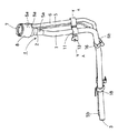
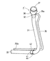
図1に示すように、フィラパイプfのフィラパイプ本体部1は、燃料給油口側の上端部の拡径部分2を除いてほぼ一様な大きさの円筒形状に形成されている。その拡径部分2の内方には、図示しないキャップを着脱可能とするリテーナ7が取り付けられている。そのリテーナ7と拡径部分2の外周囲には、合成樹脂製筒型カバー8が緊密に取り付けられている。このフィラパイプ本体部1は、図5に示すアルミニウム合金の芯材1aと当該芯材に対して犠牲陽極作用を有するアルミニウム合金の外皮(クラッド層)1bの二層構造からなる耐食性に優れたクラッドチューブを用いて所定形状に加工されている。
As shown in FIG. 1, the filler pipe
因みに、この実施形態例のフィラパイプ本体部1に用いるアルミニウム製クラッドチューブは、以下に示す化学成分からなるものであり、外径35〜25.4mm、全体の厚さ1〜1.2mm、外皮1bの厚さ約100μmとしたものである。
Incidentally, the aluminum clad tube used for the filler pipe
アルミニウム製クラッドチューブの芯材1aの化学成分については、Mn:0.6%〜1.5%(質量%、以下同じ)、Cu:0.05%〜0.5%、Si:0.6%以下(0%を含まず、以下同じ)、Fe:0.7%以下を含有し、残部アルミニウム及び不可避的不純物からなり、前記外皮1bの成分については、Zn:0.6%〜1.5%、Si+Fe≦0.7%を含有し、残部アルミニウム及び不可避的不純物からなるものである。
Regarding the chemical composition of the
また、外皮1bのクラッド率については、5〜15%の範囲の数値であることが好ましく、より好ましくは6〜12%である。このクラッド率については、5%未満では耐食性が不十分であり、15%を超えると製造が困難となる。
The cladding ratio of the
上記アルミニウム製クラッドチューブの化学成分を限定した理由について説明する。
(イ)芯材の化学成分
Mnは、芯材の強度の向上と耐食性を高めるものである。Mnの含有量は、0.6%〜1.5%(質量%、以下同じ)であり、0.6%未満では強度が不足し、1.5%を超えると加工性が低下する。なお、より好ましくは、1.0%〜1.2%である。
The reason why the chemical components of the aluminum clad tube are limited will be described.
(A) Chemical component of core material Mn increases the strength and corrosion resistance of the core material. The content of Mn is 0.6% to 1.5% (mass%, the same applies hereinafter). If it is less than 0.6%, the strength is insufficient, and if it exceeds 1.5%, the workability is lowered. In addition, More preferably, it is 1.0%-1.2%.
Cuは、芯材の強度の向上と耐食性を高める。Cuの含有量は、0.05%〜0.5%であり、0.05%未満では強度が不足し、0.5%を超えると加工性が低下する。なお、より好ましくは、0.05%〜0.2%である。 Cu improves the strength and corrosion resistance of the core material. The Cu content is 0.05% to 0.5%. If it is less than 0.05%, the strength is insufficient, and if it exceeds 0.5%, the workability is lowered. More preferably, it is 0.05% to 0.2%.
Siは、アルミニウム合金に不純物として含まれるものである。Siの含有量は、0.6%以下(0%を含まず、以下同じ)であり、0.6%を超えると加工性が低下する。なお、より好ましくは、0.2%以下である。 Si is contained as an impurity in the aluminum alloy. The Si content is 0.6% or less (excluding 0%, the same shall apply hereinafter), and if it exceeds 0.6%, the workability deteriorates. In addition, More preferably, it is 0.2% or less.
Feは、アルミニウム合金に不純物として含まれるものであり、耐食性を低下させるため、含有量は0.7%以下とするのが好ましい。なお、より好ましくは、0.2%〜0.6%である。 Fe is contained as an impurity in the aluminum alloy, and its content is preferably 0.7% or less in order to reduce the corrosion resistance. In addition, More preferably, it is 0.2%-0.6%.
(ロ)外皮の化学成分
Znは、芯材に対する犠牲陽極効果を発揮し芯材の孔食の発生を防止する。Znの含有量は、0.6%〜1.5%であり、0.6%未満では芯材との間の電位差不足により耐食性が低下し、1.5%を超えると外皮の自己腐食速度が増大し耐食性が低下する。なお、より好ましくは、0.8%〜1.2%である。
(B) Chemical component of outer shell Zn exhibits a sacrificial anode effect on the core material and prevents the occurrence of pitting corrosion of the core material. The Zn content is 0.6% to 1.5%, and if it is less than 0.6%, the corrosion resistance is lowered due to insufficient potential difference with the core material, and if it exceeds 1.5%, the self-corrosion rate of the outer skin. Increases and corrosion resistance decreases. In addition, More preferably, it is 0.8%-1.2%.
Si、Feは、アルミニウム合金に不純物として含まれるものであるが、何れも耐食性を低下させるので、それらを合計して0.7%以下であることが好ましい。なお、より好ましくは、0.2%〜0.5%である。 Si and Fe are contained as impurities in the aluminum alloy, but both lower the corrosion resistance. Therefore, the total content of Si and Fe is preferably 0.7% or less. More preferably, it is 0.2% to 0.5%.
5は前記フィラパイプ本体部1の拡径部分2に一端部5aを連通状に接続し、他端部5bをフィラパイプ本体部1の出口3の近くまで延びるように設けられた循環チューブである。この循環チューブ5は、フィラパイプ本体部1と同様に、アルミニウム合金の芯材とアルミニウム合金の外皮の二層構造からなるクラッドチューブを用いて所定形状に加工されている。この実施形態例の循環チューブ5に用いたアルミニウム製クラッドチューブは、外径14〜6.35mm、全体の厚さを0.8〜1.2mm、外皮の厚さを約100μmとしたものである。
6は上記カバー8の側部に一体に形成された気化ガス開放口8aに一端部6aを挿入し、公知のキャニスター側に接続される他端部6bをフィラパイプ本体部1のほぼ中間位置まで延びるように設けられた大気開放用チューブである。この大気開放用チューブ6は、フィラパイプ本体部1と同様に、アルミニウム合金の芯材とアルミニウム合金の外皮の二層構造からなるクラッドチューブを用いて所定形状に加工されている。この実施形態例の大気開放用チューブ6に用いたアルミニウム製クラッドチューブは、外径12〜20mm、全体の厚さを0.8〜1.2mm、外皮の厚さを約100μmとしたものである。
6, one
上記ブリーザチューブ5及び大気開放用チューブ6については、フィラパイプfを車体に取り付けるためのアルミニウム製取付片11とアルミニウム製保持片16とにより、フィラパイプ本体部1に対して固定されている。
The
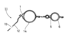
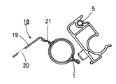
その取付片11は、図3に示すように、取付穴13が形成された本体部12と押さえ片14とにより、フィラパイプ本体部1と循環チューブ5及び大気開放用チューブ6を挟持して固定するように設けられている。18はフィラパイプ本体部1の出口3の近くに固定されたアルミニウム製取付片である。この取付片18は、図4に示すように、取付穴20が形成された本体部19と押さえ片21とによりフィラパイプ本体部1を挟持して固定されている。
As shown in FIG. 3, the mounting
以上により、第1実施形態例のフィラパイプfが構成される。 The filler pipe f of the first embodiment is configured as described above.
(第2実施形態例)
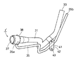
本発明の第2実施形態例のフィラパイプf′は、フィラパイプ本体部31とブリーザチューブ35とから構成されており、第1実施形態例のフィラパイプfと比べると、大気開放用チューブをフィラパイプ本体部31に一体状に設けていない点が相違する。
因みに、このタイプのフィラパイプf′を使用する燃料供給システムでは、大気開放用チューブを燃料タンクとキャニスタとの間に配設する構成とされている。
(Second Embodiment)
The filler pipe f ′ according to the second embodiment of the present invention includes a filler pipe
Incidentally, in the fuel supply system using this type of filler pipe f ′, an atmosphere release tube is arranged between the fuel tank and the canister.
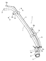
図6に示すように、フィラパイプf′のフィラパイプ本体部31は、燃料給油口側の上端部の拡径部分32を除いてほぼ一様な大きさの円筒形状に形成されている。その拡径部分32の内方には、図示しないキャップを着脱可能とするリテーナ37が取り付けられている。そのリテーナ37と拡径部分32の外周囲には、合成樹脂製筒型カバー38が緊密に取り付けられている。このフィラパイプ本体部31は、前記第1実施形態例のフィラパイプ本体部1と同一素材の耐食性に優れたアルミニウム製クラッドチューブを用いて所定形状に加工されている。
As shown in FIG. 6, the filler pipe
35は前記フィラパイプ本体部31の拡径部分32に一端部35aを連通状に接続し、他端部35bをフィラパイプ本体部31の出口33の近くまで延びるように設けられたブリーザチューブである。このブリーザチューブ35は、前記第1実施形態例の循環チューブ5と同一素材のアルミニウム製クラッドチューブを用いて所定形状に加工されている。
上記ブリーザチューブ35については、フィラパイプf′を車体に取り付けるためのアルミニウム製取付片41によりフィラパイプ本体部31に対して固定されている。その取付片41は、取付穴43が形成された本体部42と押さえ片44とにより、フィラパイプ本体部31とブリーザチューブ35を挟持して固定するように設けられている。
The
以上により、第2実施形態例のフィラパイプf′が構成される。 Thus, the filler pipe f ′ of the second embodiment is configured.
本発明の自動車用フューエルフィラパイプに用いるアルミニウム製クラッドチューブの実施例を比較例と対比して説明する。 An example of an aluminum clad tube used for a fuel filler pipe for an automobile of the present invention will be described in comparison with a comparative example.
(実施例)
表1に示す芯材用合金の周囲に表2に示す外皮用合金を配した二層構造のビレットを用いて常法の製造方法により、表3に示すクラッドチューブ(外径:25mm、全体の厚さ1mm)を得た。
(Example)
The clad tube (outer diameter: 25 mm, overall diameter) shown in Table 3 was prepared by a conventional manufacturing method using a billet having a two-layer structure in which the outer alloy shown in Table 2 was arranged around the core alloy shown in Table 1. A thickness of 1 mm) was obtained.

上記クラッドチューブを用いて上記フィラパイプfのフィラパイプ本体部の形状に加工された試験片(表3、記号1〜14)を作製し、それらの試験片について、腐食試験(耐食性)と加工性の実験を行った。
(1)腐食試験
上記試験片について、JASO M 610-92(自動車部品外観腐食試験方法)に基づきサイクル試験(180サイクル)を実施し、貫通腐食の有無を調べた。
Test pieces (Table 3,
(1) Corrosion test The above test piece was subjected to a cycle test (180 cycles) based on JASO M 610-92 (automobile part appearance corrosion test method) to examine the presence or absence of penetration corrosion.
(2)加工性
上記試験片について、拡径加工による割れの有無を調べた。
(2) Workability About the said test piece, the presence or absence of the crack by diameter expansion processing was investigated.
実験の結果、表3に示すように、記号1〜14の試験片は、貫通腐食がなく耐食性に優れ、拡径加工による割れが発生しなく加工性が良好であった。
As a result of the experiment, as shown in Table 3, the test pieces of
(比較例)
表1の記号A及び表4に示す芯材用合金のビレットと、表2の記号a及び表5に示す外皮用合金のビレットとを用いて上記実施例と同様の製造方法により、表6に示すクラッドチューブ(外径:25mm、全体の厚さ1mm)を得た。そして、そのクラッドチューブを用いて上記実施例と同様の試験片(表6、記号15〜23)を作製し、それらの試験片について、実施例と同様に、腐食試験と加工性の実験を行った。
(Comparative example)
Using the billet of the core alloy shown in Table 1 and Table 4 and the bill a of Table 2 and the outer alloy billet shown in Table 5, the same manufacturing method as in the above example, Table 6 The resulting cladding tube (outer diameter: 25 mm,
実験の結果、表6に示すように、記号15〜23の試験片は、何れも耐食性及び加工性の両方を満足するものがなく、自動車用フューエルフィラパイプに用いるアルミニウム製クラッドチューブとして適応しないものであることが確認された。 As a result of the experiment, as shown in Table 6, none of the test pieces of symbols 15 to 23 satisfy both corrosion resistance and workability, and are not applicable as aluminum clad tubes used for automobile fuel filler pipes. It was confirmed that.
以上に述べた通り、この自動車用フューエルフィラパイプは、アルミニウム製クラッドチューブを採用することにより、従来の鉄製又はステンレス製のフューエルフィラパイプに比べて約50パーセントの軽量化を図ることができると共にステンレス製のものよりも製造コストを削減することができる。加えて、クラッドチューブのクラッド層によって優れた防錆性能を得られる利点がある。 As described above, the fuel filler pipe for an automobile can be reduced in weight by about 50% compared to the conventional steel or stainless steel fuel filler pipe by using an aluminum clad tube and is made of stainless steel. Manufacturing costs can be reduced as compared with those manufactured. In addition, there is an advantage that excellent rust prevention performance can be obtained by the clad layer of the clad tube.
f・・・自動車用フューエルフィラパイプ
1・・・フィラパイプ本体部
1a・・・芯材
1b・・・外皮(クラッド層)
5・・・循環チューブ
6・・・大気開放用チューブ
11,18・・・取付片
f′・・・自動車用フューエルフィラパイプ
31・・・フィラパイプ本体部
35・・・ブリーザチューブ
41・・・取付片
f ... Fuel filler pipe for
5 ...
Claims (4)
前記フューエルフィラパイプを構成するフィラパイプ本体部と、フィラパイプ本体部の上端部に一端部を連通状に設けられた循環チューブ及び大気開放用チューブとが、アルミニウム合金の芯材と当該芯材に対して犠牲陽極作用を有するアルミニウム合金の外皮の二層構造からなるアルミニウム製クラッドチューブにより夫々設けられていることを特徴とする自動車用フューエルフィラパイプ。 A fuel filler pipe for automobiles interposed between a fuel tank and a canister mounted on a vehicle and a fuel filler opening provided in a vehicle body,
A filler pipe main body constituting the fuel filler pipe, and a circulation tube and an air release tube having one end connected to the upper end of the filler pipe main body are formed of an aluminum alloy core material and the core material. A fuel filler pipe for an automobile, which is provided with an aluminum clad tube having a two-layer structure of an aluminum alloy skin having a sacrificial anodic action.
前記フューエルフィラパイプを構成するフィラパイプ本体部と、少なくともフィラパイプ本体部の上端部に一端部を連通状に設けられたブリーザチューブとが、アルミニウム合金の芯材と当該芯材に対して犠牲陽極作用を有するアルミニウム合金の外皮の二層構造からなるアルミニウム製クラッドチューブにより夫々設けられていることを特徴とする自動車用フューエルフィラパイプ。 A fuel filler pipe for automobiles interposed between a fuel tank mounted on a vehicle and a fuel filler opening provided on a vehicle body,
A filler pipe main body constituting the fuel filler pipe, and a breather tube having at least one end connected to the upper end of the filler pipe main body in a continuous manner are an aluminum alloy core material and a sacrificial anode for the core material. A fuel filler pipe for an automobile, which is provided by an aluminum clad tube having a two-layer structure of an outer skin of an aluminum alloy having a function.
The fuel filler pipe for an automobile according to any one of claims 1 to 3, wherein the attachment piece fixed to the filler pipe main body is made of an aluminum material.
Priority Applications (2)
| Application Number | Priority Date | Filing Date | Title |
|---|---|---|---|
| JP2004117741A JP2005297797A (en) | 2004-04-13 | 2004-04-13 | Fuel filler pipe for automobiles |
| US11/104,973 US7021343B2 (en) | 2004-04-13 | 2005-04-13 | Fuel filler pipe for automobile |
Applications Claiming Priority (1)
| Application Number | Priority Date | Filing Date | Title |
|---|---|---|---|
| JP2004117741A JP2005297797A (en) | 2004-04-13 | 2004-04-13 | Fuel filler pipe for automobiles |
Publications (1)
| Publication Number | Publication Date |
|---|---|
| JP2005297797A true JP2005297797A (en) | 2005-10-27 |
Family
ID=35059338
Family Applications (1)
| Application Number | Title | Priority Date | Filing Date |
|---|---|---|---|
| JP2004117741A Pending JP2005297797A (en) | 2004-04-13 | 2004-04-13 | Fuel filler pipe for automobiles |
Country Status (2)
| Country | Link |
|---|---|
| US (1) | US7021343B2 (en) |
| JP (1) | JP2005297797A (en) |
Cited By (2)
| Publication number | Priority date | Publication date | Assignee | Title |
|---|---|---|---|---|
| JP2008273513A (en) * | 2007-05-07 | 2008-11-13 | Ho Soon Jung | Filler tube assembly of automobile |
| JP2016013827A (en) * | 2014-06-09 | 2016-01-28 | 豊田合成株式会社 | Fuel supply device |
Families Citing this family (8)
| Publication number | Priority date | Publication date | Assignee | Title |
|---|---|---|---|---|
| EP1852297B1 (en) | 2006-05-01 | 2009-01-07 | Ford Global Technologies, LLC | Fuel filler assembly for a motor vehicle |
| US20080271814A1 (en) * | 2007-05-04 | 2008-11-06 | Gm Global Technology Operations, Inc. | Honeycomb Flame Arrester and Flow Straightener for a Fuel System Fuel Fill Pipe |
| US20110114636A1 (en) * | 2009-11-16 | 2011-05-19 | Glenn Erckert | Two-sided automobile fuel filling system |
| EP2923875B1 (en) * | 2014-03-25 | 2016-05-18 | Magna Steyr Fuel Systems GesmbH | Filling device and method for producing a filling device |
| US9776501B2 (en) * | 2015-02-18 | 2017-10-03 | Toyota Motor Engineering & Manufacturing North America, Inc. | Protection of vehicle fluid conduits |
| DOP2015000109A (en) * | 2015-05-13 | 2015-06-30 | Adriam Eduardo Mendez Gomez | DOUBLE INPUT SYSTEM FOR FUEL TANK SUPPLY FOR MOTOR VEHICLE |
| US20250170888A1 (en) * | 2022-03-29 | 2025-05-29 | TopFlo, LLC | Floating suction line |
| US12083878B2 (en) * | 2022-03-29 | 2024-09-10 | Fuel Tank Optics, Llc | Fuel tank floating suction line with level indicator |
Citations (6)
| Publication number | Priority date | Publication date | Assignee | Title |
|---|---|---|---|---|
| JPH01145487A (en) * | 1987-12-01 | 1989-06-07 | Furukawa Alum Co Ltd | Piping made of aluminum |
| JPH08158972A (en) * | 1994-12-12 | 1996-06-18 | Nissan Motor Co Ltd | Fuel tank device |
| JP2000026931A (en) * | 1998-05-01 | 2000-01-25 | Mitsubishi Alum Co Ltd | Aluminum alloy brazing sheet for formation of brazed tube, and brazed tube |
| JP2000203278A (en) * | 1999-01-11 | 2000-07-25 | Futaba Industrial Co Ltd | Fuel inlet |
| JP2003127676A (en) * | 2001-10-23 | 2003-05-08 | Horie Metal Co Ltd | Earth structure of fuel inlet pipe |
| JP2003252071A (en) * | 2002-03-05 | 2003-09-09 | Toyota Motor Corp | Fuel supply device |
Family Cites Families (3)
| Publication number | Priority date | Publication date | Assignee | Title |
|---|---|---|---|---|
| IT1016282B (en) * | 1973-07-17 | 1977-05-30 | Daimler Benz Ag | IMPROVEMENT IN THE FUEL TANKS FOR MOTOR VEHICLES |
| US5212864A (en) * | 1991-09-04 | 1993-05-25 | Arvin Industries, Inc. | Nozzle restrictor assembly and method of installing same |
| JP2001353519A (en) * | 2000-06-14 | 2001-12-25 | Suncall Corp | Dual structured clad tube and its manufacturing method |
-
2004
- 2004-04-13 JP JP2004117741A patent/JP2005297797A/en active Pending
-
2005
- 2005-04-13 US US11/104,973 patent/US7021343B2/en not_active Expired - Lifetime
Patent Citations (6)
| Publication number | Priority date | Publication date | Assignee | Title |
|---|---|---|---|---|
| JPH01145487A (en) * | 1987-12-01 | 1989-06-07 | Furukawa Alum Co Ltd | Piping made of aluminum |
| JPH08158972A (en) * | 1994-12-12 | 1996-06-18 | Nissan Motor Co Ltd | Fuel tank device |
| JP2000026931A (en) * | 1998-05-01 | 2000-01-25 | Mitsubishi Alum Co Ltd | Aluminum alloy brazing sheet for formation of brazed tube, and brazed tube |
| JP2000203278A (en) * | 1999-01-11 | 2000-07-25 | Futaba Industrial Co Ltd | Fuel inlet |
| JP2003127676A (en) * | 2001-10-23 | 2003-05-08 | Horie Metal Co Ltd | Earth structure of fuel inlet pipe |
| JP2003252071A (en) * | 2002-03-05 | 2003-09-09 | Toyota Motor Corp | Fuel supply device |
Cited By (2)
| Publication number | Priority date | Publication date | Assignee | Title |
|---|---|---|---|---|
| JP2008273513A (en) * | 2007-05-07 | 2008-11-13 | Ho Soon Jung | Filler tube assembly of automobile |
| JP2016013827A (en) * | 2014-06-09 | 2016-01-28 | 豊田合成株式会社 | Fuel supply device |
Also Published As
| Publication number | Publication date |
|---|---|
| US7021343B2 (en) | 2006-04-04 |
| US20050224135A1 (en) | 2005-10-13 |
Similar Documents
| Publication | Publication Date | Title |
|---|---|---|
| EP2746422B1 (en) | Aluminum plated steel sheet having excellent corrosion resistance with respect to alcohol or mixed gasoline of same and appearance and method of production of same | |
| CN102015423B (en) | Use of a metal composite material in a vehicle structure | |
| JP2005297797A (en) | Fuel filler pipe for automobiles | |
| JP4940229B2 (en) | Manufacturing method of liner component | |
| JP3497413B2 (en) | Surface treated steel sheet for fuel containers with excellent corrosion resistance, workability and weldability | |
| KR101231949B1 (en) | Stainless steel flux-cored welding wire for the welding of galvanized steel sheets and process for arc welding of galvanized steel sheets with the same | |
| DE102009055608A1 (en) | Brazed aluminum heat exchanger | |
| JP6412596B2 (en) | Inexpensive automotive parts and oil pipes with excellent salt corrosion resistance | |
| JP2005247295A (en) | Stainless frame structure for motor vehicle | |
| Franke et al. | Progress in ductile aluminium high pressure die casting alloys for the automotive industry | |
| JP5916314B2 (en) | Extruded pipe members such as aluminum alloy tanks for heat exchangers | |
| KR20190076129A (en) | Hot dip aluminium alloy plated steel sheet having excellent corrosion resistance and weldability, method for manufacturing the same | |
| DE102011112589A1 (en) | Wheel hub for a motor vehicle | |
| US7935427B2 (en) | Magnesium alloy part and production method thereof | |
| CN106011559A (en) | Bush inner core of automobile engine | |
| KR20220113811A (en) | Method of manufacturing a component for storing or dispensing compressed gas and a component for storing or dispensing compressed gas | |
| DE102017003234A1 (en) | Body part for a passenger car, method for coating such a body part and method for producing a coating for such a body part | |
| JP2007154927A (en) | High-pressure tank | |
| JP6541992B2 (en) | Automotive parts and automotive fueling pipes excellent in puncture resistance utilizing painting and sacrificial corrosion protection effect | |
| JPH11152555A (en) | Corrosion-resistant steel plates for fuel tanks with excellent corrosion resistance and weldability | |
| US11203807B2 (en) | Coating for a carrier material, core part for producing a composite part, composite part, and method for producing a composite part | |
| KR101243006B1 (en) | Aluminium plated ferritic stainless steel welding method | |
| CN106004417B (en) | A kind of oil filling pipe and its processing method with double side zinc coating structure | |
| CN107949719A (en) | Elastic parts and wires for elastic parts | |
| DE102005055321A1 (en) | Container for storing fuel |
Legal Events
| Date | Code | Title | Description |
|---|---|---|---|
| A621 | Written request for application examination |
Free format text: JAPANESE INTERMEDIATE CODE: A621 Effective date: 20070223 |
|
| A977 | Report on retrieval |
Free format text: JAPANESE INTERMEDIATE CODE: A971007 Effective date: 20090930 |
|
| A131 | Notification of reasons for refusal |
Free format text: JAPANESE INTERMEDIATE CODE: A131 Effective date: 20091006 |
|
| A521 | Written amendment |
Free format text: JAPANESE INTERMEDIATE CODE: A523 Effective date: 20091126 |
|
| A02 | Decision of refusal |
Free format text: JAPANESE INTERMEDIATE CODE: A02 Effective date: 20100520 |