US5205169A - Angle of attack sensor using inverted ratio of pressure differentials - Google Patents
Angle of attack sensor using inverted ratio of pressure differentials Download PDFInfo
- Publication number
- US5205169A US5205169A US07/741,955 US74195591A US5205169A US 5205169 A US5205169 A US 5205169A US 74195591 A US74195591 A US 74195591A US 5205169 A US5205169 A US 5205169A
- Authority
- US
- United States
- Prior art keywords
- attack
- signal
- angle
- pressure
- measured
- Prior art date
- Legal status (The legal status is an assumption and is not a legal conclusion. Google has not performed a legal analysis and makes no representation as to the accuracy of the status listed.)
- Expired - Lifetime
Links
Images


Classifications
-
- G—PHYSICS
- G01—MEASURING; TESTING
- G01P—MEASURING LINEAR OR ANGULAR SPEED, ACCELERATION, DECELERATION, OR SHOCK; INDICATING PRESENCE, ABSENCE, OR DIRECTION, OF MOVEMENT
- G01P13/00—Indicating or recording presence, absence, or direction, of movement
- G01P13/02—Indicating direction only, e.g. by weather vane
- G01P13/025—Indicating direction only, e.g. by weather vane indicating air data, i.e. flight variables of an aircraft, e.g. angle of attack, side slip, shear, yaw
Definitions
- the present invention relates to an apparatus and a method for extending the useful range of direct angle of attack measurements with non-movable sensors.
- the present invention provides an apparatus and method utilizing differential pressure measurements from properly located angle sensing ports on a probe for determining angle of attack on a probe. For a wide range of angles from a reference position or zero angle, the calculation is a ratio of the measured differential pressure (P 1 -P 2 ), divided by measured impact pressure (q cm ). As angles of attack increase substantially from zero reference, the quantity q cm , measured impact pressure, becomes approximately zero.
- the present invention comprises inverting the quantity or ratio used for calculation when the normal denominator is still a reliable number. The differential pressure quantity then becomes the denominator or divisor and the measured impact pressure becomes the numerator of the ratio.
- the inversion of the ratio can be implemented by utilization of a comparator that will switch between the first and second ratios when the quantity or value of the measured impact pressure reaches a desired value.
- One switch value is when the ratio reaches a value of 1.0.
- the measured impact pressure approaches zero in the range of 65°. Selecting the switchover point for inversion of the ratio, with measured impact pressure becoming a numerator and differential pressure the denominator, at a whole number value of the measured impact pressure, ensures that the output angle of attack signal will remain reliable across a greater range.
- the extension of the range of reliable angle of attack measurements using pneumatic signals is increasingly important, and has been one of the sought after goals since the development of probes such as that shown in U.S. Pat. No. 3,318,146 back in the 1960's.
- the present invention provides simple, reliable means of obtaining the necessary readings without complex hardware or software.
- FIG. 1 is a plan view of a strut mounted air data sensing probe which has sensing ports useful for determining angle of attack in accordance with the present invention
- FIG. 2 is a front view of the probe of FIG. 1;
- FIG. 3 is a fragmentary enlarged front view of the probe of FIG. 1;
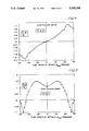
- FIG. 4 is a graph containing a plot of pressure differential between two ports facing in opposite directions and having axes in the plane in which angle of attack is measured;
- FIG. 5 is a graph containing a plot of measured impact pressure variations within the range in sensor angle of attack
- FIG. 6 is a graph containing a plot of an angle of attack signal for a probe of the type shown in FIG. 1 with the inversion function of the present invention.
- FIG. 7 is a block diagram of instrumentation used with the probe of FIG. 1 for carrying out the present invention.
- FIG. 1 is an illustrative example of the type of probe that can be used with the present invention.
- the probe 10 includes a strut or support section 13 and a cylindrical section 14 supported by the strut.
- the cylindrical section 14 is a tube that has a tapered end 15, although the forward end could be a hemispherical head as shown in the sensor or probe of U.S. Pat. No. 3,318,146.
- the tube 14 has a central axis that is preferably aligned with, or at a known relationship to, the axis longitudinal reference of the air vehicle.
- a forwardly facing port 16 is centered on the central axis, and is at the leading end.
- Third and fourth ports 22 and 23 are sometimes provided in the end portion 15 and have their axes lying on a plane passing through the longitudinal axis of the tube section 14 and perpendicular to the plane of the axes of ports 20 and 21.
- the axes of ports 22 and 23 lie in a plane indicated at 25 generally perpendicular to the mounting surface 12.
- Each of the ports, including port 16, is connected to a separate pressure carrying conduit so the pressures can be individually plumbed to desired sensors.
- Such conduits are shown generally at 30, 31 and 33 in FIG. 1.
- P 1 port 20
- P 2 port 21
- P m is a measured static pressure.
- P m can be an average of pressure sensed at ports 20 and 21 or the average of pressure sensed at ports 22 and 23, or can be a separate static pressure measured on the sensor.
- P t'm is the measured pitot pressure, measured at port 16.
- the ratio (P 1 -P 2 )/q c shows a large sensitivity to angles of attack to about ⁇ 70°, and then levels out (becomes less sensitive) and starts to decrease as the angle of attack approaches 90°.
- the denominator pressure differential (P 3 -P 4 ) of the prior art equation also varies with angle of attack.
- FIG. 5 a plot is made wherein the differential pressure (P 3 -P 4 ) or (P t'm -P m ) is labeled q cm , or measured impact pressure. It is obtained essentially by subtracting the measured static pressure P m from the measured pitot pressure P t'm .
- the inverted ratio q cm /(P 1 -P 2 ) continues to provide a useable range of angle of attack signal from the change over point to about ⁇ 80° angle of attack.
- the normal ratio is used in region A, indicated at 37.
- the graph plot 38 reverses direction as at 38A and 38B, for the two regions B shown at 39A and 39B, even though the angle of attack continues to increase in the same direction (positive angles at region 38B and negative angles at region 38A).
- the curve can again reverse at extremely high value angles, for example 80° and above.
- the Mach number does affect the curve form at high angles of attack in particular, but this can be compensated in a provided air data computer.
- the sensor or probe design used is symmetrical in the plane of angle of attack.
- the quantity (P 1 -P 2 ) is negative at negative angles of attack, but has the same absolute magnitudes as at positive angles of attack, except the sign of the pressure differential is reversed.
- the sign of the pressure differential (P 1 -P 2 ) can be used to determine whether the angle of attack is positive or negative when used in control functions of an air vehicle.
- the instrumentation shown in FIG. 7 is used for carrying out the inversion function.
- the angle of attack sensor is indicated in this drawing at 30, and has pressure lines 31, 32, 33, 34 and 35 carrying the individual pressure signals.
- Pressure sensors indicated schematically at 38 are provided for either averaging back pressures to one sensor or subtracting (differential sensor) the pressures as needed for the ratio quantities.
- the signal from the pitot pressure port, P t'm , and the P m signals are fed along lines 40 and 42, respectively, to a subtractor 44 that provides an output along the line 45 representing q cm . This is a measured quantity.
- a signal generator 47 provides an electrical signal along the line 48 that is equal to the signal that is the selected switching value of the q cm signal along line 45. Lines carrying these signals are connected to the inputs of a comparator 49.
- an air data computer 52 provides a calculation of (P 1 -P 2 )/q cm as an output.
- the (P 1 -P 2 ) signal is fed along a line 54 to the air data computer 52, and the q cm signal is provided along a line 56 to the air data computer 52.
- the "select" signal (comparator output) on line 58 which may normally be low, goes to high when the signal from the q cm calculation circuit passes the threshold value as it moves toward zero.
- the change in signal on line 58 causes the computer to provide an output selected in accordance with the ratio q cm /(P 1 -P 2 ).
- the ratios for the two calculations from the air data computer in this particular application are indicated in boxes 62 and 64, respectively. It is well known to provide a division output from air data computers. Also, a Mach number factor 66 can be provided for compensation in a well known manner. The Mach number compensation is used on existing systems.
- the output indication of angle of attack on line 60 is a digital or analog signal that would be provided in accordance with the plot of the output shown in FIG. 6, and by switching the ratio when the value of (P 1 -P 2 )/q cm equals either ⁇ 1, respectively, as q cm is moving toward zero, reliable results are obtained.
- the region from approximately -48° angle of attack to +48° angle of attack is utilizing the equation or ratio shown at 62 in the air data computer, and the equation or ratio shown at 64 is used between -48° angle of attack and -90° as well as from +48° angle of attack to +90° angle of attack.
- the threshold or switching value can represent an angle of attack of between about 35° and 55° depending on the sensor designs, and reliable signals will still be received. Thus, the threshold value used for providing the select signal could be properly scaled and compared to the actual angle of attack output on line 60 for the inversion command.
- the (P 1 -P 2 )/q cm quantity is slightly sensitive to Mach number so the signal representing the ratios are normally compensated at higher angles of attack with a factor representing Mach number.
- the compensation factor can be obtained by wind tunnel tests and provided as compensation in the air data computer.
- Usable angle of attack signals are therefore provided across a wider range of angles of attack, than previously done.
Landscapes
- Engineering & Computer Science (AREA)
- Aviation & Aerospace Engineering (AREA)
- Physics & Mathematics (AREA)
- General Physics & Mathematics (AREA)
- Measuring Fluid Pressure (AREA)
- Indicating Or Recording The Presence, Absence, Or Direction Of Movement (AREA)
Abstract
Description
Claims (10)
Priority Applications (4)
| Application Number | Priority Date | Filing Date | Title |
|---|---|---|---|
| US07/741,955 US5205169A (en) | 1991-08-08 | 1991-08-08 | Angle of attack sensor using inverted ratio of pressure differentials |
| DE69222172T DE69222172T2 (en) | 1991-08-08 | 1992-07-14 | SETTING ANGLE SENSOR BASED ON THE REVERSE RATIO OF PRESSURE DIFFERENCES |
| EP92915820A EP0597899B1 (en) | 1991-08-08 | 1992-07-14 | Angle of attack sensor using inverted ratio of pressure differentials |
| PCT/US1992/005875 WO1993003326A1 (en) | 1991-08-08 | 1992-07-14 | Angle of attack sensor using inverted ratio of pressure differentials |
Applications Claiming Priority (1)
| Application Number | Priority Date | Filing Date | Title |
|---|---|---|---|
| US07/741,955 US5205169A (en) | 1991-08-08 | 1991-08-08 | Angle of attack sensor using inverted ratio of pressure differentials |
Publications (1)
| Publication Number | Publication Date |
|---|---|
| US5205169A true US5205169A (en) | 1993-04-27 |
Family
ID=24982921
Family Applications (1)
| Application Number | Title | Priority Date | Filing Date |
|---|---|---|---|
| US07/741,955 Expired - Lifetime US5205169A (en) | 1991-08-08 | 1991-08-08 | Angle of attack sensor using inverted ratio of pressure differentials |
Country Status (4)
| Country | Link |
|---|---|
| US (1) | US5205169A (en) |
| EP (1) | EP0597899B1 (en) |
| DE (1) | DE69222172T2 (en) |
| WO (1) | WO1993003326A1 (en) |
Cited By (33)
| Publication number | Priority date | Publication date | Assignee | Title |
|---|---|---|---|---|
| WO2000049419A1 (en) * | 1999-02-22 | 2000-08-24 | Rosemount Aerospace Inc. | Method to measure high angles of attack and mach number of a sensor probe |
| US6271769B1 (en) * | 1997-12-02 | 2001-08-07 | Proprietary Software Systems, Inc. | Apparatus and method for measuring and displaying angular deviations from angle of zero lift for air vehicles |
| US6543298B2 (en) | 2001-07-13 | 2003-04-08 | Rosemount Aerospace Inc. | Method of reducing total temperature errors and multi-function probe implementing same |
| US6561020B2 (en) | 2001-05-08 | 2003-05-13 | Rosemount Aerospace Inc. | Method to calculate sideslip angle and correct static pressure for sideslip effects using inertial information |
| US6594559B2 (en) | 2001-05-08 | 2003-07-15 | Rosemount Aerospace Inc. | Iterative method of aircraft sideslip compensation for multi-function probe air data systems |
| US6604029B2 (en) | 2001-05-08 | 2003-08-05 | Rosemount Aerospace Inc. | Multi-function air data probes using neural network for sideslip compensation |
| US6609421B2 (en) | 2001-05-08 | 2003-08-26 | Rosemount Aerospace Inc. | Sideslip correction for a multi-function three probe air data system |
| US6668640B1 (en) | 2002-08-12 | 2003-12-30 | Rosemount Aerospace Inc. | Dual-channel electronic multi-function probes and methods for realizing dissimilar and independent air data outputs |
| US20040122615A1 (en) * | 2002-12-23 | 2004-06-24 | Cronin Dennis J. | Multi-function air data probes employing neural networks for determining local air data parameters |
| US6761057B2 (en) * | 2001-09-13 | 2004-07-13 | Rosemount Aerospace Inc. | Error detection and fault isolation for multi-function air data probes and systems |
| US6940425B2 (en) * | 1997-12-02 | 2005-09-06 | James B. Frantz | Apparatus and method for determining information for aircraft |
| GB2424285A (en) * | 2005-03-16 | 2006-09-20 | Rosemount Aerospace Inc | Method and Apparatus for Extending Useful Range of Air Data Parameter Calculation In Flush Air Data Systems |
| US20060225496A1 (en) * | 2005-04-06 | 2006-10-12 | Rosemount Aerospace Inc. | Method and apparatus for obtaining improved accuracy and range for air data parameters inferred from independent measurements of interdependent pressures |
| US20070130096A1 (en) * | 2005-12-01 | 2007-06-07 | Rosemount Aerospace, Inc. | Fault detection in artificial intelligence based air data systems |
| US20070150122A1 (en) * | 2004-10-29 | 2007-06-28 | Rosemount Aerospace Inc. | Fault isolation method and apparatus in artificial intelligence based air data systems |
| US20070251313A1 (en) * | 2005-08-16 | 2007-11-01 | Thomas Steven H | Methods and system for determining angles of attack and sideslip using flow sensors |
| US20090311096A1 (en) * | 2008-06-13 | 2009-12-17 | Stefan Herr | Method and apparatus for measuring air flow condition at a wind turbine blade |
| US20100258678A1 (en) * | 2009-04-09 | 2010-10-14 | Nicholas Jonathan Fermor | Aircraft stall protection system |
| US20110013664A1 (en) * | 2007-05-14 | 2011-01-20 | Rosemount Aerospace Inc. | Aspirated enhanced total air temperature probe |
| RU183334U1 (en) * | 2018-04-27 | 2018-09-18 | Акционерное общество "Аэроприбор - Восход" | Multifunctional Air Data Meter |
| US10670479B2 (en) | 2018-02-27 | 2020-06-02 | Methode Electronics, Inc. | Towing systems and methods using magnetic field sensing |
| US10696109B2 (en) | 2017-03-22 | 2020-06-30 | Methode Electronics Malta Ltd. | Magnetolastic based sensor assembly |
| US11014417B2 (en) | 2018-02-27 | 2021-05-25 | Methode Electronics, Inc. | Towing systems and methods using magnetic field sensing |
| US11084342B2 (en) | 2018-02-27 | 2021-08-10 | Methode Electronics, Inc. | Towing systems and methods using magnetic field sensing |
| US11135882B2 (en) | 2018-02-27 | 2021-10-05 | Methode Electronics, Inc. | Towing systems and methods using magnetic field sensing |
| US11184201B2 (en) | 2019-05-15 | 2021-11-23 | Astrapi Corporation | Communication devices, systems, software and methods employing symbol waveform hopping |
| US11221262B2 (en) | 2018-02-27 | 2022-01-11 | Methode Electronics, Inc. | Towing systems and methods using magnetic field sensing |
| US11228477B2 (en) | 2019-03-06 | 2022-01-18 | Astrapi Corporation | Devices, systems, and methods employing polynomial symbol waveforms |
| US11240088B2 (en) | 2011-04-15 | 2022-02-01 | Astrapi Corporation | Methods and systems for transmitting and receiving data using non-periodic functions |
| US11310090B2 (en) | 2016-05-23 | 2022-04-19 | Astrapi Corporation | Systems, transmitters, and methods employing waveform bandwidth compression to transmit information |
| US11411785B2 (en) | 2015-09-02 | 2022-08-09 | Astrapi Corporation | Spiral polynomial division multiplexing |
| US11491832B2 (en) | 2018-02-27 | 2022-11-08 | Methode Electronics, Inc. | Towing systems and methods using magnetic field sensing |
| US11824694B2 (en) | 2015-09-02 | 2023-11-21 | Astrapi Corporation | Systems, devices, and methods employing instantaneous spectral analysis in the transmission of signals |
Families Citing this family (2)
| Publication number | Priority date | Publication date | Assignee | Title |
|---|---|---|---|---|
| FR2791773B1 (en) * | 1999-04-02 | 2001-06-15 | Sextant Avionique | VANE FOR DIRECTION IN THE AXIS OF AN AMBIENT AIR FLOW |
| FR2983965B1 (en) * | 2011-12-12 | 2014-07-04 | Thales Sa | LOCAL IMPACT MEASUREMENT PROBE AND METHOD USING THE SENSOR |
Citations (5)
| Publication number | Priority date | Publication date | Assignee | Title |
|---|---|---|---|---|
| US3318146A (en) * | 1966-02-14 | 1967-05-09 | Rosemount Eng Co Ltd | Pressure sensing instrument for aircraft |
| US4096744A (en) * | 1975-09-05 | 1978-06-27 | Rosemount Inc. | Pressure sensor for determining airspeed, altitude and angle of attack |
| US4378696A (en) * | 1981-02-23 | 1983-04-05 | Rosemount Inc. | Pressure sensor for determining airspeed altitude and angle of attack |
| US4836019A (en) * | 1987-08-27 | 1989-06-06 | Rosemount Inc. | Compact air data sensor |
| US5025661A (en) * | 1989-12-11 | 1991-06-25 | Allied-Signal Inc. | Combination air data probe |
Family Cites Families (1)
| Publication number | Priority date | Publication date | Assignee | Title |
|---|---|---|---|---|
| US4388691A (en) * | 1981-01-23 | 1983-06-14 | The Babcock & Wilcox Company | Velocity pressure averaging system |
-
1991
- 1991-08-08 US US07/741,955 patent/US5205169A/en not_active Expired - Lifetime
-
1992
- 1992-07-14 EP EP92915820A patent/EP0597899B1/en not_active Expired - Lifetime
- 1992-07-14 DE DE69222172T patent/DE69222172T2/en not_active Expired - Lifetime
- 1992-07-14 WO PCT/US1992/005875 patent/WO1993003326A1/en active IP Right Grant
Patent Citations (5)
| Publication number | Priority date | Publication date | Assignee | Title |
|---|---|---|---|---|
| US3318146A (en) * | 1966-02-14 | 1967-05-09 | Rosemount Eng Co Ltd | Pressure sensing instrument for aircraft |
| US4096744A (en) * | 1975-09-05 | 1978-06-27 | Rosemount Inc. | Pressure sensor for determining airspeed, altitude and angle of attack |
| US4378696A (en) * | 1981-02-23 | 1983-04-05 | Rosemount Inc. | Pressure sensor for determining airspeed altitude and angle of attack |
| US4836019A (en) * | 1987-08-27 | 1989-06-06 | Rosemount Inc. | Compact air data sensor |
| US5025661A (en) * | 1989-12-11 | 1991-06-25 | Allied-Signal Inc. | Combination air data probe |
Cited By (47)
| Publication number | Priority date | Publication date | Assignee | Title |
|---|---|---|---|---|
| US6271769B1 (en) * | 1997-12-02 | 2001-08-07 | Proprietary Software Systems, Inc. | Apparatus and method for measuring and displaying angular deviations from angle of zero lift for air vehicles |
| US6940425B2 (en) * | 1997-12-02 | 2005-09-06 | James B. Frantz | Apparatus and method for determining information for aircraft |
| EP1637891A1 (en) * | 1999-02-22 | 2006-03-22 | Rosemount Aerospace Inc. | Method to measure high angles of attack and mach number of a sensor probe |
| US6305218B1 (en) | 1999-02-22 | 2001-10-23 | Rosemount Aerospace Inc. | Method of and apparatus for using an alternate pressure to measure mach number at high probe angles of attack |
| WO2000049419A1 (en) * | 1999-02-22 | 2000-08-24 | Rosemount Aerospace Inc. | Method to measure high angles of attack and mach number of a sensor probe |
| US6561020B2 (en) | 2001-05-08 | 2003-05-13 | Rosemount Aerospace Inc. | Method to calculate sideslip angle and correct static pressure for sideslip effects using inertial information |
| US6594559B2 (en) | 2001-05-08 | 2003-07-15 | Rosemount Aerospace Inc. | Iterative method of aircraft sideslip compensation for multi-function probe air data systems |
| US6604029B2 (en) | 2001-05-08 | 2003-08-05 | Rosemount Aerospace Inc. | Multi-function air data probes using neural network for sideslip compensation |
| US6609421B2 (en) | 2001-05-08 | 2003-08-26 | Rosemount Aerospace Inc. | Sideslip correction for a multi-function three probe air data system |
| US6543298B2 (en) | 2001-07-13 | 2003-04-08 | Rosemount Aerospace Inc. | Method of reducing total temperature errors and multi-function probe implementing same |
| US6761057B2 (en) * | 2001-09-13 | 2004-07-13 | Rosemount Aerospace Inc. | Error detection and fault isolation for multi-function air data probes and systems |
| US6668640B1 (en) | 2002-08-12 | 2003-12-30 | Rosemount Aerospace Inc. | Dual-channel electronic multi-function probes and methods for realizing dissimilar and independent air data outputs |
| US7379839B2 (en) | 2002-12-23 | 2008-05-27 | Rosemount Aerospace, Inc. | Multi-function air data probes employing neural networks for determining local air data parameters |
| US20060155506A1 (en) * | 2002-12-23 | 2006-07-13 | Rosemount Aerospace Inc. | Multi-function air data probes employing neural networks for determining local air data parameters |
| US20040122615A1 (en) * | 2002-12-23 | 2004-06-24 | Cronin Dennis J. | Multi-function air data probes employing neural networks for determining local air data parameters |
| US20070150122A1 (en) * | 2004-10-29 | 2007-06-28 | Rosemount Aerospace Inc. | Fault isolation method and apparatus in artificial intelligence based air data systems |
| US7257470B2 (en) | 2004-10-29 | 2007-08-14 | Rosemount Aerospace Inc. | Fault isolation method and apparatus in artificial intelligence based air data systems |
| GB2424285B (en) * | 2005-03-16 | 2009-04-29 | Rosemount Aerospace Inc | Method and apparatus for extending useful range of air data parameter calculation in flush air data systems |
| GB2424285A (en) * | 2005-03-16 | 2006-09-20 | Rosemount Aerospace Inc | Method and Apparatus for Extending Useful Range of Air Data Parameter Calculation In Flush Air Data Systems |
| US7213454B2 (en) | 2005-04-06 | 2007-05-08 | Rosemount Aerospace Inc. | Method and apparatus for obtaining improved accuracy and range for air data parameters inferred from independent measurements of interdependent pressures |
| US20060225496A1 (en) * | 2005-04-06 | 2006-10-12 | Rosemount Aerospace Inc. | Method and apparatus for obtaining improved accuracy and range for air data parameters inferred from independent measurements of interdependent pressures |
| US20070251313A1 (en) * | 2005-08-16 | 2007-11-01 | Thomas Steven H | Methods and system for determining angles of attack and sideslip using flow sensors |
| US7377159B2 (en) * | 2005-08-16 | 2008-05-27 | Honeywell International Inc. | Methods and system for determining angles of attack and sideslip using flow sensors |
| US20070130096A1 (en) * | 2005-12-01 | 2007-06-07 | Rosemount Aerospace, Inc. | Fault detection in artificial intelligence based air data systems |
| US20110013664A1 (en) * | 2007-05-14 | 2011-01-20 | Rosemount Aerospace Inc. | Aspirated enhanced total air temperature probe |
| US8104955B2 (en) | 2007-05-14 | 2012-01-31 | Rosemount Aerospace Inc. | Aspirated enhanced total air temperature probe |
| US20090311096A1 (en) * | 2008-06-13 | 2009-12-17 | Stefan Herr | Method and apparatus for measuring air flow condition at a wind turbine blade |
| US8408871B2 (en) | 2008-06-13 | 2013-04-02 | General Electric Company | Method and apparatus for measuring air flow condition at a wind turbine blade |
| US20100258678A1 (en) * | 2009-04-09 | 2010-10-14 | Nicholas Jonathan Fermor | Aircraft stall protection system |
| US11848812B2 (en) | 2011-04-15 | 2023-12-19 | Astrapi Corporation | Methods and systems for communicating |
| US11240088B2 (en) | 2011-04-15 | 2022-02-01 | Astrapi Corporation | Methods and systems for transmitting and receiving data using non-periodic functions |
| US11824694B2 (en) | 2015-09-02 | 2023-11-21 | Astrapi Corporation | Systems, devices, and methods employing instantaneous spectral analysis in the transmission of signals |
| US11411785B2 (en) | 2015-09-02 | 2022-08-09 | Astrapi Corporation | Spiral polynomial division multiplexing |
| US11310090B2 (en) | 2016-05-23 | 2022-04-19 | Astrapi Corporation | Systems, transmitters, and methods employing waveform bandwidth compression to transmit information |
| US10696109B2 (en) | 2017-03-22 | 2020-06-30 | Methode Electronics Malta Ltd. | Magnetolastic based sensor assembly |
| US10940726B2 (en) | 2017-03-22 | 2021-03-09 | Methode Electronics Malta Ltd. | Magnetoelastic based sensor assembly |
| US11221262B2 (en) | 2018-02-27 | 2022-01-11 | Methode Electronics, Inc. | Towing systems and methods using magnetic field sensing |
| US11135882B2 (en) | 2018-02-27 | 2021-10-05 | Methode Electronics, Inc. | Towing systems and methods using magnetic field sensing |
| US11084342B2 (en) | 2018-02-27 | 2021-08-10 | Methode Electronics, Inc. | Towing systems and methods using magnetic field sensing |
| US11014417B2 (en) | 2018-02-27 | 2021-05-25 | Methode Electronics, Inc. | Towing systems and methods using magnetic field sensing |
| US11491832B2 (en) | 2018-02-27 | 2022-11-08 | Methode Electronics, Inc. | Towing systems and methods using magnetic field sensing |
| US10670479B2 (en) | 2018-02-27 | 2020-06-02 | Methode Electronics, Inc. | Towing systems and methods using magnetic field sensing |
| RU183334U1 (en) * | 2018-04-27 | 2018-09-18 | Акционерное общество "Аэроприбор - Восход" | Multifunctional Air Data Meter |
| US11228477B2 (en) | 2019-03-06 | 2022-01-18 | Astrapi Corporation | Devices, systems, and methods employing polynomial symbol waveforms |
| US11729041B2 (en) | 2019-03-06 | 2023-08-15 | Astrapi Corporation | Devices, systems, and methods employing polynomial symbol waveforms |
| US11184201B2 (en) | 2019-05-15 | 2021-11-23 | Astrapi Corporation | Communication devices, systems, software and methods employing symbol waveform hopping |
| US11582075B2 (en) | 2019-05-15 | 2023-02-14 | Astrapi Corporation | Communication devices, systems, software and methods employing symbol waveform hopping |
Also Published As
| Publication number | Publication date |
|---|---|
| DE69222172D1 (en) | 1997-10-16 |
| EP0597899A1 (en) | 1994-05-25 |
| EP0597899A4 (en) | 1996-05-22 |
| EP0597899B1 (en) | 1997-09-10 |
| WO1993003326A1 (en) | 1993-02-18 |
| DE69222172T2 (en) | 1998-01-22 |
Similar Documents
| Publication | Publication Date | Title |
|---|---|---|
| US5205169A (en) | Angle of attack sensor using inverted ratio of pressure differentials | |
| US4096744A (en) | Pressure sensor for determining airspeed, altitude and angle of attack | |
| EP0167585B1 (en) | Pressure sensing instrument for aircraft | |
| US3318146A (en) | Pressure sensing instrument for aircraft | |
| US6305218B1 (en) | Method of and apparatus for using an alternate pressure to measure mach number at high probe angles of attack | |
| US4718273A (en) | Combination alpha, static and total pressure probe | |
| EP0073809B1 (en) | Pressure sensor for determining airspeed, altitude and angle of attack | |
| US4378697A (en) | Strut mounted multiple static tube | |
| US6679112B2 (en) | Total pressure determination with multifunction probe for aircraft | |
| US4696194A (en) | Fluid flow measurement | |
| US5406839A (en) | Incidence probe with multiple pressure inlets | |
| US7201067B2 (en) | System and method for determining flow characteristics | |
| WO2007022177A2 (en) | Methods and system for determining angles of attack and sideslip using flow sensors | |
| US6644112B2 (en) | Air data measuring device and air data system for flight vehicles | |
| JPH0566538B2 (en) | ||
| US4361054A (en) | Hot-wire anemometer gyro pickoff | |
| EP1020717B1 (en) | Pitot-static probe | |
| Sahin et al. | The measurement of air-flow characteristics using a five-hole Pitot probe in conjunction with a microcomputer | |
| SU1120244A1 (en) | Flow velocity transmitter | |
| JPS63223569A (en) | Method and device for calibrating anemometer for measuring air current | |
| RU2149370C1 (en) | Pressure pickup | |
| RU2073872C1 (en) | Device for measurement of horizontal wind velocity | |
| JPS63313007A (en) | Measuring instrument for axial elongation quantity of rotary body | |
| JPH08334527A (en) | Current meter |
Legal Events
| Date | Code | Title | Description |
|---|---|---|---|
| AS | Assignment |
Owner name: ROSEMOUNT INC., A CORPORATION OF MN, MINNESOTA Free format text: ASSIGNMENT OF ASSIGNORS INTEREST.;ASSIGNOR:HAGEN, FLOYD W.;REEL/FRAME:005807/0090 Effective date: 19910808 |
|
| STCF | Information on status: patent grant |
Free format text: PATENTED CASE |
|
| FPAY | Fee payment |
Year of fee payment: 4 |
|
| FPAY | Fee payment |
Year of fee payment: 8 |
|
| FPAY | Fee payment |
Year of fee payment: 12 |
|
| AS | Assignment |
Owner name: THE B.F.GOODRICH COMPANY, OHIO Free format text: ASSIGNMENT OF ASSIGNORS INTEREST;ASSIGNOR:ROSEMOUNT INC.;REEL/FRAME:023292/0656 Effective date: 19931211 |
|
| AS | Assignment |
Owner name: GOODRICH CORPORATION, NORTH CAROLINA Free format text: CHANGE OF NAME;ASSIGNOR:THE B.F.GOODRICH COMPANY;REEL/FRAME:023319/0460 Effective date: 20010601 |