US520199A - Track or carrier for doors - Google Patents
Track or carrier for doors Download PDFInfo
- Publication number
- US520199A US520199A US520199DA US520199A US 520199 A US520199 A US 520199A US 520199D A US520199D A US 520199DA US 520199 A US520199 A US 520199A
- Authority
- US
- United States
- Prior art keywords
- tube
- rollers
- doors
- hangers
- carrier
- Prior art date
- Legal status (The legal status is an assumption and is not a legal conclusion. Google has not performed a legal analysis and makes no representation as to the accuracy of the status listed.)
- Expired - Lifetime
Links
Images
Classifications
-
- E—FIXED CONSTRUCTIONS
- E05—LOCKS; KEYS; WINDOW OR DOOR FITTINGS; SAFES
- E05D—HINGES OR SUSPENSION DEVICES FOR DOORS, WINDOWS OR WINGS
- E05D15/00—Suspension arrangements for wings
- E05D15/06—Suspension arrangements for wings for wings sliding horizontally more or less in their own plane
- E05D15/0621—Details, e.g. suspension or supporting guides
- E05D15/0626—Details, e.g. suspension or supporting guides for wings suspended at the top
- E05D15/063—Details, e.g. suspension or supporting guides for wings suspended at the top on wheels with fixed axis
Definitions
- My invention relates to a device for suspending sliding or traveling doors or carriers, and for other similar purposes.
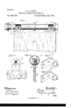
- Figure l is a front view of my invention, a portion being broken away showing the construction.
- Fig.2 is a cross section of the tube showing the pulley and hanger.
- Fig. 3 shows the hanger with a transverse section of the sleeve.
- Fig. 4 is a view of one of the end brackets.
- Fig. 5 is a view of the intermediate bracket.
- the object of my invention is to provide a device for suspending any traveler which is intended to run from one point to another. It is applicable to the suspension of car and other sliding doors, and also for transporting hay in barns, and for other similar purposes.
- A is the tube made of any suitable or desired diameter. It may be made of gas pipe of suitable size, and it has a slot or channel B made in the lower side.
- This tube is suitably supported by brackets O, the end ones being closed, and the tube may be secured in place by caps or nuts screwing upon these ends and outside of the end brackets, so that by removing a cap the tube may he slid back and the interior rollers removed.
- Intermediate brackets, through or beyond which the traveler is to pass, are slotted or channeled upon the lower side so as to allow the traveler hangers to pass them. These intermediate brackets extend far enough around the tubes so as to give it the proper support at a suitable number of points, without interfering with the free movement of the hangers. In case of a sliding door, two end brackets,
- D D are the hangers to which the door or other suspended part E is secured.
- These hangers are in the form of plates of sufficient thickness to give the required strength and at the same time to pass freely up through the slot B in the tube.
- rollers F which travel within the tube and thus suspend the hangers and the load which they carry.
- These rollers are made in the form of flattened spherical segments having a sulficient space between their inner faces to ad mit the hanger plates, and a central axle uniting them upon which the hanger plates rest.
- the outer faces of these segments are flattened so as not to form contact with the inner sides of the tube and the edges where they approach the sides of the slot B are also made flat so that they do not travel upon this slot.
- the curvature between this straight portion and the outer faces is essentially the same as the inner curvature of the tube, so that these rollers travel upon a curved surface which corresponds with the inner surface of the tube, and they thus run easily.
- rollers In order to provide a sufficient bearing for the hangers so that the weight will not cause them to wear too rapidly upon the axles of the rollers upon which they rest, I have shown these rollers chambered on the inner sides and adapted to receive sleeves G which fit loosely upon the axis, and form a bearing of considerable length which will wear very slowly.
- the outer sides of the sleeves are flattened or made rectangular, so that the hanger slipping down over the flattened sides, holds the sleeves in the slot without turning, and the shafts of the rollers will turn inside the sleeves.
- the tubular supportA fits loosely in the supportin g brackets 0 so thatit may be easily rotated, and the door or other device which is supported from the hanger may easily be turned from one side to the other as desired, because the tube will rotate by reason of the pressure of the hanger upon the side of the slot through which it passes, thus it it be a door which is intended to slide backward and forward for the purpose of opening or closing, this door may also be turned up into a horizontal or other angle, by lifting up its lower edge and the tubular support will turn around in the supporting brackets to allow this motion of the door.
- the door may thus be turned up so as to form an awning or shelter over the door opening, if desired, and in the same manner a hay fork or other carrier suspended from this device may be allowed to swing more or less from side to side without binding or cramping the movement of the rollers or hanger plates.
- a track or carrier consisting of a slotted tube loosely mounted so that it may be turned axially, hangers extending through the slot of the tube and adapted to support the weight to be carried, said hangers having a slot for the reception of the axis of the rollers, and
Description
(No Model.)
G; E. WITT. TRACK 0R CARRIER FOR nouns, &c.
No. 520,199. Patented May 22, 1894.
UNITED STATES PATENT OFFICE.
GEORGE E. \VITT, OF FRESNO, CALIFORNIA.
TRACK OR CARRIER FOR DOORS, 80C.
SPECIFICATION forming part of Letters Patent No. 520,199, dated May 22, 1894. Application filed January 24,1894. Serial no. 497.909- N mod l.
To all whom it may concern:
Be it known that I, GEORGE E.WIIT, a citizen of the United States residing at Fresno, Fresno county, State of California, have invented an Improvement in Tracks and Carriers for Doors and other Purposes; and I hereby declare the following to be a full, clear, and exact description of the same.
My invention relates to a device for suspending sliding or traveling doors or carriers, and for other similar purposes.
It consists in certain details of construction which will be more fully explained by referencetotheaccompanyingdrawings,inwhich Figure l is a front view of my invention, a portion being broken away showing the construction. Fig.2 is a cross section of the tube showing the pulley and hanger. Fig. 3 shows the hanger with a transverse section of the sleeve. Fig. 4 is a view of one of the end brackets. Fig. 5 is a view of the intermediate bracket.
The object of my invention is to provide a device for suspending any traveler which is intended to run from one point to another. It is applicable to the suspension of car and other sliding doors, and also for transporting hay in barns, and for other similar purposes.
In the present case I have shown my device applied to sliding doors, but it will be manifest that the same arrangement will sustain any suspended traveler and allow it to move in the same manner.
A is the tube made of any suitable or desired diameter. It may be made of gas pipe of suitable size, and it has a slot or channel B made in the lower side. This tube is suitably supported by brackets O, the end ones being closed, and the tube may be secured in place by caps or nuts screwing upon these ends and outside of the end brackets, so that by removing a cap the tube may he slid back and the interior rollers removed. Intermediate brackets, through or beyond which the traveler is to pass, are slotted or channeled upon the lower side so as to allow the traveler hangers to pass them. These intermediate brackets extend far enough around the tubes so as to give it the proper support at a suitable number of points, without interfering with the free movement of the hangers. In case of a sliding door, two end brackets,
and one or more intermediate slotted ones will be sufficient, but if the traveler is to move a considerable distance,the supportin g device will be correspondingly extended.
D D are the hangers to which the door or other suspended part E is secured. These hangers are in the form of plates of sufficient thickness to give the required strength and at the same time to pass freely up through the slot B in the tube. Within the tube the ends of these plates are supported upon rollers F which travel within the tube and thus suspend the hangers and the load which they carry. These rollers are made in the form of flattened spherical segments having a sulficient space between their inner faces to ad mit the hanger plates, and a central axle uniting them upon which the hanger plates rest. The outer faces of these segments are flattened so as not to form contact with the inner sides of the tube and the edges where they approach the sides of the slot B are also made flat so that they do not travel upon this slot. The curvature between this straight portion and the outer faces, is essentially the same as the inner curvature of the tube, so that these rollers travel upon a curved surface which corresponds with the inner surface of the tube, and they thus run easily.
In the construction of the hanger plates, I have shown them with the upper part which is within the tube, having a slot made in them which will fit over the axles of the rollers, and this slot opens into a circular hole of such diameter that the rollers by being slipped down into this opening can be easily removed and replaced, the whole opening resembling a keyhole.
In order to provide a sufficient bearing for the hangers so that the weight will not cause them to wear too rapidly upon the axles of the rollers upon which they rest, I have shown these rollers chambered on the inner sides and adapted to receive sleeves G which fit loosely upon the axis, and form a bearing of considerable length which will wear very slowly. The outer sides of the sleeves are flattened or made rectangular, so that the hanger slipping down over the flattened sides, holds the sleeves in the slot without turning, and the shafts of the rollers will turn inside the sleeves. The tubular supportA fits loosely in the supportin g brackets 0 so thatit may be easily rotated, and the door or other device which is supported from the hanger may easily be turned from one side to the other as desired, because the tube will rotate by reason of the pressure of the hanger upon the side of the slot through which it passes, thus it it be a door which is intended to slide backward and forward for the purpose of opening or closing, this door may also be turned up into a horizontal or other angle, by lifting up its lower edge and the tubular support will turn around in the supporting brackets to allow this motion of the door. The door may thus be turned up so as to form an awning or shelter over the door opening, if desired, and in the same manner a hay fork or other carrier suspended from this device may be allowed to swing more or less from side to side without binding or cramping the movement of the rollers or hanger plates.
Having thus described my invention, what I claim as new, and desire to secure by Letters Patent, isa 1. The combination, with asuspended traveler having hangers provided with rollers, of a tube adapted to be turned axially and having its lower surface slotted to receive said hangers, whereby said traveler may be caused to travel in the direction of the length of the tube and may be turned in planes transverse to such movement. 7
2. A track or carrier consisting of a slotted tube loosely mounted so that it may be turned axially, hangers extending through the slot of the tube and adapted to support the weight to be carried, said hangers having a slot for the reception of the axis of the rollers, and
an enlarged opening below and communicat hand.
GEORGE E. WI'IT. 'Witnesses:
GEO. H. STRONG, S. H. NoURsE.
Publications (1)
| Publication Number | Publication Date |
|---|---|
| US520199A true US520199A (en) | 1894-05-22 |
Family
ID=2588998
Family Applications (1)
| Application Number | Title | Priority Date | Filing Date |
|---|---|---|---|
| US520199D Expired - Lifetime US520199A (en) | Track or carrier for doors |
Country Status (1)
| Country | Link |
|---|---|
| US (1) | US520199A (en) |
Cited By (3)
| Publication number | Priority date | Publication date | Assignee | Title |
|---|---|---|---|---|
| US2909802A (en) * | 1957-01-04 | 1959-10-27 | George J Gang | Sliding door closure |
| US5829823A (en) * | 1996-02-21 | 1998-11-03 | Sliding Systems, Inc. | Post carriage for a box-shaped cargo body of a truck |
| US20080072499A1 (en) * | 2006-09-27 | 2008-03-27 | Peter Sibbett | Door exhibit case |
-
0
- US US520199D patent/US520199A/en not_active Expired - Lifetime
Cited By (3)
| Publication number | Priority date | Publication date | Assignee | Title |
|---|---|---|---|---|
| US2909802A (en) * | 1957-01-04 | 1959-10-27 | George J Gang | Sliding door closure |
| US5829823A (en) * | 1996-02-21 | 1998-11-03 | Sliding Systems, Inc. | Post carriage for a box-shaped cargo body of a truck |
| US20080072499A1 (en) * | 2006-09-27 | 2008-03-27 | Peter Sibbett | Door exhibit case |
Similar Documents
| Publication | Publication Date | Title |
|---|---|---|
| US520199A (en) | Track or carrier for doors | |
| US913261A (en) | Hanger for sliding doors. | |
| US1067678A (en) | Door-hanger. | |
| US963975A (en) | Barn-door hanger. | |
| US931799A (en) | Door-hanger truck-frame. | |
| US694044A (en) | Door-hanger. | |
| US695406A (en) | Trolley-support. | |
| US479713A (en) | Traverse-ring | |
| US1003950A (en) | Elevated railway. | |
| US2161382A (en) | Curtain operating means | |
| US752188A (en) | Support for fire-doors | |
| US615674A (en) | Richard beasley browne | |
| US642760A (en) | Door-hanger. | |
| US408502A (en) | Sliding door | |
| US1003128A (en) | Track for litter-carriers. | |
| US1069261A (en) | Door-hanger. | |
| US1052719A (en) | Combined door-hanger and track. | |
| US943784A (en) | Sliding-door hanger. | |
| US482530A (en) | Door-hanger | |
| US762281A (en) | Traveling hanger. | |
| US534940A (en) | Car-door | |
| US426983A (en) | Lemuel coburn | |
| US539271A (en) | Door-hanger | |
| US1054377A (en) | Sliding-door hanger and track. | |
| US655163A (en) | Steel-car construction. |