US5188564A - Lubrication device for universal joint assembly - Google Patents
Lubrication device for universal joint assembly Download PDFInfo
- Publication number
- US5188564A US5188564A US07/676,676 US67667691A US5188564A US 5188564 A US5188564 A US 5188564A US 67667691 A US67667691 A US 67667691A US 5188564 A US5188564 A US 5188564A
- Authority
- US
- United States
- Prior art keywords
- lubrication
- lubrication device
- passage
- protuberance
- protuberances
- Prior art date
- Legal status (The legal status is an assumption and is not a legal conclusion. Google has not performed a legal analysis and makes no representation as to the accuracy of the status listed.)
- Expired - Lifetime
Links
- 238000005461 lubrication Methods 0.000 title claims abstract description 50
- 238000007789 sealing Methods 0.000 claims abstract description 6
- 238000010521 absorption reaction Methods 0.000 claims abstract description 4
- 239000000463 material Substances 0.000 claims abstract description 3
- 230000037431 insertion Effects 0.000 claims description 9
- 238000003780 insertion Methods 0.000 claims description 9
- 230000000717 retained effect Effects 0.000 claims description 3
- 239000004519 grease Substances 0.000 description 26
- 239000007788 liquid Substances 0.000 description 12
- 239000000314 lubricant Substances 0.000 description 3
- 230000000712 assembly Effects 0.000 description 2
- 238000000429 assembly Methods 0.000 description 2
- 230000008878 coupling Effects 0.000 description 2
- 238000010168 coupling process Methods 0.000 description 2
- 238000005859 coupling reaction Methods 0.000 description 2
- 235000003642 hunger Nutrition 0.000 description 2
- 239000004033 plastic Substances 0.000 description 2
- 230000037351 starvation Effects 0.000 description 2
- 239000004677 Nylon Substances 0.000 description 1
- 229920006102 Zytel® Polymers 0.000 description 1
- 230000004323 axial length Effects 0.000 description 1
- 230000002301 combined effect Effects 0.000 description 1
- 230000002950 deficient Effects 0.000 description 1
- 239000013013 elastic material Substances 0.000 description 1
- 230000002708 enhancing effect Effects 0.000 description 1
- 239000012530 fluid Substances 0.000 description 1
- 230000005484 gravity Effects 0.000 description 1
- 230000014759 maintenance of location Effects 0.000 description 1
- 210000002445 nipple Anatomy 0.000 description 1
- 229920001778 nylon Polymers 0.000 description 1
- 239000007787 solid Substances 0.000 description 1
Images
Classifications
-
- F—MECHANICAL ENGINEERING; LIGHTING; HEATING; WEAPONS; BLASTING
- F16—ENGINEERING ELEMENTS AND UNITS; GENERAL MEASURES FOR PRODUCING AND MAINTAINING EFFECTIVE FUNCTIONING OF MACHINES OR INSTALLATIONS; THERMAL INSULATION IN GENERAL
- F16N—LUBRICATING
- F16N13/00—Lubricating-pumps
-
- F—MECHANICAL ENGINEERING; LIGHTING; HEATING; WEAPONS; BLASTING
- F16—ENGINEERING ELEMENTS AND UNITS; GENERAL MEASURES FOR PRODUCING AND MAINTAINING EFFECTIVE FUNCTIONING OF MACHINES OR INSTALLATIONS; THERMAL INSULATION IN GENERAL
- F16D—COUPLINGS FOR TRANSMITTING ROTATION; CLUTCHES; BRAKES
- F16D3/00—Yielding couplings, i.e. with means permitting movement between the connected parts during the drive
- F16D3/16—Universal joints in which flexibility is produced by means of pivots or sliding or rolling connecting parts
- F16D3/26—Hooke's joints or other joints with an equivalent intermediate member to which each coupling part is pivotally or slidably connected
- F16D3/38—Hooke's joints or other joints with an equivalent intermediate member to which each coupling part is pivotally or slidably connected with a single intermediate member with trunnions or bearings arranged on two axes perpendicular to one another
- F16D3/40—Hooke's joints or other joints with an equivalent intermediate member to which each coupling part is pivotally or slidably connected with a single intermediate member with trunnions or bearings arranged on two axes perpendicular to one another with intermediate member provided with two pairs of outwardly-directed trunnions on intersecting axes
- F16D3/41—Hooke's joints or other joints with an equivalent intermediate member to which each coupling part is pivotally or slidably connected with a single intermediate member with trunnions or bearings arranged on two axes perpendicular to one another with intermediate member provided with two pairs of outwardly-directed trunnions on intersecting axes with ball or roller bearings
-
- F—MECHANICAL ENGINEERING; LIGHTING; HEATING; WEAPONS; BLASTING
- F16—ENGINEERING ELEMENTS AND UNITS; GENERAL MEASURES FOR PRODUCING AND MAINTAINING EFFECTIVE FUNCTIONING OF MACHINES OR INSTALLATIONS; THERMAL INSULATION IN GENERAL
- F16N—LUBRICATING
- F16N21/00—Conduits; Junctions; Fittings for lubrication apertures
- F16N21/02—Lubricating nipples
-
- F—MECHANICAL ENGINEERING; LIGHTING; HEATING; WEAPONS; BLASTING
- F16—ENGINEERING ELEMENTS AND UNITS; GENERAL MEASURES FOR PRODUCING AND MAINTAINING EFFECTIVE FUNCTIONING OF MACHINES OR INSTALLATIONS; THERMAL INSULATION IN GENERAL
- F16D—COUPLINGS FOR TRANSMITTING ROTATION; CLUTCHES; BRAKES
- F16D2300/00—Special features for couplings or clutches
- F16D2300/06—Lubrication details not provided for in group F16D13/74
Definitions
- This invention relates generally to lubrication of universal joint assemblies for vehicular as well as industrial use. More particularly, the invention relates to apparatus for enhancing lubrication of needle bearings positioned between trunnions or journals of a universal joint cross member and cylindrical bearing caps supported on the trunnions.
- the typical universal joint assembly includes a cross member having four trunnions extending radially outwardly along two perpendicular axes from a central body of the cross member.
- the ends of the trunnions are rotatably supported on needle bearings contained in bearing cups supported, in turn, by pairs of lugs of two connecting yokes, each yoke coupling separate shafts in a drivetrain.
- the central body of the cross member has an internal cavity from which internal lubrication passages extend radially through each of the four trunnions.
- a grease fitting located on the exterior of the central body of the cross member communicates directly with the internal cavity for suppling lubrication into the four passages. Thus, lubrication grease forced into the internal cavity via the grease fitting must travel through the passages to reach the needle bearings.
- check valves have been installed in each of the lubrication passages to enable grease to flow only radially outwardly toward the trunnion ends, but not inwardly.
- many of these devices suffer from inoperative or defective valve apparatus.
- the grease may not reach all of the trunnion ends in a uniform manner, particularly where wide variations exist in the amount of force required for the grease to pass through the various check valve devices.
- standpipe devices
- one end of a tubular structure extends into the lubrication passage of each trunnion, the other end extending into a reservoir in the trunnion end.
- the intent is to capture or trap a certain amount of lubrication in the reservoir during idle periods.
- a major problem in the use of such devices relates to sufficient sealing of the standpipe member in the trunnion lubrication passage under typical tolerance variations, and particularly at elevated temperatures.
- Typical plastic standpipes have a tendency to soften and become dislodged when heated, wherein such devices become ineffective by permitting liquid grease to flow between the standpipe and lubrication passage.
- the device of the present invention is an improved lubrication standpipe effective to retain grease in the trunnions of the upper bearing cups during the time the universal joint is stationary, and particularly while the grease remains in liquid form.
- the standpipe includes no check valves, or other restrictions which give rise to the lubrication problems of the prior art.
- the improved standpipe lubrication device of the present invention provides an effective seal against flow-back of liquid grease even under elevated temperatures.
- the lubricant device has an elongate tubular body defining first and second ends spaced along an axis.
- the body is adapted for insertion of either end into the lubrication passage of a trunnion.
- the tubular body has a radially extending positioning flange intermediate the ends. The positioning flange is adapted to limit the amount of insertion of the tubular body to the length of the end being inserted.
- Each end comprises at least one annular deformable protuberance which serves as both an effective seal and a tolerance absorption member.
- a plurality of axially spaced protuberances comprise fluid sealing and tolerance absorption media, whereby the inserted end of the tubular body is frictionally retained in a self-locking manner within the lubrication passage under a predetermined range of dimensional tolerance between diameters of the inserted end and the passage.
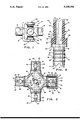
- FIG. 1 is a side elevational view of a universal joint assembly which embodies the present invention.
- FIG. 2 is an cross-sectional (in part), elevational face view of a cross member, showing only one bearing cup (of a set of four) positioned on one of the trunnions of the universal joint of FIG. 1.
- FIG. 3 is an enlarged view of a standpipe lubrication device constructed in accordance with the present invention, the upper half of the device depicted in cross-section.
- a universal joint assembly 10 provides a coupling for a pair of angularly offset, rotary drive and driven shafts 12 and 14, respectively.
- the assembly 10 incorporates a pair of yokes 16 and 18 which contain bearing cups 20 held in lugs 22 via retaining rings 24.
- bearing cups 20 are rotatably mounted on four trunnions (also variously called journals) 26 which extend radially from a central body 30 of a cross member 28 as shown.
- a lubrication passage 36 extends through the center of each radially extending trunnion 26, outwardly from an internal cavity 29 of the central body 30.
- the body 30 contains a lubricant fitting 37 having a pair of obliquely angled external nipples 38 and 40 designed to permit one-way flows of lubricant directly into the internal cavity 29, and hence to the passages 36.
- the assembly 10 is designed to be periodically relubricated for longevity and proper operation.
- Each passage 36 terminates into a lubrication cavity 42 in the extremity 27 of each trunnion 26.
- Each cavity 42 is defined by a counterbore 43 sized to hold adequate lubrication between periods of operation.
- the lubrication system provides for the grease to pass through the passages 36, into the cavities 42, and ultimately into the interior of the bearing cups 20.
- the extremities 27 of the trunnions 26 have grooves 44 which extend radially outwardly to facilitate flows of liquid grease.
- the grease travels through the grooves 44 to lubricate a plurality of needle bearings 32 situated between the interior cylindrical surface 23 of each cup and the exterior cylindrical surface 34 of each trunnion.
- the grease is retained within each cup by a double lip seal 46 (only one of which is shown) situated between each cup and trunnion.
- the typical universal joint assembly 10 will be subjected to periods of non-operation, wherein the assembly will remain at rest with one or two of the trunnions in an upper position relative to the others.
- the grease will have a tendency to drain down through the higher positioned passages 36 and into the low cup or cups 20 by force of gravity whenever joint rotation ceases.
- the grease cools, congeals, and become viscus prior to resumption of vehicular operation.
- the initial tendency is for the grease to remain in the cup or cups to which it has drained until it again becomes liquid.
- centrifugal force will act on the joint assembly 10, to retain the grease in that cup or cups.
- the present invention provides a standpipe lubrication device 50 which defines an elongate tubular body 52 having reversely identical first and second ends 54 and 56 extending along an axis "a--a".
- the body is adapted for insertion of either end into the lubrication passage 36 extending through each trunnion 26.
- Intermediate the first and second ends 54, 56 is a radially extending positioning flange 58.
- the flange is symmetrically positioned between the two ends, and operates to limit the amount insertion of the tubular body 52 to the length of either inserted end 54 or 56, as appropriate.
- Each counterbore 43 (FIG. 2) contains a frustoconical base 48 which interfaces with an associated lubrication passage 36.
- the flange 58 of each lubrication device 50 defines a pair of radially extending locator bases 57, each base facing one end 54 or 56 of the body 52.
- Each locator base 57 defines a circumferential edge 59 which makes a circular line contact with the base 48 of the counterbore 43.
- Such contact between the locator base 57 and associated counterbore base 48 is strictly for limiting insertion of an end 54, 56; i.e., for positioning. No lubrication sealing is effected nor required by such contact, as the latter function is carried out entirely by protuberances 70 and 72 as described hereafter.
- both ends 54 and 56 include pluralities of radially extending notches 64 and 66, respectively, in their respective extremities 60 and 62.
- the notches facilitate radial flows of liquid grease to the bearings even though the extremities 60, 62 of the device 50 may contact the internal bottom 21 of the bearing cup 20.
- Each end 54, 56 is defined by a length which extends between an extremity 60, 62 and a locator base 57 most proximal to that particular extremity.
- Axially distributed along the ends 54, 56 are pluralities of annular, deformable protuberances 70, 72, respectively.
- the protuberances are symmetrical both axially along and circumferentially about the axis "a--a" of the tubular body 52.
- the diameters of the protuberances are sized to be greater than both the diameters of the tubular body 52 and the passage 36 into which one end 54, 56 of the body is inserted.
- the protuberances are designed so as to be self-lockingly insertable; that is, the protuberances 70, 72, on respective ends 54 and 56, are arranged to present a frustoconical surface 80, 90 which faces away from the positioning flange 58 and toward the extremity 60 or 62 being inserted.
- Adjoining the frustoconical surfaces 80, 90 of respective ends 70 and 72 are cylindrical surfaces 82, 92, the latter defining radially extending annular surfaces or lips 84, 94 which face the positioning flange 58.
- the nature of the protuberance after insertion into a passage 36 is to resist forces tending to remove or dislodge the device 50 from the passage 36.
- the protuberances are preferably made of a moldable elastic material, such as a plastic or nylon particularly compounded for and characterized by dimensional heat stability.
- the protuberances are integral to the tubular body 52, having a diameter sufficiently greater than that of the body 52 to absorb tolerances between the passage 36 and the external diameter of the body 52.
- a moldable elastic material such as a plastic or nylon particularly compounded for and characterized by dimensional heat stability.
- the protuberances are integral to the tubular body 52, having a diameter sufficiently greater than that of the body 52 to absorb tolerances between the passage 36 and the external diameter of the body 52.
- Zytel® is made and sold under the tradename "Zytel®" by E.I. Du Pont de Nemours, Inc.
- either end 54 or 56 of the device 50 may conveniently be inserted into a passage 36, it will appreciated by those skilled in the art that the respective sets of lips 84 and 94 of the protuberances 70 and 72 will face opposite directions. It will be appreciated by those skilled in the art that the protuberances 70, 72 will be subjected to deformation upon insertion of the ends 54 and 56 into the passage 36. Thus either end 54, 56 will provide a frictional retention system adapted to absorb tolerance, and yet be capable of sealing against liquid lubrication flows between the body 52 and the lubrication passage 36 under a pre-determined range of dimensional variance between the latter structures.
- a prototype lubrication standpipe device 50 has a length of 1.31 inch.
- the positioning flange 58 has a diameter of 0.44 inch.
- Each tubular end 54, 56 has an overall outside diameter of 0.300 inch with a total permitted tolerance of 0.010 inch while the protuberances 70 and 72 are 0.330 inch, also with a permitted tolerance range of 0.010 inch.
- R radial dimensional difference
- the diameter of the counterbore 43 which defines the extremity of the lubrication cavity 42, is approximately 0.62 inch.
- the diameter of the internal passage 36 is 0.3135 inch with a tolerance of 0.013 of an inch.
- the cylindrical surface 82, 92 has an axial length of 0.020 inch.
- the adjoining frustoconical surfaces 80 and 90 extend at a 30 degree angle, measured with respect to axis "a--a”.
- the internal bore 51 extending through the body 52 has a diameter of 0.19 inch.
- the length of each end 54, 56 is 0.530 inch.
Landscapes
- Engineering & Computer Science (AREA)
- General Engineering & Computer Science (AREA)
- Mechanical Engineering (AREA)
- Rolling Contact Bearings (AREA)
- Sliding-Contact Bearings (AREA)
- Joints Allowing Movement (AREA)
Abstract
Description
Claims (11)
Priority Applications (8)
| Application Number | Priority Date | Filing Date | Title |
|---|---|---|---|
| US07/676,676 US5188564A (en) | 1991-03-28 | 1991-03-28 | Lubrication device for universal joint assembly |
| CA002059993A CA2059993A1 (en) | 1991-03-28 | 1992-01-24 | Lubrication device for universal joint assembly |
| BR929200422A BR9200422A (en) | 1991-03-28 | 1992-02-07 | LUBRICATION DEVICE FOR UNIVERSAL JOINT ASSEMBLY |
| EP92302234A EP0506274B1 (en) | 1991-03-28 | 1992-03-16 | Lubrication device for universal joint assembly |
| DE69200877T DE69200877T2 (en) | 1991-03-28 | 1992-03-16 | Lubrication device for universal joints. |
| JP4097455A JPH05118342A (en) | 1991-03-28 | 1992-03-25 | Lubricating device for universal joint assembly |
| MX9201405A MX9201405A (en) | 1991-03-28 | 1992-03-27 | LUBRICATION DEVICE FOR UNIVERSAL BOARD ASSEMBLY. |
| KR1019920005091A KR100226011B1 (en) | 1991-03-28 | 1992-03-27 | Lubrication device for universal joint assembly |
Applications Claiming Priority (1)
| Application Number | Priority Date | Filing Date | Title |
|---|---|---|---|
| US07/676,676 US5188564A (en) | 1991-03-28 | 1991-03-28 | Lubrication device for universal joint assembly |
Publications (1)
| Publication Number | Publication Date |
|---|---|
| US5188564A true US5188564A (en) | 1993-02-23 |
Family
ID=24715492
Family Applications (1)
| Application Number | Title | Priority Date | Filing Date |
|---|---|---|---|
| US07/676,676 Expired - Lifetime US5188564A (en) | 1991-03-28 | 1991-03-28 | Lubrication device for universal joint assembly |
Country Status (8)
| Country | Link |
|---|---|
| US (1) | US5188564A (en) |
| EP (1) | EP0506274B1 (en) |
| JP (1) | JPH05118342A (en) |
| KR (1) | KR100226011B1 (en) |
| BR (1) | BR9200422A (en) |
| CA (1) | CA2059993A1 (en) |
| DE (1) | DE69200877T2 (en) |
| MX (1) | MX9201405A (en) |
Cited By (13)
| Publication number | Priority date | Publication date | Assignee | Title |
|---|---|---|---|---|
| US5588915A (en) * | 1995-12-26 | 1996-12-31 | Dana Corporation | Seal and seal guard assembly for universal joint |
| US5660589A (en) * | 1995-12-26 | 1997-08-26 | Dana Corporation | Lubricant retaining valve for universal joint |
| US5718633A (en) * | 1995-03-09 | 1998-02-17 | Meritor Heavy Vehicle Systems, Llc | Universal joint wear indicator |
| US5868622A (en) * | 1995-02-21 | 1999-02-09 | The Zeller Corporation | Universal joint lubrication system |
| US6050899A (en) * | 1998-05-15 | 2000-04-18 | Neapco, Inc. | Sealing system for a universal joint assembly |
| US6102805A (en) * | 1995-02-21 | 2000-08-15 | Driveline Technologies, Inc. | Universal joint lubrication system |
| KR20010046375A (en) * | 1999-11-12 | 2001-06-15 | 송재인 | Bearing device with two degree of freedom |
| US20060009293A1 (en) * | 2004-07-07 | 2006-01-12 | Smith Johnny N | Lubrication system for a universal joint cross |
| US7118484B2 (en) * | 2000-12-06 | 2006-10-10 | Nsk Ltd. | Cross joint |
| KR200485475Y1 (en) * | 2016-09-29 | 2018-01-15 | 주식회사 센트랄 | Protection cap for a T-type nipple |
| CN111810547A (en) * | 2016-07-22 | 2020-10-23 | 戴振伟 | Cross shaft assembly and transmission shaft |
| CN114278679A (en) * | 2021-12-22 | 2022-04-05 | 浙江钱富万向节有限公司 | Universal joint with waste oil recovery structure |
| US20250083630A1 (en) * | 2023-09-11 | 2025-03-13 | Howard Fabbrini | Vehicle drive shaft grease system |
Families Citing this family (1)
| Publication number | Priority date | Publication date | Assignee | Title |
|---|---|---|---|---|
| FR2891346B1 (en) * | 2005-09-27 | 2007-12-14 | Gkn Driveline Sa Sa | CROSSBOW FOR CARDAN SEAL AND CORRESPONDING ASSEMBLY. |
Citations (8)
| Publication number | Priority date | Publication date | Assignee | Title |
|---|---|---|---|---|
| US895149A (en) * | 1905-05-17 | 1908-08-04 | Maurice E Blood | Universal joint. |
| US1492351A (en) * | 1921-05-14 | 1924-04-29 | H H Franklin Mfg Company | Lubricating means for motion-transmitting joints |
| US1949500A (en) * | 1931-03-14 | 1934-03-06 | Mechanics Universal Joint Comp | Universal joint |
| US3470711A (en) * | 1967-11-24 | 1969-10-07 | Dana Corp | Lubrication system for a universal joint |
| US4047396A (en) * | 1976-05-13 | 1977-09-13 | Rockwell International Corporation | Universal joint and cross therefor |
| USRE30790E (en) * | 1979-03-22 | 1981-11-10 | The Zeller Corporation | Universal joint lubrication |
| US4445875A (en) * | 1980-12-03 | 1984-05-01 | Matsui Universal Joint Manufacturing Company | Universal joint |
| US4650440A (en) * | 1984-03-24 | 1987-03-17 | Brd Company Limited | Lubrication of hookes universal joints |
Family Cites Families (3)
| Publication number | Priority date | Publication date | Assignee | Title |
|---|---|---|---|---|
| US3832865A (en) * | 1973-05-04 | 1974-09-03 | Zeller Corp | Universal joint lubrication |
| DE2841955C2 (en) * | 1978-09-27 | 1986-12-11 | Daimler-Benz Ag, 7000 Stuttgart | Universal joint, in particular for driven steering axles in motor vehicles |
| FR2519407B1 (en) * | 1982-01-07 | 1986-03-21 | Glaenzer Spicer Sa | LUBRICATION DEVICE, PARTICULARLY FOR CARDAN JOINT CROSSOVER |
-
1991
- 1991-03-28 US US07/676,676 patent/US5188564A/en not_active Expired - Lifetime
-
1992
- 1992-01-24 CA CA002059993A patent/CA2059993A1/en not_active Abandoned
- 1992-02-07 BR BR929200422A patent/BR9200422A/en not_active IP Right Cessation
- 1992-03-16 DE DE69200877T patent/DE69200877T2/en not_active Expired - Fee Related
- 1992-03-16 EP EP92302234A patent/EP0506274B1/en not_active Expired - Lifetime
- 1992-03-25 JP JP4097455A patent/JPH05118342A/en active Pending
- 1992-03-27 MX MX9201405A patent/MX9201405A/en not_active IP Right Cessation
- 1992-03-27 KR KR1019920005091A patent/KR100226011B1/en not_active Expired - Fee Related
Patent Citations (9)
| Publication number | Priority date | Publication date | Assignee | Title |
|---|---|---|---|---|
| US895149A (en) * | 1905-05-17 | 1908-08-04 | Maurice E Blood | Universal joint. |
| US1492351A (en) * | 1921-05-14 | 1924-04-29 | H H Franklin Mfg Company | Lubricating means for motion-transmitting joints |
| US1949500A (en) * | 1931-03-14 | 1934-03-06 | Mechanics Universal Joint Comp | Universal joint |
| US3470711A (en) * | 1967-11-24 | 1969-10-07 | Dana Corp | Lubrication system for a universal joint |
| US4047396A (en) * | 1976-05-13 | 1977-09-13 | Rockwell International Corporation | Universal joint and cross therefor |
| US4103512A (en) * | 1976-05-13 | 1978-08-01 | Rockwell International Corporation | Universal joint and cross therefor |
| USRE30790E (en) * | 1979-03-22 | 1981-11-10 | The Zeller Corporation | Universal joint lubrication |
| US4445875A (en) * | 1980-12-03 | 1984-05-01 | Matsui Universal Joint Manufacturing Company | Universal joint |
| US4650440A (en) * | 1984-03-24 | 1987-03-17 | Brd Company Limited | Lubrication of hookes universal joints |
Cited By (18)
| Publication number | Priority date | Publication date | Assignee | Title |
|---|---|---|---|---|
| US5868622A (en) * | 1995-02-21 | 1999-02-09 | The Zeller Corporation | Universal joint lubrication system |
| US6102805A (en) * | 1995-02-21 | 2000-08-15 | Driveline Technologies, Inc. | Universal joint lubrication system |
| US5718633A (en) * | 1995-03-09 | 1998-02-17 | Meritor Heavy Vehicle Systems, Llc | Universal joint wear indicator |
| US5588915A (en) * | 1995-12-26 | 1996-12-31 | Dana Corporation | Seal and seal guard assembly for universal joint |
| US5660589A (en) * | 1995-12-26 | 1997-08-26 | Dana Corporation | Lubricant retaining valve for universal joint |
| AU704602B2 (en) * | 1995-12-26 | 1999-04-29 | Dana Corporation | Lubricant retaining valve for universal joint |
| AU704889B2 (en) * | 1995-12-26 | 1999-05-06 | Dana Corporation | Seal and seal guard assembly for universal joint |
| US6050899A (en) * | 1998-05-15 | 2000-04-18 | Neapco, Inc. | Sealing system for a universal joint assembly |
| KR20010046375A (en) * | 1999-11-12 | 2001-06-15 | 송재인 | Bearing device with two degree of freedom |
| US7118484B2 (en) * | 2000-12-06 | 2006-10-10 | Nsk Ltd. | Cross joint |
| US20070026951A1 (en) * | 2000-12-06 | 2007-02-01 | Nsk Ltd. | Cross joint |
| US7357720B2 (en) | 2000-12-06 | 2008-04-15 | Nsk Ltd. | Cross joint |
| US20060009293A1 (en) * | 2004-07-07 | 2006-01-12 | Smith Johnny N | Lubrication system for a universal joint cross |
| US7140965B2 (en) | 2004-07-07 | 2006-11-28 | Torque-Traction Technologies Llc | Lubrication system for a universal joint cross |
| CN111810547A (en) * | 2016-07-22 | 2020-10-23 | 戴振伟 | Cross shaft assembly and transmission shaft |
| KR200485475Y1 (en) * | 2016-09-29 | 2018-01-15 | 주식회사 센트랄 | Protection cap for a T-type nipple |
| CN114278679A (en) * | 2021-12-22 | 2022-04-05 | 浙江钱富万向节有限公司 | Universal joint with waste oil recovery structure |
| US20250083630A1 (en) * | 2023-09-11 | 2025-03-13 | Howard Fabbrini | Vehicle drive shaft grease system |
Also Published As
| Publication number | Publication date |
|---|---|
| EP0506274B1 (en) | 1994-12-14 |
| DE69200877T2 (en) | 1995-04-27 |
| MX9201405A (en) | 1992-10-01 |
| KR920018395A (en) | 1992-10-22 |
| JPH05118342A (en) | 1993-05-14 |
| EP0506274A1 (en) | 1992-09-30 |
| BR9200422A (en) | 1992-12-01 |
| CA2059993A1 (en) | 1992-09-29 |
| DE69200877D1 (en) | 1995-01-26 |
| KR100226011B1 (en) | 1999-10-15 |
Similar Documents
| Publication | Publication Date | Title |
|---|---|---|
| US5188564A (en) | Lubrication device for universal joint assembly | |
| US7189162B2 (en) | Universal joint with thrust washer | |
| US5725431A (en) | Thrust washer for universal joint having preloading thrust surfaces | |
| US6855059B2 (en) | Universal joint with bearing cup retention thrust washer | |
| US6264566B1 (en) | Thrust washer for universal joint | |
| KR101088470B1 (en) | Universal joint with integrated seal deflector and retainer assembly | |
| US4702626A (en) | Sealing rolling bearing | |
| US6129634A (en) | Thrust washer for universal joint | |
| JPS60203502A (en) | Integral type wheel-bearing-seal assembly | |
| JPS59208220A (en) | Lubricating device for double row roller bearing turned at high speed | |
| US3832865A (en) | Universal joint lubrication | |
| EP0157565B1 (en) | Lubrication of hookes universal joints | |
| US4861315A (en) | Flexible internal universal joint seal | |
| US6837795B2 (en) | Universal joint with bearing cup retention seal assembly | |
| CN1957190A (en) | Universal joint washer baffle combination | |
| JPH0626527A (en) | Self-locking metallic cap, plastic bearing and self-locking metallic cap-plastic bearing cup-assembly | |
| AU657229B2 (en) | Universal joint lubricant retainer | |
| JP3483708B2 (en) | Universal joint lubrication system | |
| GB2307955A (en) | Bearing roller retainer for universal joint | |
| BRPI0401115B1 (en) | UNIVERSAL GASKET WASHER FOR RETAINING MANCAL CUP AND MOUNTING METHOD FOR A UNIVERSAL JOINT | |
| JPH09144762A (en) | Ball bearing, and pulley and fan provided with the ball bearing | |
| JPH0754665Y2 (en) | Universal joint | |
| JPS5855365B2 (en) | universal joint | |
| JPH0540626U (en) | Spider used for joins | |
| MXPA97005549A (en) | Torsion low-torque lubricant seal, hydrodinam |
Legal Events
| Date | Code | Title | Description |
|---|---|---|---|
| AS | Assignment |
Owner name: DANA CORPORATION, TOLEDO, OHIO A CORP. OF VIRGINIA Free format text: ASSIGNMENT OF ASSIGNORS INTEREST.;ASSIGNOR:KELLER, THOMAS J.;REEL/FRAME:005663/0066 Effective date: 19910328 |
|
| STCF | Information on status: patent grant |
Free format text: PATENTED CASE |
|
| FPAY | Fee payment |
Year of fee payment: 4 |
|
| FEPP | Fee payment procedure |
Free format text: PAYOR NUMBER ASSIGNED (ORIGINAL EVENT CODE: ASPN); ENTITY STATUS OF PATENT OWNER: LARGE ENTITY |
|
| FPAY | Fee payment |
Year of fee payment: 8 |
|
| AS | Assignment |
Owner name: SPICER DRIVESHAFT, INC., OHIO Free format text: ASSIGNMENT OF ASSIGNORS INTEREST;ASSIGNOR:DANA CORPORATION, A VIRGINIA CORPORATION;REEL/FRAME:011667/0621 Effective date: 20001221 |
|
| AS | Assignment |
Owner name: TORQUE-TRACTION TECHNOLOGIES, INC., OHIO Free format text: CHANGE OF NAME;ASSIGNOR:SPICER DRIVESHAFT, INC.;REEL/FRAME:014646/0042 Effective date: 20021231 |
|
| AS | Assignment |
Owner name: TORQUE-TRACTION TECHNOLOGIES, INC., OHIO Free format text: CHANGE OF NAME;ASSIGNOR:SPICER DRIVESHAFT, INC.;REEL/FRAME:013933/0631 Effective date: 20021231 |
|
| FPAY | Fee payment |
Year of fee payment: 12 |
|
| AS | Assignment |
Owner name: TORQUE-TRACTION TECHNOLOGIES LLC,OHIO Free format text: MERGER;ASSIGNOR:TORQUE-TRACTION TECHNOLOGY, INC.;REEL/FRAME:017240/0259 Effective date: 20060101 Owner name: TORQUE-TRACTION TECHNOLOGIES LLC, OHIO Free format text: MERGER;ASSIGNOR:TORQUE-TRACTION TECHNOLOGY, INC.;REEL/FRAME:017240/0259 Effective date: 20060101 |
|
| AS | Assignment |
Owner name: DANA AUTOMOTIVE SYSTEMS GROUP, LLC, OHIO Free format text: ASSIGNMENT OF ASSIGNORS INTEREST;ASSIGNOR:TORQUE-TRACTION TECHNOLOGIES, LLC;REEL/FRAME:020518/0949 Effective date: 20080131 Owner name: DANA AUTOMOTIVE SYSTEMS GROUP, LLC,OHIO Free format text: ASSIGNMENT OF ASSIGNORS INTEREST;ASSIGNOR:TORQUE-TRACTION TECHNOLOGIES, LLC;REEL/FRAME:020518/0949 Effective date: 20080131 |
|
| AS | Assignment |
Owner name: CITICORP USA, INC., NEW YORK Free format text: INTELLECTUAL PROPERTY REVOLVING FACILITY SECURITY AGREEMENT;ASSIGNORS:DANA HOLDING CORPORATION;DANA LIMITED;DANA AUTOMOTIVE SYSTEMS GROUP, LLC;AND OTHERS;REEL/FRAME:020859/0249 Effective date: 20080131 Owner name: CITICORP USA, INC.,NEW YORK Free format text: INTELLECTUAL PROPERTY REVOLVING FACILITY SECURITY AGREEMENT;ASSIGNORS:DANA HOLDING CORPORATION;DANA LIMITED;DANA AUTOMOTIVE SYSTEMS GROUP, LLC;AND OTHERS;REEL/FRAME:020859/0249 Effective date: 20080131 Owner name: CITICORP USA, INC., NEW YORK Free format text: INTELLECTUAL PROPERTY TERM FACILITY SECURITY AGREEMENT;ASSIGNORS:DANA HOLDING CORPORATION;DANA LIMITED;DANA AUTOMOTIVE SYSTEMS GROUP, LLC;AND OTHERS;REEL/FRAME:020859/0359 Effective date: 20080131 Owner name: CITICORP USA, INC.,NEW YORK Free format text: INTELLECTUAL PROPERTY TERM FACILITY SECURITY AGREEMENT;ASSIGNORS:DANA HOLDING CORPORATION;DANA LIMITED;DANA AUTOMOTIVE SYSTEMS GROUP, LLC;AND OTHERS;REEL/FRAME:020859/0359 Effective date: 20080131 |