US5188430A - Structure for a golf cart wheel shaft - Google Patents
Structure for a golf cart wheel shaft Download PDFInfo
- Publication number
- US5188430A US5188430A US07/813,096 US81309691A US5188430A US 5188430 A US5188430 A US 5188430A US 81309691 A US81309691 A US 81309691A US 5188430 A US5188430 A US 5188430A
- Authority
- US
- United States
- Prior art keywords
- bushing
- pair
- shaft
- members
- tubular
- Prior art date
- Legal status (The legal status is an assumption and is not a legal conclusion. Google has not performed a legal analysis and makes no representation as to the accuracy of the status listed.)
- Expired - Fee Related
Links
Images


Classifications
-
- B—PERFORMING OPERATIONS; TRANSPORTING
- B60—VEHICLES IN GENERAL
- B60B—VEHICLE WHEELS; CASTORS; AXLES FOR WHEELS OR CASTORS; INCREASING WHEEL ADHESION
- B60B37/00—Wheel-axle combinations, e.g. wheel sets
- B60B37/10—Wheel-axle combinations, e.g. wheel sets the wheels being individually rotatable around the axles
Definitions
- a conventional golf cart wheel shaft shown in FIG. 3 comprises two ball bearings 11, each properly fixed in spaced relation within a central hole 121 of a shaft supporting cylinder 12.
- the ball bearings 11 support and position a shaft bushing 13, from which a shaft 14 extends.
- the shaft 14 has a threaded hole 141 at the outer end for receipt of a thumb screw 15 with a head 151 for coupling one to another so as to make the shaft bushing 13 move together with the shaft 14.
- the conventional golf cart wheel shaft has been found to have the following drawbacks.
- the bearings 11 and the shaft bushing 13 are knocked manually into their position during assembly thereof, but the shaft 14 often becomes biased because of uneven forces applied thereto when it is struck, resulting in unsmooth rolling of the wheel.
- the bearings 11 and the shaft bushing 13 are made of metal, having high cost, but without providing a long service life.
- the balls in the bearings 11 can be prevented from proper rotation by dirt and sand after a period of use on a golf course, which is detrimental to rotation of the wheel.
- This invention has been devised to supply a structure for a golf cart wheel shaft to overcome the drawbacks mentioned above.
- the structure for a golf cart wheel shaft in the present invention has been designed to have the following advantages.
- the shaft bushing is provided with clamping fingers so as to firmly combine the shaft bushing with the shaft, and they can be made as a separate unit to save time and work, and resulting in lower cost.
- Hole bushings are securely and firmly fixed within the hub of the wheel by insertion while the hole bushings are soft, not yet hardened, as when they are just coming out of the mold. The hole bushings are thereby able to keep the shaft rotatably stabilized after the hole bushings have hardened.
- the elastic clamping fingers can be operated quickly to couple the shaft and the shaft bushing all together in their operative position to rotate synchronously, upgrading the effectiveness of assembly.
- the hole bushings and the shaft bushing are assembled with an extremely close fit so that dirt or sand cannot easily go into the gap therebetween, so that the wheel can rotate very smoothly.
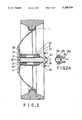
- FIG. 2 is a cross-sectional view of the structure for a golf cart wheel shaft in the present invention
- the two hole bushings 2, 2 are each respectively provided with a flange 21 at the outer end, a plurality of annular projections 22 and a central bore 23.
- the two hole bushings 2, 2 are first forced into respective opposing ends of the central bore 111 of the hub 11, while the bushings 2, 2 are still soft, immediately as they are taken out of a mold. This assembly is left to cool off, with the annular projections 22 firmly engaged within the annular grooves 112. Next, the shaft bushing 3 is inserted through the two hole bushings 2, 2 with the vertical edge of the sloped ring shaped portion 31 and the fitting ring portion 33 each being in flush contact with the outer end surface of a respective hole bushing, thereby maintaining the position of the shaft bushing 3, but allowing it to rotate within the central bore 23 of each of the hole bushings 2, 2.
Landscapes
- Engineering & Computer Science (AREA)
- Mechanical Engineering (AREA)
- Handcart (AREA)
Abstract
Description
Claims (1)
Priority Applications (1)
| Application Number | Priority Date | Filing Date | Title |
|---|---|---|---|
| US07/813,096 US5188430A (en) | 1991-12-24 | 1991-12-24 | Structure for a golf cart wheel shaft |
Applications Claiming Priority (1)
| Application Number | Priority Date | Filing Date | Title |
|---|---|---|---|
| US07/813,096 US5188430A (en) | 1991-12-24 | 1991-12-24 | Structure for a golf cart wheel shaft |
Publications (1)
| Publication Number | Publication Date |
|---|---|
| US5188430A true US5188430A (en) | 1993-02-23 |
Family
ID=25211437
Family Applications (1)
| Application Number | Title | Priority Date | Filing Date |
|---|---|---|---|
| US07/813,096 Expired - Fee Related US5188430A (en) | 1991-12-24 | 1991-12-24 | Structure for a golf cart wheel shaft |
Country Status (1)
| Country | Link |
|---|---|
| US (1) | US5188430A (en) |
Cited By (17)
| Publication number | Priority date | Publication date | Assignee | Title |
|---|---|---|---|---|
| US5277480A (en) * | 1992-12-28 | 1994-01-11 | Sunshon Molding Co., Ltd. | Wheel unit for a baby carriage |
| US5358314A (en) * | 1992-06-15 | 1994-10-25 | Claber S.P.A. | Wheel and rotation shaft assembly for a hose-winding cart |
| US5452381A (en) * | 1993-02-23 | 1995-09-19 | Guerra; Antonio | Wheel bushing for bicycle |
| US5520705A (en) * | 1991-03-01 | 1996-05-28 | E. I. Du Pont De Nemours And Company | Surface treated aramid fibers and a process for making them |
| ES2116843A1 (en) * | 1994-06-24 | 1998-07-16 | Guerra Navas Antonio | Bush for single-arm bicycle wheels |
| US6099083A (en) * | 1998-10-23 | 2000-08-08 | Graco Children's Products Inc. | Retention mechanism for use with an axle assembly |
| US6409284B1 (en) * | 2001-06-25 | 2002-06-25 | Chin Sung Ko | Connecting structure of a wheel of a golf carrier |
| US6508518B1 (en) | 1996-08-07 | 2003-01-21 | Robert H. Owen | Hubcap locking device |
| US6561593B2 (en) * | 2000-10-04 | 2003-05-13 | Craig Richard Godwin | Locking hub and wheel assembly |
| US6595531B2 (en) * | 2000-06-23 | 2003-07-22 | Magic Toys Do Brasil Ind. E Com. Ltda | Unit to replace the rear metal axle in children's tricycles |
| US6666526B1 (en) * | 2001-03-21 | 2003-12-23 | Spartech Corporation | Molded wheel assembly |
| US6682152B2 (en) * | 2000-09-25 | 2004-01-27 | Freedom Designs Incorporated | Secure wheel locking system |
| US20050134019A1 (en) * | 2003-12-22 | 2005-06-23 | Salvio Plana | Stabilizer training wheel with integral suspension |
| US20060226631A1 (en) * | 2005-03-21 | 2006-10-12 | Holroyd James A | Vehicle axle mounting |
| US7165815B1 (en) * | 2004-04-12 | 2007-01-23 | Li-Ting Huang | Wheel assembly for garden shears |
| US20070296263A1 (en) * | 2005-08-02 | 2007-12-27 | Smith David S | Coupling Assembly |
| US20120074663A1 (en) * | 2010-09-29 | 2012-03-29 | Cascade Engineering, Inc. | Wheel assembly for trash/recycling cart |
Citations (8)
| Publication number | Priority date | Publication date | Assignee | Title |
|---|---|---|---|---|
| US1375223A (en) * | 1919-08-09 | 1921-04-19 | Elmer E Mcintyre | Interchangeable hub for motor-vehicles |
| US2532605A (en) * | 1947-03-10 | 1950-12-05 | Castleberry Jack | Automobile axle |
| DE1505849A1 (en) * | 1964-01-18 | 1969-04-03 | Johann Wilden | Detachable attachment of a wheel, especially a stroller wheel, on an axle |
| FR2403214A1 (en) * | 1977-09-20 | 1979-04-13 | Lefevere Didier | Road wheel construction for trailers - has hollow beaded rim supported by two bolted coned parts on twin bearings with spacer and locking collars |
| GB2110609A (en) * | 1981-11-17 | 1983-06-22 | British Castors Ltd | A rotatable member |
| FR2607754A1 (en) * | 1986-12-03 | 1988-06-10 | Haco Rollen Vertrieb | Device for fixing a wheel body on the ends of axles of machines which are to be displaced, for example rubbish bins or the like |
| DE3811757A1 (en) * | 1988-04-08 | 1989-10-26 | Tolges Kunststoffverarbeitung | Device for connecting a wheel rim to an axle of a wheel |
| US5042882A (en) * | 1990-03-01 | 1991-08-27 | Deere & Company | Mower deck wheel bearing seal mechanism |
-
1991
- 1991-12-24 US US07/813,096 patent/US5188430A/en not_active Expired - Fee Related
Patent Citations (8)
| Publication number | Priority date | Publication date | Assignee | Title |
|---|---|---|---|---|
| US1375223A (en) * | 1919-08-09 | 1921-04-19 | Elmer E Mcintyre | Interchangeable hub for motor-vehicles |
| US2532605A (en) * | 1947-03-10 | 1950-12-05 | Castleberry Jack | Automobile axle |
| DE1505849A1 (en) * | 1964-01-18 | 1969-04-03 | Johann Wilden | Detachable attachment of a wheel, especially a stroller wheel, on an axle |
| FR2403214A1 (en) * | 1977-09-20 | 1979-04-13 | Lefevere Didier | Road wheel construction for trailers - has hollow beaded rim supported by two bolted coned parts on twin bearings with spacer and locking collars |
| GB2110609A (en) * | 1981-11-17 | 1983-06-22 | British Castors Ltd | A rotatable member |
| FR2607754A1 (en) * | 1986-12-03 | 1988-06-10 | Haco Rollen Vertrieb | Device for fixing a wheel body on the ends of axles of machines which are to be displaced, for example rubbish bins or the like |
| DE3811757A1 (en) * | 1988-04-08 | 1989-10-26 | Tolges Kunststoffverarbeitung | Device for connecting a wheel rim to an axle of a wheel |
| US5042882A (en) * | 1990-03-01 | 1991-08-27 | Deere & Company | Mower deck wheel bearing seal mechanism |
Cited By (21)
| Publication number | Priority date | Publication date | Assignee | Title |
|---|---|---|---|---|
| US5520705A (en) * | 1991-03-01 | 1996-05-28 | E. I. Du Pont De Nemours And Company | Surface treated aramid fibers and a process for making them |
| US5358314A (en) * | 1992-06-15 | 1994-10-25 | Claber S.P.A. | Wheel and rotation shaft assembly for a hose-winding cart |
| US5277480A (en) * | 1992-12-28 | 1994-01-11 | Sunshon Molding Co., Ltd. | Wheel unit for a baby carriage |
| US5452381A (en) * | 1993-02-23 | 1995-09-19 | Guerra; Antonio | Wheel bushing for bicycle |
| ES2116843A1 (en) * | 1994-06-24 | 1998-07-16 | Guerra Navas Antonio | Bush for single-arm bicycle wheels |
| US6508518B1 (en) | 1996-08-07 | 2003-01-21 | Robert H. Owen | Hubcap locking device |
| US6099083A (en) * | 1998-10-23 | 2000-08-08 | Graco Children's Products Inc. | Retention mechanism for use with an axle assembly |
| US6595531B2 (en) * | 2000-06-23 | 2003-07-22 | Magic Toys Do Brasil Ind. E Com. Ltda | Unit to replace the rear metal axle in children's tricycles |
| US6682152B2 (en) * | 2000-09-25 | 2004-01-27 | Freedom Designs Incorporated | Secure wheel locking system |
| US6561593B2 (en) * | 2000-10-04 | 2003-05-13 | Craig Richard Godwin | Locking hub and wheel assembly |
| US6666526B1 (en) * | 2001-03-21 | 2003-12-23 | Spartech Corporation | Molded wheel assembly |
| US6409284B1 (en) * | 2001-06-25 | 2002-06-25 | Chin Sung Ko | Connecting structure of a wheel of a golf carrier |
| US20050134019A1 (en) * | 2003-12-22 | 2005-06-23 | Salvio Plana | Stabilizer training wheel with integral suspension |
| US7032916B2 (en) | 2003-12-22 | 2006-04-25 | Brevets Futek-Msm Ltee | Stabilizer training wheel with integral suspension |
| US7165815B1 (en) * | 2004-04-12 | 2007-01-23 | Li-Ting Huang | Wheel assembly for garden shears |
| US20060226631A1 (en) * | 2005-03-21 | 2006-10-12 | Holroyd James A | Vehicle axle mounting |
| US7690668B2 (en) * | 2005-03-21 | 2010-04-06 | Polaris Industries, Inc. | Vehicle axle mounting |
| US20070296263A1 (en) * | 2005-08-02 | 2007-12-27 | Smith David S | Coupling Assembly |
| US7390068B2 (en) * | 2005-08-02 | 2008-06-24 | The Scott Fetzer Company | Coupling assembly for wheel and axle |
| US20120074663A1 (en) * | 2010-09-29 | 2012-03-29 | Cascade Engineering, Inc. | Wheel assembly for trash/recycling cart |
| US8444228B2 (en) * | 2010-09-29 | 2013-05-21 | Cascade Engineering, Inc. | Wheel assembly for trash/recycling cart |
Similar Documents
| Publication | Publication Date | Title |
|---|---|---|
| US5188430A (en) | Structure for a golf cart wheel shaft | |
| US5347681A (en) | Releasable fifth wheel caster for skateboards | |
| CA1056745A (en) | Roller assembly with improved mounting means | |
| US5594974A (en) | Releasable caster | |
| US5895188A (en) | Form panel quick fastener | |
| US20060076738A1 (en) | Quick change coupler | |
| US5072880A (en) | Sectional rod bearing for fussball game structure | |
| DE9011187U1 (en) | Axial locking for the rotor shaft of an electric motor | |
| US6412373B1 (en) | Operating tool having shanks turnable relative to one another | |
| US4674355A (en) | Crankhandle structure | |
| JPH09505226A (en) | Single bearing skate wheel core | |
| EP0344822A3 (en) | Removable ball joint | |
| US5249881A (en) | Telescoping arm apparatus | |
| US5685549A (en) | Chuck assembly for a tool bit | |
| US4138863A (en) | Universal joint cross with adjustable bearing cups | |
| JP2661697B2 (en) | Swivel joint | |
| US6443037B1 (en) | Screwdriver grip structure | |
| US6322156B1 (en) | Wheel assembly of luggage | |
| US4978175A (en) | Device for coupling a wheel to a golf club carrier | |
| AU756662B2 (en) | In-line skate wheel axle assembly and frame | |
| EP0856339A2 (en) | Quick release In-Line skate wheel axle | |
| JPS633281Y2 (en) | ||
| US5916066A (en) | Wheel assembly adapted to be mounted on a wheel-bearing tube of an exerciser without the need for a locking bolt | |
| KR0128661Y1 (en) | A volume knob combination structure of car audio | |
| KR200282045Y1 (en) | Reel seat for fishing rod |
Legal Events
| Date | Code | Title | Description |
|---|---|---|---|
| AS | Assignment |
Owner name: SUNSHON MOLDING CO., LTD. Free format text: ASSIGNMENT OF ASSIGNORS INTEREST.;ASSIGNOR:CHIU, HSIU-HUI;REEL/FRAME:005971/0134 Effective date: 19920110 Owner name: SUNSHON MOLDING CO., LTD., TAIWAN Free format text: ASSIGNMENT OF ASSIGNORS INTEREST;ASSIGNOR:CHIU, HSIU-HUI;REEL/FRAME:005971/0134 Effective date: 19920110 |
|
| REMI | Maintenance fee reminder mailed | ||
| LAPS | Lapse for failure to pay maintenance fees | ||
| FP | Lapsed due to failure to pay maintenance fee |
Effective date: 20010223 |
|
| STCH | Information on status: patent discontinuation |
Free format text: PATENT EXPIRED DUE TO NONPAYMENT OF MAINTENANCE FEES UNDER 37 CFR 1.362 |