US5185509A - Robotic arm tool mounting apparatus - Google Patents
Robotic arm tool mounting apparatus Download PDFInfo
- Publication number
- US5185509A US5185509A US07/657,564 US65756491A US5185509A US 5185509 A US5185509 A US 5185509A US 65756491 A US65756491 A US 65756491A US 5185509 A US5185509 A US 5185509A
- Authority
- US
- United States
- Prior art keywords
- soldering
- unit
- soldering apparatus
- circuit board
- pads
- Prior art date
- Legal status (The legal status is an assumption and is not a legal conclusion. Google has not performed a legal analysis and makes no representation as to the accuracy of the status listed.)
- Expired - Fee Related
Links
- 238000005476 soldering Methods 0.000 claims abstract description 83
- 239000012530 fluid Substances 0.000 claims abstract description 12
- 229910000679 solder Inorganic materials 0.000 claims description 24
- 238000004891 communication Methods 0.000 claims description 4
- 230000008878 coupling Effects 0.000 claims description 2
- 238000010168 coupling process Methods 0.000 claims description 2
- 238000005859 coupling reaction Methods 0.000 claims description 2
- 238000010438 heat treatment Methods 0.000 claims 1
- 230000013011 mating Effects 0.000 claims 1
- 230000000295 complement effect Effects 0.000 abstract description 3
- 238000006243 chemical reaction Methods 0.000 abstract description 2
- 239000004020 conductor Substances 0.000 description 14
- 238000000034 method Methods 0.000 description 13
- 238000010276 construction Methods 0.000 description 6
- 239000000758 substrate Substances 0.000 description 5
- 230000000712 assembly Effects 0.000 description 4
- 238000000429 assembly Methods 0.000 description 4
- RYGMFSIKBFXOCR-UHFFFAOYSA-N Copper Chemical compound [Cu] RYGMFSIKBFXOCR-UHFFFAOYSA-N 0.000 description 3
- XAGFODPZIPBFFR-UHFFFAOYSA-N aluminium Chemical compound [Al] XAGFODPZIPBFFR-UHFFFAOYSA-N 0.000 description 3
- 229910052782 aluminium Inorganic materials 0.000 description 3
- 229910052802 copper Inorganic materials 0.000 description 3
- 239000010949 copper Substances 0.000 description 3
- 239000011324 bead Substances 0.000 description 2
- 239000000463 material Substances 0.000 description 2
- 239000007769 metal material Substances 0.000 description 2
- 239000004809 Teflon Substances 0.000 description 1
- 229920006362 Teflon® Polymers 0.000 description 1
- 229910010293 ceramic material Inorganic materials 0.000 description 1
- 239000011248 coating agent Substances 0.000 description 1
- 238000000576 coating method Methods 0.000 description 1
- 230000006835 compression Effects 0.000 description 1
- 238000007906 compression Methods 0.000 description 1
- 230000000694 effects Effects 0.000 description 1
- 238000005516 engineering process Methods 0.000 description 1
- 239000003562 lightweight material Substances 0.000 description 1
- 238000007567 mass-production technique Methods 0.000 description 1
- 238000012986 modification Methods 0.000 description 1
- 230000004048 modification Effects 0.000 description 1
- 239000012811 non-conductive material Substances 0.000 description 1
- 239000004033 plastic Substances 0.000 description 1
- 230000000284 resting effect Effects 0.000 description 1
- 239000007787 solid Substances 0.000 description 1
- 238000003466 welding Methods 0.000 description 1
Images


Classifications
-
- B—PERFORMING OPERATIONS; TRANSPORTING
- B23—MACHINE TOOLS; METAL-WORKING NOT OTHERWISE PROVIDED FOR
- B23K—SOLDERING OR UNSOLDERING; WELDING; CLADDING OR PLATING BY SOLDERING OR WELDING; CUTTING BY APPLYING HEAT LOCALLY, e.g. FLAME CUTTING; WORKING BY LASER BEAM
- B23K3/00—Tools, devices, or special appurtenances for soldering, e.g. brazing, or unsoldering, not specially adapted for particular methods
- B23K3/02—Soldering irons; Bits
- B23K3/03—Soldering irons; Bits electrically heated
-
- B—PERFORMING OPERATIONS; TRANSPORTING
- B23—MACHINE TOOLS; METAL-WORKING NOT OTHERWISE PROVIDED FOR
- B23K—SOLDERING OR UNSOLDERING; WELDING; CLADDING OR PLATING BY SOLDERING OR WELDING; CUTTING BY APPLYING HEAT LOCALLY, e.g. FLAME CUTTING; WORKING BY LASER BEAM
- B23K3/00—Tools, devices, or special appurtenances for soldering, e.g. brazing, or unsoldering, not specially adapted for particular methods
- B23K3/08—Auxiliary devices therefor
- B23K3/087—Soldering or brazing jigs, fixtures or clamping means
Definitions
- This invention relates in general to a robotic arm tool mounting apparatus and a method of using same. It more particularly relates to a such an apparatus for facilitating in a more accurate manner, robotic arm operations, such as soldering operations for integrated circuit devices.
- an electronic device or component to be installed is 1) retrieved from a lead die machine by a pick and place unit; 2) transported to a location in close proximity to a device placement site; 3) visualized and aligned so the leads of the device can be accurately placed on the pads of the printed circuit board; 4) placed on the pads of the printed circuit board; and 5) secured to the printed circuit board pads by applying heat to solder pre-deposited on the pads.
- Such a hot bar reflow soldering system typically employs a robotic system including a robotic arm for moving selectively the electronic component relative to the printed circuit board.
- a soldering head mounted on the end of the robotic arm may include a pick and place unit for holding and carrying the electronic component for placement on a soldering site, such as the pads of a printed circuit board.
- the head also includes a soldering arrangement including a reflow soldering hot bar unit, for soldering the leads of the component to the pads of a printed circuit board.
- An important aspect in a reflow soldering system is the accurate placement and soldering of the leads of a device to the pad of the circuit board to establish proper solder connections for electrical continuity.
- improper solder connections can result.
- costly and unwanted rejects of the assembled circuit board can occur.
- Integrated reflow hot bar soldering heads are well known in the prior art.
- prior art systems utilized for the placement and assembly of fine pitch devices to printed circuit board substrates have proven less than totally satisfactory in that they have not successfully reduced or substantially eliminated non-coplanarity problems between the leads of the device and the substrate surface.
- conventional large scale fine pitch devices are generally rectangular in shape with groups of fine pitch leads extending from all four sides of the body of the device.
- this type of fine pitch device configuration requires a hot bar head with a set of hot bars configured in a generally rectangular configuration for engaging simultaneously all the leads of the electronic device.
- an operator of the robotic control unit is able to visually align the leads of the electronic device by adjusting their orientation relative to the pads of the printed circuit board. Such adjustments are in coplanar X,Y directions and rotatively in a ⁇ (z) direction perpendicular to the X,Y planes.
- solder on the pads may liquify non-uniformly and unevenly.
- the soldering head will sink downwardly into the liquified solder but will also remain stationary against the solid solder.
- the principal object of the present invention is to provide a hot bar soldering system and head and method for accurately placing the leads of a fine pitch device in alignment with the pads of a corresponding printed circuit board, and for accurately soldering the fine pitch leads to the pads of the printed circuit board without the introduction of any substantial misalignment or improper soldered connections.
- Another object of the present invention is to provide such a new and improved system and head which is relatively simple in construction and very convenient to use, and which can be manufactured at a relatively low cost.
- an integrated soldering head having a truncated semi-spherical shaped protuberance and complementary shaped socket.
- the protuberance and socket define a universal joint to provide a gimballing action relative to the center point of an operative piece such as a printed circuit board.
- a supply of fluid under pressure is directed between the protuberance and the socket to reduce friction between their respective surfaces to reduce reaction on the delicate robotic arm as the head settles in place. Any unwanted axial x-y shift by the robotic unit for complying with a non-coplanar printed circuit board is prevented during placement of an electronic device on a corresponding printed circuit board as well as during the reflow soldering process.
- the method of preventing lead to pad misalignment includes the steps of using a robotic unit and integrated hot bar soldering head for movement and soldering purposes, causing the robotic unit to move the integrated hot bar soldering head into contact with a fine pitch electronic device.
- FIG. 1 is a partly fragmentary pictorial view of a hot bar reflow soldering system, including a hot bar reflow soldering head, which system and head are each constructed in accordance with the present invention, and which is shown operatively associated with a printed circuit board assembly and a robotic control unit shown fragmentarily, for illustrative purposes;
- FIG. 2 is an exploded pictorial view of the hot bar reflow soldering head of FIG. 1;
- FIG. 2a is a pictorial view of the hot bar reflow soldering head of FIG. 1 in an assembled configuration
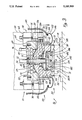
- FIG. 3 is a greatly enlarged, partially diagrammatic longitudinal sectional view of the hot bar reflow soldering head taken along the line 3--3 of FIG. 2a;
- FIG. 4 is a diagrammatic, partly cut away view of the upper portion of the hot bar reflow soldering head of FIG. 2;
- FIG. 5 is a greatly enlarged fragmentary partially diagrammatic longitudinal sectional view of a portion of the hot bar reflow soldering head of FIG. 2a taken substantially along line 5--5.
- FIG. 1 there is shown a hot bar reflow soldering system 10 which is constructed in accordance with the present invention.
- the system 10 of the present invention enables a fine pitch circuit component, such as an integrated circuit device 12, to be positioned more accurately on a printed circuit board, such as a printed circuit board 14, by eliminating, or at least greatly reducing, misalignments associated with non-coplanarity problems between the leads of the circuit device, shown generally at 13, and the pads on the printed circuit board, shown generally at 15 (FIG. 3).
- the hot bar reflow soldering system 10 includes an integrated reflow soldering head assembly 16 which is adapted to be attached removably to a robotic unit 18 through a robotic tool adaptor 20, each forming part of the soldering system 10.
- the robotic unit 18 and the robotic tool adaptor 20 are more fully described in the above mentioned copending U.S. patent application Ser. No. 07/657,563.
- the reflow soldering head assembly 16 also includes a holding unit 30 and a soldering unit 35 respectively.
- the reflow soldering head assembly 16 is an over-center device adapted to couple the downwardly directed forces of the robotic unit 18 in an evenly distributed manner to the leads 13 of the circuit device 12.
- the leads 13 of the circuit device 12 can engage the pads of the printed circuit board 14 without introducing any substantial lead to pad misalignment due to printed circuit board non-coplanarity problems.
- the reflow soldering head assembly 16 also includes an air activated gimballed joint, shown generally at 40, (FIG. 3) for reducing, if not eliminating entirely, unwanted and undesired x-y axial shifts in the robotic unit 18 for complying with a non-coplanar printed circuit board.
- the gimballed joint 40 enables the soldering unit 35 to move in a pivoting rockable manner for maintaining proper tolerance control without the need for x-y axial shifts in the robotic unit 18.
- bonding of the leads 13 to the pads 15 of the printed circuit board 14 can be achieved in a more reliable and accurate manner.
- the robotic unit 18 causes the holding unit 30 (FIG. 3) of the reflow soldering head assembly 16 to firmly secure a circuit device, such as device 12, for transportation to a printed circuit board, such as board 15.
- a circuit device such as device 12
- the robotic unit 18 causes the circuit device 12 to be moved rectilinearly downwardly into engagement with the printed circuit board 12. Assuming the printed circuit board 14 is not coplanar with the leads 13 of the circuit device 12, the leads of the device 12 will initially come into engagement with their corresponding sets of pads in an uneven or non-parallel manner.
- soldering unit 35 The resulting forces directed against the leads 13 via the downward travel of the robotic unit 18 will cause the soldering unit 35 to pivot rockably about its longitudinal center relative to the gimballed joint 40 to comply with the non-coplanarity of the board.
- This gimballed action occurs relative to a center point, such as a center point shown generally at A (FIG. 3) disposed on the printed circuit board surface in alignment with the geometric center of the body portion of the electronic device being placed on the board 14.
- the soldering head assembly 16 is able to pivot about the center of the circuit device 12 and independently of the robotic unit 18, thereby eliminating any x-y axial shifts on the part of the robotic unit 18 because of non-coplanarity problems.
- the robotic unit 18 continues in its downward path of travel, corresponding pivotal adjustments are made by the soldering unit 35 until all of the leads of the circuit device 12 firmly engage the pads of the printed circuit board 14.
- the robotic unit 18 then causes the soldering unit 35 to heat the pads of the printed circuit board 14 to soldering temperatures so that solder pre-deposited solder shown generally at S1 and S2 on the pads 15 of the printed circuit board 14 will begin to reflow.
- the robotic unit 18 continues to direct a downward force against the leads of the device 12 and the pads of the board 14, respectively.
- solder S1 solder S1
- solder S2 solder S1
- the gimballed action of the joint 40 relative to robotic unit 18 permits the soldering unit 35 to adjust movably so that proper tolerance controls are maintained between the circuit leads relative to the pads of the printed circuit board.
- the head assembly 16 includes an upper head section, shown generally at 51, and a lower head section shown generally at 53.
- the upper head section 51 and the lower head section 53 are mounted movably together to facilitate a rotative pivotal rocking motion.
- the upper head section 51 is mounted fixedly to the robotic tool adapter 20 by means not shown, while the lower head section 53 is mounted movably relative to the upper head section 51.
- the upper head section 51 includes a centrally disposed truncated semi-spherical recess or socket 42 that is dimensioned to receive a complementary shaped centrally disposed protuberance 44 extending upwardly from the upper surface of the lower head section 53.
- the socket 42 and protuberance 44 cooperate together to define the gimballed universal joint, shown generally at 40.
- the upper head section 51 generally has a unitary construction and is composed of a light weight metallic material, such as aluminum for helping to minimize the load carried or supported by the robotic unit 18.
- the upper head section 51 includes a flat rectangularly shaped body portion 52 and a set of four integrally connected outwardly projecting raised arms 55-58.
- the arms 55-58 are connected at the four corner portions 59-62 respectively of the body 52.
- the arms 55-58 are adapted to receive and support a corresponding set of spring assemblies, such as assemblies 65-68 respectively.
- each spring assembly 65-68 includes a spring 75-78 respectively, mounted removably between the upper head section 51 and the lower head section 53 for helping to facilitate their relative movement and for suspending resiliently the lower head section 53 from the upper head section 51 in a movable manner.
- the arms 55-58 are substantially identical and the spring assemblies 65-68 are substantially identical, only arm 55 and spring assembly 65 will be described hereinafter in greater detail.
- the arm 55 includes a generally rectangularly shaped spring mounting member 63 integrally connected to a generally triangularly shaped tool adaptor mounting member 64.
- the tool adaptor mounting member 64 is integrally connected to the body portion 52 at its corner 59.
- a threaded aperture 69 is centrally disposed in the upper surface of member 64 and extends perpendicularly downwardly into the body portion 52.
- the aperture 69 is dimensioned to receive a threaded mounting bolt (not shown) for securing the upper head section 51 to the robotic tool adaptor 20.
- a bore 70 is centrally disposed in the top surface of member 63 adjacent to the distal end of the arm 55.
- the bore 70 is dimensioned to receive one of the spring assemblies, such as the assembly 65.
- the body portion 52 of the upper head section 51 includes a large centrally disposed annular recess 71 in its upper surface 73 with a centrally disposed annular bore 75 therein for receiving a portion of the holding unit 30.
- the socket 42 is centrally disposed in the lower surface 77 of the body portion 52.
- Socket 42 includes a plurality of spaced apart socket outlets, such as outlets 79-86, equally distributed about the annular bore 75. Each of the plurality of spaced apart outlets, such as outlets 79-86 are in fluid communication with an air manifold, shown generally at 90, disposed within the upper head section 51.
- the air manifold 90 receives a supply of air under pressure from the robotic unit 18 so the air under pressure can be distributed to the socket outlets, such as the outlets 79-86. As the air under pressure exits the manifold 90 via the outlets 79-86 it forms an air cushion between the socket 42 and the protuberance 44. In this regard, the air cushion causes the protuberance 44 to float within the socket 42 for facilitating the movement of the lower head section 53 relative to the upper head section 51 by creating a low friction joint between their respective surfaces.
- the low friction joint between the socket 42 and the protuberance 44 is formed by an air cushion, it will be understood by those skilled in the art that other forms of low friction joints are contemplated within the scope of this invention, such as by coating the socket 42 and protuberance 44 with a teflon material.
- the air manifold 90 generally includes four pairs of air passageways 91-98 for distributing air under pressure to the plurality of outlets, such as outlets 79-86.
- the first and second pairs of passageways 91, 92 and 93, 94 respectively extend from one side of the body portion 52 through the third pair of passageways 95 and 96 and terminate in the fourth pair of passageways 97 and 98.
- the third and fourth pairs of passageways 95, 96 and 97, 98 respectively, extend from another side of the body portion 52 through the second pair of passageways 93 and 94 and terminate in the first pair of passageway 91 and 92.
- Each of the passageways 91-98 are sealed at one end by a plug 101-108 respectively.
- the body portion 52 also includes a pair of annular spaced apart fluid inlets 72 and 74 extending perpendicularly downwardly from the upper surface 73 terminating at the intersection of passageways 94, 96 and 91, 98 respectively.
- Each fluid inlet, such as inlet 72 is dimensioned to receive in a friction tight fit a fluid connector such as connector 76.
- Each of the fluid connectors, such as the connector 76 is connected by means not shown to a supply of air under pressure supplied via the robotic unit 18.
- the lower head section 53 generally has a unitary construction and is composed of a light weight metallic material such as aluminum for helping to minimize the load carried or supported by the robotic unit 18.
- the soldering unit 35 is adapted to be secured removably to the lower head section 53.
- the lower head section 53 includes a mounting block 110 and a set of four integrally connected outwardly projecting spring mounting arms 112-115.
- the arms 112-115 include a flat base member 117-120 respectively and a raised spring receiving member 122-125.
- each spring mounting arm 112-115 is adapted to receive and secure one of the springs 75-78 respectively.
- each of the spring mounting arms 112-115 are substantially identical, only arm 112 will be described hereinafter in greater detail.
- the spring assembly 65 includes a generally cylindrical shaped mounting member 161 which is dimensioned to be received within the hole in arm 56.
- the mounting member 161 has a centrally disposed threaded hole 161A in it upper surface that is adapted to receive a securing bolt 163 and with an integrally connected washer 165.
- a transverse hole 162 disposed in the lower portion of the member 161 and is adapted to receive and secure an end loop 89 of the spring 75.
- the mounting member 161 moves within the arm 56 for adjusting the tension on the spring 76.
- the spring receiving member 122 of the arm 112 includes a centrally disposed bore 126 that is dimensioned to receive therein one of the springs, such as the spring 75.
- Member 122 also includes a traverse threaded cross bore 128 (FIG. 5) which terminates in the bore 126 and is dimensioned to threadably receive a spring securing bolt 130.
- Bolt 130 includes a head 131 and threaded shaft 132. The shaft 132 is dimensioned to pass through a loop 88 integrally formed on one terminal end of the spring 75. In this regard, the bolt 130 is utilized to secure one end of the spring 75 within bore 126 of the arm 113.
- the mounting block 110 generally includes a lower section 111 having a centrally disposed opening 116 for receiving the holding unit 30 therein and an integrally connected upper flange section 121 for facilitating the mounting of the soldering unit 35 to the lower head section 53.
- the opening 116 is annular in shape having a centrally disposed recess 127 for facilitating the mounting of the holding unit 30 within the opening 116.
- a bore 139 is centrally disposed in the recess 127, and has a set of threaded mounting holes disposed around its periphery, such as the mounting holes 133 and 136.
- the holes 133 and 136 are adapted to receive a set of mounting bolts (not shown) securing the holding unit plate 30A within the recess 127.
- the bore 139 is generally annular and has a small annular opening 145 extending into a large annular hole 129 extending perpendicularly upwardly and terminating at the upper surface of the protuberance 44.
- the bore 139 is dimensioned to receive a air seal, such as a seal 139A. the air seal 139A is held in place by the plate 30A.
- the flange section 121 has a rectangular box like configuration with a set of sidewalls 166-169, where each adjacent sidewall is interconnected by one of the integrally connected outwardly projecting spring mounting arms 112-115.
- Each sidewall and the corresponding adjacent portion of the lower section 111 defines a receiving area to accommodate a portion of the soldering unit 35 for mounting purposes.
- the opening 145 is dimensioned to receive the holding unit 30 in a loose fit, while the hole 129 is sufficient large is prevent the holding unit 30 disposed therein from preventing the rotation of the lower head section 53 relative to the upper head section 51.
- the holding unit 30 generally includes a support section 31 and a vacuum activated center quill section 32.
- the support section 31 includes an elongated upper tube portion 180 integrally connected to a lower portion 181.
- a annular groove 181A disposed in the lower portion 181 is adapted to receive an air seal, such as a air seal 180B.
- the air seal 180B is mounted to the lower section 111 and forms an air tight chamber C.
- the elongated upper tube section 180 is dimensioned to be snugly received within the small annular opening 145 and into the large annular hole 129.
- the tube portion 180 is of sufficient length to extend upwardly beyond the upper surface of the body section 110 and includes a groove 180A at its upper end to facilitate securing the holding unit 30 as will be explained hereinafter in greater detail.
- a compression spring 33 surrounds the upper tube portion 180 and extends between the base of opening 129 to slightly above the top surface of the body section 110.
- a retaining clip 34 secures the spring 33 in the opening 129 and also secures the holding unit 30 in the hold 129.
- the center quill 32 includes a hollow elongated cylindrical section 182 integrally connected to a generally annularly shaped base section 183 having a plurality of passageways in fluid communication with pneumatic vacuum pressure supplied through the robotic unit 18 as will be explained hereinafter in greater detail.
- the base section 183 is a composed of a light weight material, such as aluminum or plastic. Certain ones of the passageways extending perpendicularly downwardly terminate in a set of openings such as the openings 185 and 186 for engaging an electronic device, such as the device 12. In this regard, when the undersurface of the base section 183 is adjacent to and resting against the device 12, the vacuum delivered through the openings 183 and 186 is sufficient to hold the device 12 in a firm stationary manner. Passageways terminating at other outer surface areas of the base section 183 are plugged with a set of plugs, such as the plug 189, to help facilitate directing the vacuum pressure in a generally longitudinal direction.
- a set of plugs such as the plug 189
- the soldering unit 35 generally comprises a set of four thermode units, shown generally at 36, 37, 38 and 39.
- the thermode units 36-39 apply heat to the leads 13 of the circuit device 12 and the pads 15 of the printed circuit board 14, respectively, for causing solder predeposited on the pads to reflow.
- thermode units 36-39 are substantially identical, only thermode unit 36 will be described hereinafter in greater detail.
- the thermode unit 36 generally includes a elongated thermode blade 142 for transferring thermal energy to liquify solder predeposited on the pads 15 of the printed circuit board 14.
- the thermode blade 142 is composed of a thermally conductive, electrically insulative material, such as a ceramic material, for electrically isolating the leads 13 of the circuit device 12 from the high current energy utilized to raise the thermode blade 142 to solder reflow temperatures.
- the thermode blade 142 is of unitary construction and includes a pair of equally dimensioned, spaced apart, generally rectangularly shaped electrical contacts 140 and 141 respectively, for passing electrical energy.
- the blade 142 is integrally connected to each of the electrical contacts 140 and 141 by a pair of integrally connected upright members 143 and 144 respectively.
- the thermode unit 36 also includes a pair of thin flat electrical conductors 146 and 147 for helping to couple energy to the contacts 140 and 141.
- the conductors 146 and 147 are composed of an electrically conductive material, such as copper and are electrically coupled to a high current source (not shown) by a pair of insulated braided copper cables 149 and 150 respectively.
- the conductors 146 and 147 are substantially identical, so only conductor 146 will be described hereinafter in further detail.
- the conductor 146 has a unitary construction and uniform cross-sectional area. It includes a generally flat, thin rectangular member 152 whose width is slightly less than the width of the contact 140, a thin flat elongated U-shaped member 153 and a short truncated cylindrical member 154. Member 154 is of sufficient width to receive within its open interior an end portion of one of the copper cables, such as cable 149. In this regard, the cable 149 is attached to the member 154 by any convenient means such as spot welding.
- the thermode unit 36 also includes a mounting plate 43 for securing the thermode blade 41 to the lower head section 53 and for securing the conductors 146 and 149 to the face of the contacts 140 and 141 respectively.
- the mounting plate 43 is of unitary construction and is composed of an electrically insulative, thermally non-conductive material for insulating the conductors 147 and 149 from the lower head section 53 and to prevent electrical.
- the plate 43 includes a pair of spaced apart apertures 156 and 157 for receiving the bolts 137 and 138 therethrough.
- the plate 43 when the plate 43 is mounted to the lower head section 53, it secures removably the blade 41, as well as the conductors 146 and 147, to the lower section 111 of the lower head section 53. As best seen in FIG. 3, the conductors, such as the conductor 146 is secured between the contact 141 and the plate 43.
- the mounting plate 43 has a generally a thin elongated rectangularly shaped configuration with a truncated lower portion.
- the ends of the plate 43 are also truncated for helping to facilitate the alignment of the conductors 146 and 147 with the contacts 141 and 140 respectively.
Abstract
Description
Claims (15)
Priority Applications (1)
| Application Number | Priority Date | Filing Date | Title |
|---|---|---|---|
| US07/657,564 US5185509A (en) | 1991-02-19 | 1991-02-19 | Robotic arm tool mounting apparatus |
Applications Claiming Priority (1)
| Application Number | Priority Date | Filing Date | Title |
|---|---|---|---|
| US07/657,564 US5185509A (en) | 1991-02-19 | 1991-02-19 | Robotic arm tool mounting apparatus |
Publications (1)
| Publication Number | Publication Date |
|---|---|
| US5185509A true US5185509A (en) | 1993-02-09 |
Family
ID=24637720
Family Applications (1)
| Application Number | Title | Priority Date | Filing Date |
|---|---|---|---|
| US07/657,564 Expired - Fee Related US5185509A (en) | 1991-02-19 | 1991-02-19 | Robotic arm tool mounting apparatus |
Country Status (1)
| Country | Link |
|---|---|
| US (1) | US5185509A (en) |
Cited By (7)
| Publication number | Priority date | Publication date | Assignee | Title |
|---|---|---|---|---|
| EP0795891A2 (en) * | 1996-03-14 | 1997-09-17 | D-Tech GmbH Antriebstechnik und Mikroelektronik | Semiconductor chips soldering |
| US6041996A (en) * | 1996-11-22 | 2000-03-28 | Matsushita Electric Industrial Co., Ltd. | Method of pressure bonding a bumped electronic part and an apparatus for pressure bonding a bumped electronic part |
| US6056184A (en) * | 1997-01-08 | 2000-05-02 | Esec Sa | Apparatus for shaping liquid portions of solder in soft soldering semiconductor chips |
| US20090001133A1 (en) * | 2007-06-27 | 2009-01-01 | Shinko Electric Industries Co., Ltd. | Electronic component mounting device and method of manufacturing electronic device |
| US20120268392A1 (en) * | 2011-04-22 | 2012-10-25 | Apple Inc. | Gimbal press |
| WO2013057252A3 (en) * | 2011-10-21 | 2013-08-29 | Asscon Systemtechnik-Elektronik Gmbh | Device and method for soldering |
| US20140367364A1 (en) * | 2013-06-12 | 2014-12-18 | Sodick Co., Ltd. | Sinker electric discharge machining apparatus |
Citations (7)
| Publication number | Priority date | Publication date | Assignee | Title |
|---|---|---|---|---|
| US4025750A (en) * | 1975-12-29 | 1977-05-24 | The Jade Corporation | Compliant electrode |
| US4605833A (en) * | 1984-03-15 | 1986-08-12 | Westinghouse Electric Corp. | Lead bonding of integrated circuit chips |
| US4875614A (en) * | 1988-10-31 | 1989-10-24 | International Business Machines Corporation | Alignment device |
| US4894506A (en) * | 1988-09-20 | 1990-01-16 | Automation Tooling Systems Inc. | Method and apparatus for reflow soldering of electrical component leads, including floating heater bar |
| US4982890A (en) * | 1989-01-10 | 1991-01-08 | Siemens Aktiengesellschaft | Soldering means having at least one stirrup electrode and two soldering webs lying opposite one another or four soldering webs lying opposite one another in pairs |
| US5051555A (en) * | 1990-02-26 | 1991-09-24 | Universal Instruments Corporation | Hot-bar suspension system |
| US5068508A (en) * | 1990-10-01 | 1991-11-26 | Raytheon Company | Complaint hot bar apparatus |
-
1991
- 1991-02-19 US US07/657,564 patent/US5185509A/en not_active Expired - Fee Related
Patent Citations (8)
| Publication number | Priority date | Publication date | Assignee | Title |
|---|---|---|---|---|
| US4025750A (en) * | 1975-12-29 | 1977-05-24 | The Jade Corporation | Compliant electrode |
| US4605833A (en) * | 1984-03-15 | 1986-08-12 | Westinghouse Electric Corp. | Lead bonding of integrated circuit chips |
| US4894506A (en) * | 1988-09-20 | 1990-01-16 | Automation Tooling Systems Inc. | Method and apparatus for reflow soldering of electrical component leads, including floating heater bar |
| US4875614A (en) * | 1988-10-31 | 1989-10-24 | International Business Machines Corporation | Alignment device |
| US4982890A (en) * | 1989-01-10 | 1991-01-08 | Siemens Aktiengesellschaft | Soldering means having at least one stirrup electrode and two soldering webs lying opposite one another or four soldering webs lying opposite one another in pairs |
| US4982890B1 (en) * | 1989-01-10 | 1994-01-04 | Siemens Aktiengesellschaft | |
| US5051555A (en) * | 1990-02-26 | 1991-09-24 | Universal Instruments Corporation | Hot-bar suspension system |
| US5068508A (en) * | 1990-10-01 | 1991-11-26 | Raytheon Company | Complaint hot bar apparatus |
Cited By (11)
| Publication number | Priority date | Publication date | Assignee | Title |
|---|---|---|---|---|
| EP0795891A2 (en) * | 1996-03-14 | 1997-09-17 | D-Tech GmbH Antriebstechnik und Mikroelektronik | Semiconductor chips soldering |
| EP0795891A3 (en) * | 1996-03-14 | 1998-01-07 | D-Tech GmbH Antriebstechnik und Mikroelektronik | Semiconductor chips soldering |
| US6041996A (en) * | 1996-11-22 | 2000-03-28 | Matsushita Electric Industrial Co., Ltd. | Method of pressure bonding a bumped electronic part and an apparatus for pressure bonding a bumped electronic part |
| US6056184A (en) * | 1997-01-08 | 2000-05-02 | Esec Sa | Apparatus for shaping liquid portions of solder in soft soldering semiconductor chips |
| US20090001133A1 (en) * | 2007-06-27 | 2009-01-01 | Shinko Electric Industries Co., Ltd. | Electronic component mounting device and method of manufacturing electronic device |
| US7712649B2 (en) * | 2007-06-27 | 2010-05-11 | Shinko Electric Industries Co., Ltd. | Using a simultaneously tilting and moving bonding apparatus |
| US20120268392A1 (en) * | 2011-04-22 | 2012-10-25 | Apple Inc. | Gimbal press |
| US8715438B2 (en) * | 2011-04-22 | 2014-05-06 | Apple Inc. | Gimbal press |
| WO2013057252A3 (en) * | 2011-10-21 | 2013-08-29 | Asscon Systemtechnik-Elektronik Gmbh | Device and method for soldering |
| US20140367364A1 (en) * | 2013-06-12 | 2014-12-18 | Sodick Co., Ltd. | Sinker electric discharge machining apparatus |
| US9440301B2 (en) * | 2013-06-12 | 2016-09-13 | Sodick Co., Ltd. | Sinker electric discharge machining apparatus |
Similar Documents
| Publication | Publication Date | Title |
|---|---|---|
| US4788404A (en) | Self-soldering flexible circuit connector | |
| US4952529A (en) | Method of coupling a terminal to a thick film circuit board | |
| JPH02137241A (en) | Orientation regulator | |
| US5549240A (en) | Surface mount device removal tool | |
| US5185509A (en) | Robotic arm tool mounting apparatus | |
| EP0661779B1 (en) | Multi-connector assembly | |
| KR20120027375A (en) | Printed board arrangement | |
| KR20030065351A (en) | Ball grid array connection device | |
| JPH10513308A (en) | Electric conductive wire | |
| US6271480B1 (en) | Electronic device | |
| CA1296107C (en) | Heater bar assembly | |
| US4894506A (en) | Method and apparatus for reflow soldering of electrical component leads, including floating heater bar | |
| EP1109265B1 (en) | Electrical connector housing | |
| US7942305B1 (en) | Soldering apparatus | |
| US4871899A (en) | Titiable electric thermode for multiple connection reflow soldering | |
| US5033665A (en) | Soldering system and method of using same | |
| US4884983A (en) | Resolderable electrical connector | |
| US5068508A (en) | Complaint hot bar apparatus | |
| US5719753A (en) | Circuit board assembly | |
| KR100599896B1 (en) | Connector having surface mount terminals for connecting to a printed circuit board | |
| US5045666A (en) | Self-soldering flexible circuit connector | |
| EP0130643B1 (en) | Device for soldering an element to a print substrate | |
| US5101318A (en) | Connector and method and apparatus for making | |
| US3121771A (en) | Electrical connector | |
| JP2008108888A (en) | Device and method for mounting substrate |
Legal Events
| Date | Code | Title | Description |
|---|---|---|---|
| AS | Assignment |
Owner name: TODDCO GENERAL, INC., CALIFORNIA Free format text: ASSIGNMENT OF ASSIGNORS INTEREST.;ASSIGNOR:TODD, THOMAS;REEL/FRAME:005748/0221 Effective date: 19910531 Owner name: TODD, THOMAS Free format text: ASSIGNMENT OF ASSIGNORS INTEREST.;ASSIGNOR:TODD, THOMAS;REEL/FRAME:005748/0238 Effective date: 19910304 |
|
| FEPP | Fee payment procedure |
Free format text: PAYOR NUMBER ASSIGNED (ORIGINAL EVENT CODE: ASPN); ENTITY STATUS OF PATENT OWNER: LARGE ENTITY |
|
| REMI | Maintenance fee reminder mailed | ||
| FPAY | Fee payment |
Year of fee payment: 4 |
|
| AS | Assignment |
Owner name: PALOMAR MICRO-JOINING, INC., CALIFORNIA Free format text: ASSIGNMENT OF ASSIGNORS INTEREST;ASSIGNOR:TODDCO GENERAL, INC.;REEL/FRAME:009207/0773 Effective date: 19980430 |
|
| AS | Assignment |
Owner name: CHASE MANHATTAN BANK, AS AGENT, THE, NEW YORK Free format text: SECURITY INTEREST;ASSIGNOR:PALOMAR MICRO-JOINING, INC.;REEL/FRAME:009197/0074 Effective date: 19980430 |
|
| FEPP | Fee payment procedure |
Free format text: PAT HLDR NO LONGER CLAIMS SMALL ENT STAT AS INDIV INVENTOR (ORIGINAL EVENT CODE: LSM1); ENTITY STATUS OF PATENT OWNER: LARGE ENTITY |
|
| REFU | Refund |
Free format text: REFUND - PAYMENT OF MAINTENANCE FEE, 8TH YR, SMALL ENTITY (ORIGINAL EVENT CODE: R284); ENTITY STATUS OF PATENT OWNER: LARGE ENTITY Free format text: REFUND - 3.5 YR SURCHARGE - LATE PMT W/IN 6 MO, SMALL ENTITY (ORIGINAL EVENT CODE: R286); ENTITY STATUS OF PATENT OWNER: LARGE ENTITY |
|
| FPAY | Fee payment |
Year of fee payment: 8 |
|
| AS | Assignment |
Owner name: PALOMAR COMPANIES LLC, A CORPORATION OF DELAWARE, Free format text: ASSIGNMENT OF SECURITY AGREEMENT;ASSIGNOR:CHASE MANHATTAN BANK, THE AS AGENT, A BANKING CORPORATION OF NEW YORK;REEL/FRAME:011692/0685 Effective date: 20010103 |
|
| AS | Assignment |
Owner name: MICROJOIN, INC., CALIFORNIA Free format text: CHANGE OF NAME;ASSIGNOR:PALOMAR MICRO-JOINING, INC.;REEL/FRAME:013110/0732 Effective date: 19980501 |
|
| AS | Assignment |
Owner name: MICROJOIN, INC., CALIFORNIA Free format text: TERMINATION OF ASSIGNMENT FOR SECURITY (PATENTS);ASSIGNOR:PALOMAR COMPANIES, LLC;REEL/FRAME:013280/0828 Effective date: 20020802 |
|
| AS | Assignment |
Owner name: UNITEK MIYACHI INTERNATIONAL, LTD., CALIFORNIA Free format text: ASSIGNMENT OF ASSIGNORS INTEREST;ASSIGNOR:MICROJOIN, INC.;REEL/FRAME:013280/0823 Effective date: 20020802 |
|
| REMI | Maintenance fee reminder mailed | ||
| LAPS | Lapse for failure to pay maintenance fees | ||
| STCH | Information on status: patent discontinuation |
Free format text: PATENT EXPIRED DUE TO NONPAYMENT OF MAINTENANCE FEES UNDER 37 CFR 1.362 |
|
| FP | Lapsed due to failure to pay maintenance fee |
Effective date: 20050209 |