US5178331A - Device for atomization of fluids - Google Patents
Device for atomization of fluids Download PDFInfo
- Publication number
- US5178331A US5178331A US07/656,094 US65609491A US5178331A US 5178331 A US5178331 A US 5178331A US 65609491 A US65609491 A US 65609491A US 5178331 A US5178331 A US 5178331A
- Authority
- US
- United States
- Prior art keywords
- annular
- cylindrical passage
- swirl
- slit
- fuel
- Prior art date
- Legal status (The legal status is an assumption and is not a legal conclusion. Google has not performed a legal analysis and makes no representation as to the accuracy of the status listed.)
- Expired - Fee Related
Links
- 238000000889 atomisation Methods 0.000 title claims abstract description 14
- 239000012530 fluid Substances 0.000 title claims abstract 8
- 239000000446 fuel Substances 0.000 claims abstract description 39
- 238000002347 injection Methods 0.000 claims abstract description 24
- 239000007924 injection Substances 0.000 claims abstract description 24
- 238000002485 combustion reaction Methods 0.000 claims abstract description 11
- 239000007788 liquid Substances 0.000 abstract description 12
- 239000000203 mixture Substances 0.000 description 4
- 238000004519 manufacturing process Methods 0.000 description 2
- 230000015572 biosynthetic process Effects 0.000 description 1
- 238000005352 clarification Methods 0.000 description 1
- 238000011161 development Methods 0.000 description 1
- 230000018109 developmental process Effects 0.000 description 1
- 238000000034 method Methods 0.000 description 1
- 230000008092 positive effect Effects 0.000 description 1
- 238000004064 recycling Methods 0.000 description 1
Images


Classifications
-
- F—MECHANICAL ENGINEERING; LIGHTING; HEATING; WEAPONS; BLASTING
- F02—COMBUSTION ENGINES; HOT-GAS OR COMBUSTION-PRODUCT ENGINE PLANTS
- F02M—SUPPLYING COMBUSTION ENGINES IN GENERAL WITH COMBUSTIBLE MIXTURES OR CONSTITUENTS THEREOF
- F02M69/00—Low-pressure fuel-injection apparatus ; Apparatus with both continuous and intermittent injection; Apparatus injecting different types of fuel
- F02M69/08—Low-pressure fuel-injection apparatus ; Apparatus with both continuous and intermittent injection; Apparatus injecting different types of fuel characterised by the fuel being carried by compressed air into main stream of combustion-air
-
- F—MECHANICAL ENGINEERING; LIGHTING; HEATING; WEAPONS; BLASTING
- F02—COMBUSTION ENGINES; HOT-GAS OR COMBUSTION-PRODUCT ENGINE PLANTS
- F02M—SUPPLYING COMBUSTION ENGINES IN GENERAL WITH COMBUSTIBLE MIXTURES OR CONSTITUENTS THEREOF
- F02M69/00—Low-pressure fuel-injection apparatus ; Apparatus with both continuous and intermittent injection; Apparatus injecting different types of fuel
- F02M69/04—Injectors peculiar thereto
- F02M69/047—Injectors peculiar thereto injectors with air chambers, e.g. communicating with atmosphere for aerating the nozzles
Definitions
- the invention is directed to a device for the atomization of liquids such as for internal engines.
- the invention is therefore in the sphere of the atomization of liquids by means of compressed air produced independently or by a use of the suction in the manifold of internal combustion engines.
- the liquids used are particularly fuels to be mixed for combustible mixtures for internal combustion engines with external mixture production.
- Compressed air or suction in the manifold have up to now been used to atomize fuels in such a manner that the air expanded at an annular slot seizes at high velocity the fuel jet emanating from the opening of the injection valve. The great difference in velocity between the air and fuel leads to atomization.
- This type of atomization is however disadvantageous in that fine droplets resulting from the atomization process are accelerated to high velocities in the air flow so that they are in part no longer able to follow a change of direction of the flow of the intake air.
- the droplets impinge against the wall of the manifold and contribute to the formation of a film on the wall. Only very small tolerances are permissible fir the excentricity of entry of the fuel into the air flow. Excessive manufacturing tolerances in this area lead to deviation sideways of the atomized fuel jet in consequence of which there results in the case of centralized injection an increase in the unevenness of fuel distribution between the individual cylinders of a multi-cylinder engine.
- a fuel injection device for internal combustion engines is also already known in which the opening of an injection valve is directed into an auxiliary air nozzle whereby the fuel and the air are mixed by swirling in a swirl chamber formed therein.
- the air entry into the interior space of the auxiliary air nozzle is in this case tangential.
- the device for atomization of liquids has an advantage that due to the low exit velocity from the device of the droplets of liquid, these are able to follow the changes of direction of the intake air.
- the unevenness of distribution of fuel between the individual cylinders of a multi-cylinder internal combustion engine can thereby for instance in the case of centralized injection be effectively reduced particularly in the full power range.
- the quantity of liquid forming a film on the wall is also reduced, which has a positive effect on the smooth running of internal combustion engines.
- the atomized jet of liquid emanating from the device has a very good jet symmetry so that there is no unevenness of distribution. In particular no deviation sideways of the liquid jet. This is of particular importance in internal combustion engines.
- the invention is shown in the drawing in the form of an example.
- FIG. 1 shows a sectional representation of a centralized injection unit in accordance with the invention as related to a fuel injection valve
- FIG. 2 is a detail of the atomization device shown in of FIG. 1 in accordance with the invention.
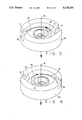
- FIG. 3 is a section along the line A--A of FIG. 2;
- FIG. 4 is a section along line B--B of FIG. 2;
- FIGS. 5 and 6 are axonometric representations of the air and liquid flows through the device in accordance with the invention.
- the device will be explained with regard to a centralized injection unit, but its application is not limited to such a centralized injection unit.
- the invention limited to the atomization of fuel, but any liquid which must be atomized can be used with the present invention.
- the centralized fuel injection device 11 in accordance with FIG. 1 is shown in combination with an injection valve 1 and is fitted directly on the manifold and supplies finely dispersed fuel to the motor.
- a pressure regulator 2 connected to the injection valve through a duct 7 and a throttle valve housing 9 with a throttle valve 10 is shown.
- An intermediate ring 6 is provided between the throttle valve housing 9 and upper housing 8 which positions the injection valve in place.
- the intermediate ring 6 encompasses the atomizing device 11 in accordance with the invention to which there lead two air ducts 30, 31. This device 11 in accordance with the invention is shown in more detail in FIG. 2.
- the injection valve has a valve seat in a known manner on which the valve 1 is opened and closed. Underneath the valve opening 3, that is to say below the valve seat, a housing 12 with an annular disk 13 is arranged upon which is sealed the injection valve 1, whereby the housing 12 has at different levels annular air inlets 4, 5 which are separated from each other by a ridge 21. These air inlets 4, 5 receive compressed air from ducts 30,31.
- a dividing ring 22 aligned radially with the ridge 21 is set in the housing 12 between the annular disc 13 and the bottom of the housing 12. The dividing ring 22 has been elaborated with at least one upper slit 15 connected with the upper air inlet 4 and at least one lower slit 16 connected with the lower air inlet 5. As FIGS.
- each upper slit 15 of the upper level opens tangentially into an upper annular channel 23 and each lower slit 16 of the lower level opens tangentially into a lower annular channel 24.
- the slits 15, 16 taper with reducing radius in a circumferential direction.
- the annular channels 23 and 24 taper with reducing radius in an axial direction to an upper slot 25 and a lower slot 26 respectively, and open into a central cylindrical opening 14 to which the fuel jet is also delivered.
- the slots 25, 26 are likewise annular in shape.
- the upper slit 15, the upper annular channel 23 and the upper slot 25 are limited in an upward direction by the annular disk 13.
- the annular disk 13 has an opening passage 29 which is aligned with the valve opening 3 and is followed in the direction of the flow by the slot 25, the cylindrical opening 14 and the lower slot 26.
- the cylindrical opening 14 extends axially through the dividing ring 22 as far as into the housing 12.
- the fuel jet which enters through valve opening 3 into the cylindrical opening 14 aligned with the latter, is seized at the upper swirl level by the swirl flow (air swirl) emanating from the upper slot 25 and at this point there results the impulse exchange between air and fuel.
- the direction of the air flow through the lower slit 16 at the lower swirl level is opposite to that of the upper swirl level so that at the lower swirl level there results a sense of rotation of the fuel-air swirl opposite to that at the upper swirl level. Due to these opposing directions of rotation of the swirl flows, the rotation of the whole flow downstream from the lower slot 26 is eliminated so that the ejection of the fuel droplets due to centrifugal force from the fuel-air mixture flowing out of the exit opening 28 of the device 11 is avoided.
- the velocity component of the air flow increases in a radial and a tangential direction with the reducing radius of the annular channels 23, 24 and a desired high velocity of the air swirls can thus be achieved.
- FIG. 5 For clarification the upper swirl level is shown in FIG. 5 and the lower swirl level is shown in FIG. 6.
- an air flow 17 is made to enter clockwise through the slit 15 into the annular channel 23, swirls through the upper slot 25 about the fuel jet 19 and then leaves the upper swirl level through the cylindrical opening 14.
- the entry of air takes place through the lower slit 16 and the air flow 18 now swirls about the fuel jet 19 anti-clockwise and leaves the lower swirl level likewise through the cylindrical opening 14. If the swirl flows of the air flows 17 and 18 are of equal magnitude, the rotation of the whole flow downstream of the lower slot 26 is eliminated and a well interspersed fuel-air mixture is delivered to the manifold.
- the ratio of the cross-sectional area of the vertical cylindrical opening 14 to the respective sum of the areas of the slits 15, 16 is chosen to be suitably large, it is ensured that the velocity component in the direction of the longitudinal valve axis remains small. This also ensures that the exit velocity of the fuel droplets from the exit opening 28 is small.
Landscapes
- Engineering & Computer Science (AREA)
- Chemical & Material Sciences (AREA)
- Combustion & Propulsion (AREA)
- Mechanical Engineering (AREA)
- General Engineering & Computer Science (AREA)
- Fuel-Injection Apparatus (AREA)
- Nozzles (AREA)
Abstract
A known device for the atomization of liquids for injection valves including upper and lower fluid entry levels by which a tangential entry of air is provided into a space located below the injection valve in the direction of flow by which the generally occurring unevenness of distribution of fuel to different cylinders of an internal combustion engine is to be improved. The entry of the fluid from the upper and lower levels are oppositely oriented at the individual levels and thus produce two opposing swirl flows. The device is particularly suitable for injection valves for internal combustion engines.
Description
The invention is directed to a device for the atomization of liquids such as for internal engines. The invention is therefore in the sphere of the atomization of liquids by means of compressed air produced independently or by a use of the suction in the manifold of internal combustion engines. The liquids used are particularly fuels to be mixed for combustible mixtures for internal combustion engines with external mixture production. Compressed air or suction in the manifold have up to now been used to atomize fuels in such a manner that the air expanded at an annular slot seizes at high velocity the fuel jet emanating from the opening of the injection valve. The great difference in velocity between the air and fuel leads to atomization.
This type of atomization is however disadvantageous in that fine droplets resulting from the atomization process are accelerated to high velocities in the air flow so that they are in part no longer able to follow a change of direction of the flow of the intake air. The droplets impinge against the wall of the manifold and contribute to the formation of a film on the wall. Only very small tolerances are permissible fir the excentricity of entry of the fuel into the air flow. Excessive manufacturing tolerances in this area lead to deviation sideways of the atomized fuel jet in consequence of which there results in the case of centralized injection an increase in the unevenness of fuel distribution between the individual cylinders of a multi-cylinder engine. A fuel injection device for internal combustion engines is also already known in which the opening of an injection valve is directed into an auxiliary air nozzle whereby the fuel and the air are mixed by swirling in a swirl chamber formed therein. The air entry into the interior space of the auxiliary air nozzle is in this case tangential.
The device for atomization of liquids has an advantage that due to the low exit velocity from the device of the droplets of liquid, these are able to follow the changes of direction of the intake air. The unevenness of distribution of fuel between the individual cylinders of a multi-cylinder internal combustion engine can thereby for instance in the case of centralized injection be effectively reduced particularly in the full power range. The quantity of liquid forming a film on the wall is also reduced, which has a positive effect on the smooth running of internal combustion engines. The atomized jet of liquid emanating from the device has a very good jet symmetry so that there is no unevenness of distribution. In particular no deviation sideways of the liquid jet. This is of particular importance in internal combustion engines.
Advantageous further developments and improvements of the device specified are made possible by measures described hereinafter.
The above advantages are set forth by the use of slits at different levels one above the other in which each open into an annular channel and the annular channels taper with reducing radius and open into a cylindrical opening. In addition it is advantageous if there are several, particularly two, slits in each annular channel. The geometry of the jet of atomized liquid and, in the case of the use of fuel, the distribution of the concentration of the fuel droplets, can be influenced by selecting the number of the tangentially entering slits per swirl level and the geometric position of the slits if the upper or lower swirl level relative to each other. Thereby a further means is obtained to reduce the unevenness of fuel distribution between the individual cylinders by the atomization of the fuel.
The invention is shown in the drawing in the form of an example.
FIG. 1 shows a sectional representation of a centralized injection unit in accordance with the invention as related to a fuel injection valve;
FIG. 2 is a detail of the atomization device shown in of FIG. 1 in accordance with the invention;
FIG. 3 is a section along the line A--A of FIG. 2;
FIG. 4 is a section along line B--B of FIG. 2; and
FIGS. 5 and 6 are axonometric representations of the air and liquid flows through the device in accordance with the invention.
The device will be explained with regard to a centralized injection unit, but its application is not limited to such a centralized injection unit. Nor is the invention limited to the atomization of fuel, but any liquid which must be atomized can be used with the present invention.
The centralized fuel injection device 11 in accordance with FIG. 1 is shown in combination with an injection valve 1 and is fitted directly on the manifold and supplies finely dispersed fuel to the motor. In addition to the injection valve 1, a pressure regulator 2 connected to the injection valve through a duct 7 and a throttle valve housing 9 with a throttle valve 10 is shown.
An intermediate ring 6 is provided between the throttle valve housing 9 and upper housing 8 which positions the injection valve in place. The intermediate ring 6 encompasses the atomizing device 11 in accordance with the invention to which there lead two air ducts 30, 31. This device 11 in accordance with the invention is shown in more detail in FIG. 2.
The injection valve has a valve seat in a known manner on which the valve 1 is opened and closed. Underneath the valve opening 3, that is to say below the valve seat, a housing 12 with an annular disk 13 is arranged upon which is sealed the injection valve 1, whereby the housing 12 has at different levels annular air inlets 4, 5 which are separated from each other by a ridge 21. These air inlets 4, 5 receive compressed air from ducts 30,31. A dividing ring 22 aligned radially with the ridge 21 is set in the housing 12 between the annular disc 13 and the bottom of the housing 12. The dividing ring 22 has been elaborated with at least one upper slit 15 connected with the upper air inlet 4 and at least one lower slit 16 connected with the lower air inlet 5. As FIGS. 3 and 4 also show, in the embodiment shown two upper slits 15 and two lower slits 16 are provided. Each upper slit 15 of the upper level opens tangentially into an upper annular channel 23 and each lower slit 16 of the lower level opens tangentially into a lower annular channel 24. The slits 15, 16 taper with reducing radius in a circumferential direction. The annular channels 23 and 24 taper with reducing radius in an axial direction to an upper slot 25 and a lower slot 26 respectively, and open into a central cylindrical opening 14 to which the fuel jet is also delivered.
The slots 25, 26 are likewise annular in shape. The upper slit 15, the upper annular channel 23 and the upper slot 25 are limited in an upward direction by the annular disk 13. The annular disk 13 has an opening passage 29 which is aligned with the valve opening 3 and is followed in the direction of the flow by the slot 25, the cylindrical opening 14 and the lower slot 26. The cylindrical opening 14 extends axially through the dividing ring 22 as far as into the housing 12. The fuel jet which enters through valve opening 3 into the cylindrical opening 14 aligned with the latter, is seized at the upper swirl level by the swirl flow (air swirl) emanating from the upper slot 25 and at this point there results the impulse exchange between air and fuel. The direction of the air flow through the lower slit 16 at the lower swirl level is opposite to that of the upper swirl level so that at the lower swirl level there results a sense of rotation of the fuel-air swirl opposite to that at the upper swirl level. Due to these opposing directions of rotation of the swirl flows, the rotation of the whole flow downstream from the lower slot 26 is eliminated so that the ejection of the fuel droplets due to centrifugal force from the fuel-air mixture flowing out of the exit opening 28 of the device 11 is avoided.
Because the annular channels 23, 24 taper with reducing radius, the velocity component of the air flow increases in a radial and a tangential direction with the reducing radius of the annular channels 23, 24 and a desired high velocity of the air swirls can thus be achieved.
For clarification the upper swirl level is shown in FIG. 5 and the lower swirl level is shown in FIG. 6. It will be seen in FIG. 5 that an air flow 17 is made to enter clockwise through the slit 15 into the annular channel 23, swirls through the upper slot 25 about the fuel jet 19 and then leaves the upper swirl level through the cylindrical opening 14. At the lower swirl level in accordance with FIG. 6, the entry of air takes place through the lower slit 16 and the air flow 18 now swirls about the fuel jet 19 anti-clockwise and leaves the lower swirl level likewise through the cylindrical opening 14. If the swirl flows of the air flows 17 and 18 are of equal magnitude, the rotation of the whole flow downstream of the lower slot 26 is eliminated and a well interspersed fuel-air mixture is delivered to the manifold.
If the ratio of the cross-sectional area of the vertical cylindrical opening 14 to the respective sum of the areas of the slits 15, 16 is chosen to be suitably large, it is ensured that the velocity component in the direction of the longitudinal valve axis remains small. This also ensures that the exit velocity of the fuel droplets from the exit opening 28 is small.
It remains to be pointed out that it is self-evidently also possible to provide exhaust gas recycling and that air flow 17, 18 can be replaced by an exhaust gas flow.
Claims (5)
1. A device for the atomization of fuel for an internal combustion engine ejected by an injection valve, said device includes a cylindrical passage (14) having a uniform diameter with a fuel inlet opening (29) and a fuel outlet opening (28) coaxial to an axis of the cylindrical passage and upper and lower compressed air swirl passages (17 and 18) situated one above the other axially, each of said upper and lower compressed air swirl passages have a compressed air outlet between said fuel inlet and said fuel outlet openings and in communication with the cylindrical passage and a compressed air inlet, said fuel is ejected through said cylindrical passage from said fuel inlet opening to said fuel outlet opening and said upper and lower swirl passages extend in opposite directions so that a first fluid swirl flow is produced by the upper swirl passages opposite to a second fluid swirl flow produced by the lower swirl passages and the first and second fluid swirl flow passes out through said compressed air outlets to act upon the fuel flow through said cylindrical passage, said upper swirl passage includes at least one upper slit (15) which tapers from an outer larger end to a smaller inner end which opens tangentially into an upper annular channel (23) and said lower swirl passage includes at least one lower slit (16) which tapers from an outer larger end to a smaller inner end which opens into a lower annular channel (24) in such a manner that said second fluid swirl flow (18) is produced in the lower annular channel (24) and swirls in a direction of flow which is in an opposite direction to said first fluid swirl flow (17) produced in the upper annular channel (23).
2. A device for the atomization of fuel for an internal combustion engine ejected by an injection valve, said device includes a cylindrical passage (14) downstream of said injection valve coaxial therewith, an upper annular chamber (23) and a lower annular chamber (24) situated one above the other, at least one upper slit (15) which opens tangentially into said upper annular chamber; said at least one upper slit (15) tapers from a larger outer end to a smaller inner end which connects with said upper annular chamber (23), at least one lower slit (16) which opens tangentially into said lower annular chamber in a direction opposite from that of said at least one upper slit, said at least one lower slit (16) tapers from a larger outer end to a smaller inner end which connects with said lower annular chamber (24), said upper annular chamber (23) includes an annular portion (25) that tapers toward the axis of said cylindrical passage (14) and connects with said cylindrical passage (14), and said lower annular chamber (24) includes an annular portion (26) that tapers toward the axis of said cylindrical passage (14) and connects with said cylindrical passage (14) whereby said at least one upper slit and at least one lower slit (15, 16), said upper and lower annular chambers (23, 24) and said upper and lower tapered annular portions (25, 26) form upper and lower swirl passages in which the swirl in said upper and lower passages are in opposite directions surrounding said cylindrical passage and which act upon a fuel flow through said cylindrical passage (14).
3. A device as set forth in accordance with claim 2, in which the tapered annular portion (25) of said upper swirl passage extends to an upper annular slot that opens into said cylindrical passage (14), and said tapered annular portion (26) of said lower swirl passage extends to a lower annular slot that opens into said cylindrical passage (14).
4. A device for atomization of fuel for an internal combustion engine ejected by an injection valve, said device includes a cylindrical passage (14) downstream of said injection valve coaxial therewith, an upper annular chamber (23) and a lower annular chamber (24) situated one above the other, at least one upper slit (15) which opens tangentially into said upper annular chamber, at least one lower slit (16) which opens tangentially into said lower annular chamber (24) in a direction opposite from that of said at least one upper slit (15), said at least one upper slit tapers from a larger outer end to a smaller inner end which connects with said upper annular chamber 23 said at least one lower slit (16) tapers from a larger outer end to a smaller inner end which connects with said lower annular chamber (24), said upper annular chamber (23) includes an annular portion that tapers toward the axis of said cylindrical passage (14) and connects with said cylindrical passage (14), and said lower annular chamber includes an annular portion that tapers toward the axis of said cylindrical passage (14) and connects with said annular passage (14) whereby said at least one upper and lower slit (15, 16), said upper and lower annular chambers (23, 24), and said upper and lower annular tapered portions of said upper and lower annular chambers form upper and lower swirl passages in which the swirl in said upper and lower swirl passages are in opposite directions surrounding said cylindrical passage and which act upon a fuel flow through said cylindrical passage (14).
5. A device as set forth in accordance with claim 4, in which the annular tapered portion of said upper annular chamber extends to an upper annular slot (25) that opens into said cylindrical passage (14), and said annular tapered portion of said lower annular chamber (24) extends to a lower annular slot (26) that opens into said cylindrical passage (14).
Applications Claiming Priority (2)
| Application Number | Priority Date | Filing Date | Title |
|---|---|---|---|
| DE3921079 | 1989-06-28 | ||
| DE3921079A DE3921079A1 (en) | 1989-06-28 | 1989-06-28 | SPRAYING ARRANGEMENT |
Publications (1)
| Publication Number | Publication Date |
|---|---|
| US5178331A true US5178331A (en) | 1993-01-12 |
Family
ID=6383711
Family Applications (1)
| Application Number | Title | Priority Date | Filing Date |
|---|---|---|---|
| US07/656,094 Expired - Fee Related US5178331A (en) | 1989-06-28 | 1990-05-30 | Device for atomization of fluids |
Country Status (9)
| Country | Link |
|---|---|
| US (1) | US5178331A (en) |
| EP (1) | EP0435973B1 (en) |
| JP (1) | JPH04501450A (en) |
| KR (1) | KR920701666A (en) |
| AU (1) | AU621492B2 (en) |
| BR (1) | BR9006834A (en) |
| DE (2) | DE3921079A1 (en) |
| ES (1) | ES2036115T3 (en) |
| WO (1) | WO1991000426A1 (en) |
Cited By (7)
| Publication number | Priority date | Publication date | Assignee | Title |
|---|---|---|---|---|
| US6089473A (en) * | 1996-09-12 | 2000-07-18 | Robert Bosch Gmbh | Valve, in particular a fuel injection valve |
| US6418925B1 (en) * | 1999-05-20 | 2002-07-16 | Iep Pharmaceutical Devices Inc. | Low spray force, low retention atomization system |
| US20020179740A1 (en) * | 2000-08-23 | 2002-12-05 | Guenter Dantes | Swirl plate and fuel injection valve comprising such a swirl plate |
| US20030234455A1 (en) * | 2002-06-24 | 2003-12-25 | Mieney Harry R. | Non-contacting fuel vaporizer |
| EP1384880A3 (en) * | 2002-07-24 | 2004-12-15 | Delphi Technologies, Inc. | Non-contacting fuel vaporizer |
| EP1392964A4 (en) * | 2001-06-01 | 2006-03-01 | Vaporate Pty Ltd | Fuel delivery system |
| EP4094019A4 (en) * | 2020-01-22 | 2023-07-05 | Turbogen Ltd. | ATOMIZER FOR GAS TURBINE ENGINE |
Families Citing this family (3)
| Publication number | Priority date | Publication date | Assignee | Title |
|---|---|---|---|---|
| US5255658A (en) * | 1990-10-12 | 1993-10-26 | Coltec Industries Inc. | System and apparatus to improve atomization of injected fuel |
| DE9318544U1 (en) * | 1993-12-03 | 1994-01-27 | Rubenberger, Karl, 85435 Erding | Vortex chamber atomizer |
| US5823582A (en) * | 1995-08-24 | 1998-10-20 | Harrow Products, Inc. | Electromagnetically-managed latching exit bar |
Citations (7)
| Publication number | Priority date | Publication date | Assignee | Title |
|---|---|---|---|---|
| US1451063A (en) * | 1923-04-10 | Burner | ||
| US3771728A (en) * | 1971-03-17 | 1973-11-13 | F Polnauer | Spray nozzles with spiral flow of fluid and method of constructing the same |
| US3811278A (en) * | 1973-02-01 | 1974-05-21 | Gen Electric | Fuel injection apparatus |
| GB1366581A (en) * | 1970-11-09 | 1974-09-11 | Delavan Manufacturing Co | Eccentric spiral swirl chamber nozzle |
| US3853273A (en) * | 1973-10-01 | 1974-12-10 | Gen Electric | Axial swirler central injection carburetor |
| US4218012A (en) * | 1977-09-01 | 1980-08-19 | Canadian Patents & Development | Method of rapidly dissolving a particulate substance in a liquid |
| GB2198521A (en) * | 1986-12-10 | 1988-06-15 | Mtu Muenchen Gmbh | Gas turbine fuel injector |
Family Cites Families (5)
| Publication number | Priority date | Publication date | Assignee | Title |
|---|---|---|---|---|
| US2623786A (en) * | 1948-10-01 | 1952-12-30 | Rudolf L Wille | Method for atomizing fuel and nozzle for carrying out this method |
| DE2137030A1 (en) * | 1971-07-23 | 1973-02-01 | Werner Dipl Phys Kraus | FUEL INJECTION DEVICE |
| JPS5510016A (en) * | 1978-07-06 | 1980-01-24 | Nissan Motor Co Ltd | Fuel injection valve |
| JPS57183559A (en) * | 1981-05-06 | 1982-11-11 | Hitachi Ltd | Fuel injection valve |
| JPS58195058A (en) * | 1982-05-07 | 1983-11-14 | Toyota Motor Corp | Air assist device for fuel injection internal-combustion engine |
-
1989
- 1989-06-28 DE DE3921079A patent/DE3921079A1/en not_active Withdrawn
-
1990
- 1990-05-30 WO PCT/DE1990/000402 patent/WO1991000426A1/en not_active Ceased
- 1990-05-30 ES ES199090908460T patent/ES2036115T3/en not_active Expired - Lifetime
- 1990-05-30 EP EP90908460A patent/EP0435973B1/en not_active Expired - Lifetime
- 1990-05-30 BR BR909006834A patent/BR9006834A/en not_active IP Right Cessation
- 1990-05-30 US US07/656,094 patent/US5178331A/en not_active Expired - Fee Related
- 1990-05-30 AU AU56697/90A patent/AU621492B2/en not_active Ceased
- 1990-05-30 JP JP2507899A patent/JPH04501450A/en active Pending
- 1990-05-30 DE DE9090908460T patent/DE59000361D1/en not_active Expired - Lifetime
- 1990-05-30 KR KR1019910700217A patent/KR920701666A/en not_active Withdrawn
Patent Citations (7)
| Publication number | Priority date | Publication date | Assignee | Title |
|---|---|---|---|---|
| US1451063A (en) * | 1923-04-10 | Burner | ||
| GB1366581A (en) * | 1970-11-09 | 1974-09-11 | Delavan Manufacturing Co | Eccentric spiral swirl chamber nozzle |
| US3771728A (en) * | 1971-03-17 | 1973-11-13 | F Polnauer | Spray nozzles with spiral flow of fluid and method of constructing the same |
| US3811278A (en) * | 1973-02-01 | 1974-05-21 | Gen Electric | Fuel injection apparatus |
| US3853273A (en) * | 1973-10-01 | 1974-12-10 | Gen Electric | Axial swirler central injection carburetor |
| US4218012A (en) * | 1977-09-01 | 1980-08-19 | Canadian Patents & Development | Method of rapidly dissolving a particulate substance in a liquid |
| GB2198521A (en) * | 1986-12-10 | 1988-06-15 | Mtu Muenchen Gmbh | Gas turbine fuel injector |
Cited By (8)
| Publication number | Priority date | Publication date | Assignee | Title |
|---|---|---|---|---|
| US6089473A (en) * | 1996-09-12 | 2000-07-18 | Robert Bosch Gmbh | Valve, in particular a fuel injection valve |
| US6418925B1 (en) * | 1999-05-20 | 2002-07-16 | Iep Pharmaceutical Devices Inc. | Low spray force, low retention atomization system |
| US20020179740A1 (en) * | 2000-08-23 | 2002-12-05 | Guenter Dantes | Swirl plate and fuel injection valve comprising such a swirl plate |
| US6764033B2 (en) * | 2000-08-23 | 2004-07-20 | Robert Bosch Gmbh | Swirl plate and fuel injection valve comprising such a swirl plate |
| EP1392964A4 (en) * | 2001-06-01 | 2006-03-01 | Vaporate Pty Ltd | Fuel delivery system |
| US20030234455A1 (en) * | 2002-06-24 | 2003-12-25 | Mieney Harry R. | Non-contacting fuel vaporizer |
| EP1384880A3 (en) * | 2002-07-24 | 2004-12-15 | Delphi Technologies, Inc. | Non-contacting fuel vaporizer |
| EP4094019A4 (en) * | 2020-01-22 | 2023-07-05 | Turbogen Ltd. | ATOMIZER FOR GAS TURBINE ENGINE |
Also Published As
| Publication number | Publication date |
|---|---|
| KR920701666A (en) | 1992-08-12 |
| JPH04501450A (en) | 1992-03-12 |
| ES2036115T3 (en) | 1993-05-01 |
| AU5669790A (en) | 1991-01-17 |
| EP0435973A1 (en) | 1991-07-10 |
| BR9006834A (en) | 1991-08-06 |
| DE59000361D1 (en) | 1992-11-19 |
| WO1991000426A1 (en) | 1991-01-10 |
| AU621492B2 (en) | 1992-03-12 |
| EP0435973B1 (en) | 1992-10-14 |
| DE3921079A1 (en) | 1991-01-03 |
Similar Documents
| Publication | Publication Date | Title |
|---|---|---|
| US4945877A (en) | Fuel injection valve | |
| US4301657A (en) | Gas turbine combustion chamber | |
| US4629127A (en) | Intermittent swirl type injection valve | |
| US5570841A (en) | Multiple disk swirl atomizer for fuel injector | |
| US4347823A (en) | Throttle body injection apparatus with distribution skirt | |
| US8033114B2 (en) | Multimode fuel injector for combustion chambers, in particular of a jet engine | |
| US2595759A (en) | Atomizing nozzle for spraying viscous liquids | |
| US5360166A (en) | Fuel injection valve | |
| US3414242A (en) | Device for balanced homogenization of air and liquid fuel mixtures in internal combustion engines | |
| US4107918A (en) | Combustion assembly | |
| US3904119A (en) | Air-fuel spray nozzle | |
| US5178331A (en) | Device for atomization of fluids | |
| US4655395A (en) | Adjustable conical atomizer | |
| US5059357A (en) | Vortex chamber atomizer | |
| US4159881A (en) | Turbulent flow conveying device for a mixture | |
| JPH04265468A (en) | Device for injecting fuel-gas-mixture | |
| US5012981A (en) | Injection valve | |
| US4235210A (en) | Fuel supply apparatus for internal combustion engines | |
| US4365753A (en) | Boundary layer prefilmer airblast nozzle | |
| JPH0637977B2 (en) | Fuel injection device for turbojet engine | |
| US4673536A (en) | Fuel admixture device | |
| US4354470A (en) | Fuel supply apparatus in internal combustion engine | |
| US3977374A (en) | Arrangement for the preparation of the fuel-air mixture for an internal combustion engine | |
| US4407128A (en) | Fuel burners | |
| US4285320A (en) | Variable capacity fuel delivery system for engines |
Legal Events
| Date | Code | Title | Description |
|---|---|---|---|
| AS | Assignment |
Owner name: ROBERT BOSCH GMBH Free format text: ASSIGNMENT OF ASSIGNORS INTEREST.;ASSIGNOR:SCHUERZ, WILLIBALD;REEL/FRAME:005812/0486 Effective date: 19910201 |
|
| FEPP | Fee payment procedure |
Free format text: PAYOR NUMBER ASSIGNED (ORIGINAL EVENT CODE: ASPN); ENTITY STATUS OF PATENT OWNER: LARGE ENTITY |
|
| REMI | Maintenance fee reminder mailed | ||
| LAPS | Lapse for failure to pay maintenance fees | ||
| FP | Lapsed due to failure to pay maintenance fee |
Effective date: 19970115 |
|
| STCH | Information on status: patent discontinuation |
Free format text: PATENT EXPIRED DUE TO NONPAYMENT OF MAINTENANCE FEES UNDER 37 CFR 1.362 |