US517543A - davis - Google Patents
davis Download PDFInfo
- Publication number
- US517543A US517543A US517543DA US517543A US 517543 A US517543 A US 517543A US 517543D A US517543D A US 517543DA US 517543 A US517543 A US 517543A
- Authority
- US
- United States
- Prior art keywords
- frame
- truck
- frames
- piano
- shafts
- Prior art date
- Legal status (The legal status is an assumption and is not a legal conclusion. Google has not performed a legal analysis and makes no representation as to the accuracy of the status listed.)
- Expired - Lifetime
Links
- 238000012856 packing Methods 0.000 description 4
- 238000004804 winding Methods 0.000 description 2
- 230000001174 ascending effect Effects 0.000 description 1
- 230000003028 elevating effect Effects 0.000 description 1
- 230000010006 flight Effects 0.000 description 1
- 230000005484 gravity Effects 0.000 description 1
- 230000033001 locomotion Effects 0.000 description 1
- 238000000034 method Methods 0.000 description 1
- 230000000284 resting effect Effects 0.000 description 1
Images
Classifications
-
- B—PERFORMING OPERATIONS; TRANSPORTING
- B66—HOISTING; LIFTING; HAULING
- B66F—HOISTING, LIFTING, HAULING OR PUSHING, NOT OTHERWISE PROVIDED FOR, e.g. DEVICES WHICH APPLY A LIFTING OR PUSHING FORCE DIRECTLY TO THE SURFACE OF A LOAD
- B66F3/00—Devices, e.g. jacks, adapted for uninterrupted lifting of loads
Definitions
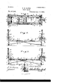
- Figure 1 is atop or plan view of atruck embodying my said invention, drawn out or lengthened somewhat from its shortest position; Fig. 2 aside elevation of the same; Fig. 3 a longitudinal section thereof, as seen from the dottedline 3 3 in Fig. 1"; Fig. 3 a detail sectional view as seen from the dotted line a: m in Fig. 2; Fig. 4 an end elevation" on a somewhat enlarged scale; Fig. 5 a detail sectional view as seen from the dotted line 5 5 in Fig. 4; Fig. 6 a detail sectional view as seen from the dotted line 6 6 in Fig. 5; Fig.
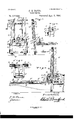
- FIG. 7 a transverse sectional view as seen from the dotted line 7 7m Fig. 2, with the frame J in its lower position, and Fig.8 a side elevation similar to a portion of Fig. 2,but showing, by means of dotted lines, various positions of the truck.
- portions marked A and B represent the two portions of the structure which constitute the bottom or supporting frame-work of the truck; 0 and D the two end frames; E and F braces connecting the frames A C and B D, respectively; G and H windlasses upon the frames 0 and D; I an arm mounted upon the frame A, and extending out through the frame 0, for purposes which will be presently described, and J a frame carrying a roller, and attached to the other end of the frame A.
- the frame portions A and B each consist of a stout crosshead and two legs, the legs of which are each divided into two members and extend toward and past each other, the members of one pass ing between the members of the other, with rods R R passing through them, whereby a firm although slidable attachment between themissecured.
- ThisisbestillustratedinFig. 1 where the two frame parts arevshown as drawn out a short distance from their shortest or most closed-up position.
- These'frame parts are provided with arms A and B which extend'out and engage with the ends of the shafts O and D whereby the raising and lowering is accomplished, as will be presently more fully described.
- Upon the frames A B are clamps P between which to secure the piano.
- the cross-heads of the frame parts are recessed or cut away on the upper sides, from a point flush with the faces of these clamps to the inner sides of said cross-heads, as shown'in Fig. 3, and the resulting recesses a, I) receive the rear casters of the piano, and permit the piano to sit flat upon the frame, instead of resting upon its casters.
- the front casters overhang one edge of the frame of the truck.
- the frame In placing a piano upon a truck, the frame is lowered to the floor, the piano tipped,and the frame drawn partially under it, and the piano is tipped back and shoved on until its rear side is about three fourths across the frame, which brings the center of gravity about to the centerof the truck, the front ends of the foot pieces of the piano with the casters thereon projecting over the side of the truck frame.
- the truck frame is then drawn tightly together until'the clamps P come against the ends-of the piano, when the rodRis screwed up tightly by means of its hand nut r, whichflsecures the truck frame in its adjusted position.
- This closing together may be effected by attaching a rope to some part of one end of the truck frame, say to the arm I, and bringing it back and taking a turn around the shaft D, when, by turning said shaft with the crank, the frame is slid together.
- a spool i may be upon the shaft D to receive this rope.
- the rope in doing this, runs over the sheave s in the end of the frame B.
- the end frames 0 and D are rectangular frames mounted upon casters 0 and d, and provided with long slots in which shafts O Y and D are mounted, which shafts are capable of being raised or lowered in said slots from ICO one end to the other, thus carrying the frame A B, to which they are attached, from the floor to a considerable elevation.
- the brace bars E and F are connected to the lower ends of the end frames 0 and D and with the inner ends of the frame partsA and B, respectively, and serve to secure said frame parts in their relative position when assembled and arranged for use, as shown in the drawings.
- the rods E connect the frames 0 A, and the rods F the frames D B.
- the lower ends of said braces are detached from the pins efon the frames 0 D, said frames will swing over on the pivots formed by the shafts O and D, and lay flat on top the frame parts A B,-the clamps P at the same time being permitted to fold down by means of their hinges p, and the slots in said frames C and D permitting said frames to slide endwise, so that the casters thereon project but little beyond the ends of the arms A B on the frame parts A B.
- the ends of said braces E l which have been detached from the pins e fare preferably, in packing the device, placed upon the ends of the shafts O and D, which are permitted to project for this purpose.
- Windlass shafts Gand II are mounted in bearings in the upper portions of the frames (3 and D, respectively, and serve as spools upon which to wind the ends of the ropes G and I1. Said ropes are attached to the upper ends of the frames 0 and D, and pass thence down around sheaves 0' cl on the shafts G D, and thence up to these Windlass shafts G and If.
- the sheaves c d are loosely mounted on their shafts, and run easily thereon, at the same time multiplying the power, the same as in an ordinary Windlass.
- these shafts C D are guards C D which incase the sheaves c d, and prevent the ropes from falling off, away from said sheaves, when said ropes are loose, as they would otherwise do.
- the frame A B is raised to the desired elevation.
- Ratchets and pawls g g are provided by which the elevation attained may be secured. By disengaging the pawls from the ratchets, the frame is, of course, permitted to descend, and may rest directly upon the floor,-the slots in the frames 0 D being long enough for this purpose.
- the arm I is secured by means of a bolt 1 to the frame A, and extends out, centrally, through the frame 0 to a little distance beyond it, and to this outer end is attached a housing I in which is a roller or rollers 1
- the rollers I are preferably of considerable length, so as to give substantially the bearing surface of a pair of double casters. I have shown two, but obviously one of the proper length would answer substantially the same purpose, except it is desirable to have two to turn independently in certain contingencies, which will hereinafter be described.
- the housing I is secured to the arm I by a bolt 2', and preferably also by a pin i which prevents it from swinging.
- the main office of this arm and its roller or rollers is illustrated in Fig.
- the rope G is then loosened, letting the weight rest upon the rollers 1
- the frame 0 is then raised (which may be easily done by hand) to the same level, when the truck is moved forward, on the rollers 1 ,to the point shown by the second set of dotted lines, and then by winding up the rope G, the weight is taken off the rollers 1 which, as the frame A B is raised, are carried to the level of the next step, when the operation may be repeated.
- the frame J is placed between the legs of the parts A B of the main frame, and is provided with a roller J.
- This frame and its roller are of service in passing obstructions in the surface over which the piano is being moved, as carpet strips and the like.
- the mode of operation is, when such an obstruction is reached, to let this rollerdown in contact with thevfioor, where it is held by its brace bar J which has notches, as shown in Fig. 3, which engage with a transverse rod j.
- the rope 11 maybe loosened, and the end frame D raised sufficiently to pass over the obstruction, after which said frame D can be lowered, and again brought into service, and the frame J with its roller J relieved from service.
- a similar movement can be effected at the otherend of the truck when the braces F would begin to interfere with it further progress.
- a piano may be carried up a long flight of steps, by laying ordinary running boards on said steps, with a pulley at the top and a rope running from the truck to said pulley, in the same manner, generally speaking, as is usually employed in drawing heavy weights up flights of stairs.
- the rope in such a case would be attached at one end to some part of the frame of the truck, pass thence under one of the rollers I in the groove therein (shown in Fig. 4), thence through the pulley at the top of the stairs, back under the other roller 1 (in the groove therein) thence over the sheave s in the other end of the frame B (in the groove therein) to the spool d on the shaft D.
- the shaft D being revolved by means of the crank K, the piano and truck are drawn, together, up the flight of stairs, as will be readily understood.
- a single person in this way can elevate a heavy piano from a lower to an upper story.
Landscapes
- Life Sciences & Earth Sciences (AREA)
- Engineering & Computer Science (AREA)
- Geology (AREA)
- Mechanical Engineering (AREA)
- Structural Engineering (AREA)
- Handcart (AREA)
Description
' 2 Sheets-Sheet 1. F.- E. DAVIS.
PIANO TRUCK.
"(N0 Model.)
I Paten-ted'Apr. 3, 1894. T r 1' .B E
INVENTOR Fra n-k ELDa vi 3,
THE NATIONAL umusmpnms COMPANY WASHINGTON. n. c.
' 2 Sheets-Sl1eet 2. P. B. DAVIS.
(No Model.)
PIANO TRUCK.
Patented Apr. 3, 1894.
INVENTOI? Fran]: EfiDavz's,
WITNESSES.-
UNITED STATES PATENT OFFIc FRANK E. DAVIS, OF COLUMBUS, ASSIGNOR OF ONE-HALF TO JOHN B. MCCOY, OF INDIANAPOLIS, INDIANA.
' PlANO-TRUbK.
SPECIFICATION forming part of Letters Patent No. 517,543, dated April 3, 1894. Application filed December 27, 1893- Serial No. 94,835. (No model.)
' To all whom it may concern.-
be first fully described and the novel features thereof then pointed out in the claims.
Referring to the accompanying drawings, which are made a part hereof, and on which similar letters of reference indicate similar parts, Figure 1 is atop or plan view of atruck embodying my said invention, drawn out or lengthened somewhat from its shortest position; Fig. 2 aside elevation of the same; Fig. 3 a longitudinal section thereof, as seen from the dottedline 3 3 in Fig. 1"; Fig. 3 a detail sectional view as seen from the dotted line a: m in Fig. 2; Fig. 4 an end elevation" on a somewhat enlarged scale; Fig. 5 a detail sectional view as seen from the dotted line 5 5 in Fig. 4; Fig. 6 a detail sectional view as seen from the dotted line 6 6 in Fig. 5; Fig. 7 a transverse sectional view as seen from the dotted line 7 7m Fig. 2, with the frame J in its lower position, and Fig.8 a side elevation similar to a portion of Fig. 2,but showing, by means of dotted lines, various positions of the truck. A,
In said drawings the portions marked A and B represent the two portions of the structure which constitute the bottom or supporting frame-work of the truck; 0 and D the two end frames; E and F braces connecting the frames A C and B D, respectively; G and H windlasses upon the frames 0 and D; I an arm mounted upon the frame A, and extending out through the frame 0, for purposes which will be presently described, and J a frame carrying a roller, and attached to the other end of the frame A. The frame portions A and B each consist of a stout crosshead and two legs, the legs of which are each divided into two members and extend toward and past each other, the members of one pass ing between the members of the other, with rods R R passing through them, whereby a firm although slidable attachment between themissecured. ThisisbestillustratedinFig. 1, where the two frame parts arevshown as drawn out a short distance from their shortest or most closed-up position. These'frame parts are provided with arms A and B which extend'out and engage with the ends of the shafts O and D whereby the raising and lowering is accomplished, as will be presently more fully described. Upon the frames A B are clamps P between which to secure the piano. The cross-heads of the frame parts are recessed or cut away on the upper sides, from a point flush with the faces of these clamps to the inner sides of said cross-heads, as shown'in Fig. 3, and the resulting recesses a, I) receive the rear casters of the piano, and permit the piano to sit flat upon the frame, instead of resting upon its casters. The front casters overhang one edge of the frame of the truck. In placing a piano upon a truck, the frame is lowered to the floor, the piano tipped,and the frame drawn partially under it, and the piano is tipped back and shoved on until its rear side is about three fourths across the frame, which brings the center of gravity about to the centerof the truck, the front ends of the foot pieces of the piano with the casters thereon projecting over the side of the truck frame. The truck frame is then drawn tightly together until'the clamps P come against the ends-of the piano, when the rodRis screwed up tightly by means of its hand nut r, whichflsecures the truck frame in its adjusted position. This closing together may be effected by attaching a rope to some part of one end of the truck frame, say to the arm I, and bringing it back and taking a turn around the shaft D, when, by turning said shaft with the crank, the frame is slid together. A spool (i may be upon the shaft D to receive this rope. The rope, in doing this, runs over the sheave s in the end of the frame B. When it is desired to spreadthe frame, it can easily be done by loosening the nut r on the rod R, when the frame can be slipped endwise, by hand, without difficulty.
The end frames 0 and D are rectangular frames mounted upon casters 0 and d, and provided with long slots in which shafts O Y and D are mounted, which shafts are capable of being raised or lowered in said slots from ICO one end to the other, thus carrying the frame A B, to which they are attached, from the floor to a considerable elevation. The brace bars E and F are connected to the lower ends of the end frames 0 and D and with the inner ends of the frame partsA and B, respectively, and serve to secure said frame parts in their relative position when assembled and arranged for use, as shown in the drawings. The rods E connect the frames 0 A, and the rods F the frames D B. Slots through the frames A B permit the transverse rods R and R, to which these braces are respectively united, to slide back and forth,the rod R sliding in slots in the frame B, and the rod R, sliding in slots in the frame A. These braces are made detachable at one or both ends for the purpose of enabling the truck to be reduced to convenient condition for packing or transportation. \Vhen, for instance, the lower ends of said braces are detached from the pins efon the frames 0 D, said frames will swing over on the pivots formed by the shafts O and D, and lay flat on top the frame parts A B,-the clamps P at the same time being permitted to fold down by means of their hinges p, and the slots in said frames C and D permitting said frames to slide endwise, so that the casters thereon project but little beyond the ends of the arms A B on the frame parts A B. The ends of said braces E l which have been detached from the pins e fare preferably, in packing the device, placed upon the ends of the shafts O and D, which are permitted to project for this purpose.
The Windlass shafts Gand II are mounted in bearings in the upper portions of the frames (3 and D, respectively, and serve as spools upon which to wind the ends of the ropes G and I1. Said ropes are attached to the upper ends of the frames 0 and D, and pass thence down around sheaves 0' cl on the shafts G D, and thence up to these Windlass shafts G and If. The sheaves c d are loosely mounted on their shafts, and run easily thereon, at the same time multiplying the power, the same as in an ordinary Windlass. I-Iungupon these shafts C D are guards C D which incase the sheaves c d, and prevent the ropes from falling off, away from said sheaves, when said ropes are loose, as they would otherwise do. As will be readily understood, by winding up the Windlass shafts G and H, which maybe done by means of a crank K, the frame A B is raised to the desired elevation. Ratchets and pawls g g are provided by which the elevation attained may be secured. By disengaging the pawls from the ratchets, the frame is, of course, permitted to descend, and may rest directly upon the floor,-the slots in the frames 0 D being long enough for this purpose.
Racks and pinions are equivalents for the ropes and sheaves, and may of course be substituted therefor without departing from my invention.
The arm I is secured by means of a bolt 1 to the frame A, and extends out, centrally, through the frame 0 to a little distance beyond it, and to this outer end is attached a housing I in which is a roller or rollers 1 The rollers I are preferably of considerable length, so as to give substantially the bearing surface of a pair of double casters. I have shown two, but obviously one of the proper length would answer substantially the same purpose, except it is desirable to have two to turn independently in certain contingencies, which will hereinafter be described. The housing I is secured to the arm I by a bolt 2', and preferably also by a pin i which prevents it from swinging. The main office of this arm and its roller or rollers is illustrated in Fig. 8, where is shown the method of using this truck in raising a piano up a short flight of steps, (or into a dray or wagom) that position being shown in full lines where the weight of the whole structure is caused to rest on the step by means of this arm, housing and its rollers;-with the end frame 0 raised to position ready to be moved onto the step, which position is also shown by dotted lines. In accomplishing this work, the whole truck, with the piano, is rolled up to in front of the steps to be mounted, when it is in the position shown by the lower dotted lines,-the arm I extending out over the step. The rope G is then loosened, letting the weight rest upon the rollers 1 The frame 0 is then raised (which may be easily done by hand) to the same level, when the truck is moved forward, on the rollers 1 ,to the point shown by the second set of dotted lines, and then by winding up the rope G, the weight is taken off the rollers 1 which, as the frame A B is raised, are carried to the level of the next step, when the operation may be repeated.
In reducing this structure to condition for packing or transportation, the pin 2' is removed, the housing I straightened out in line with the arm I, and the whole swung around on the bolt 1' to a position over the frame A B;-the frame 0 having previously been folded down on its pivots formed by the shaft 0.
The frame J is placed between the legs of the parts A B of the main frame, and is provided with a roller J. This frame and its roller are of service in passing obstructions in the surface over which the piano is being moved, as carpet strips and the like. The mode of operation is, when such an obstruction is reached, to let this rollerdown in contact with thevfioor, where it is held by its brace bar J which has notches, as shown in Fig. 3, which engage with a transverse rod j. Whenthcse parts are in position to sustain the weight, the rope 11 maybe loosened, and the end frame D raised sufficiently to pass over the obstruction, after which said frame D can be lowered, and again brought into service, and the frame J with its roller J relieved from service. A similar movement can be effected at the otherend of the truck when the braces F would begin to interfere with it further progress.-
A piano may be carried up a long flight of steps, by laying ordinary running boards on said steps, with a pulley at the top and a rope running from the truck to said pulley, in the same manner, generally speaking, as is usually employed in drawing heavy weights up flights of stairs. The rope in such a case would be attached at one end to some part of the frame of the truck, pass thence under one of the rollers I in the groove therein (shown in Fig. 4), thence through the pulley at the top of the stairs, back under the other roller 1 (in the groove therein) thence over the sheave s in the other end of the frame B (in the groove therein) to the spool d on the shaft D. The shaft D being revolved by means of the crank K, the piano and truck are drawn, together, up the flight of stairs, as will be readily understood. A single person in this way can elevate a heavy piano from a lower to an upper story.
Having thus fully described my said invention, what I claim as new, and desire to secure by Letters Patent, is-
1. The combination, in a piano truck, of two frame parts A B the legs of which are membered and pass between each other, said legs being also slotted in the other direction, with bolts R R passing through the slots of the members of one set of frame legs and attached to the ends of the members of the other set of frame legs, whereby an extensible truck body or bottom is sec.ured,substantially as set forth.
2. The combination,in apiano truck, of the truck body or bottom, the end frames,-slots or guides in said end frames, shafts secured in said slots or guides, connections between the body or bottom and said shafts, and gearing mounted upon said end frames, whereby said shafts may be driven up and down the same and the truck body or bottom thus elevated and lowered, substantially as set forth. 1
3. The combination, in a piano truck, of the truck body or bottom, the slotted end frames G D, shafts in the slots, connections between the body or bottom and said shafts, Windlasses in the upper ends of said frames 0 D, and ropes connecting said windlasses and said shafts, whereby they may be elevated, together with the truck body or bottom, substantially as set forth.
4. The combination, in a piano truck, of the body or bottom, arms thereon, shafts connected to said arms, slotted end frames, the slots whereof pass over said shafts, and detachable braces E F connected to the body or bottom andto the end frames, whereby the frames may be secured in position for use, or permitted to be folded down for packing or transportation, substantially as shown and described.
5. The combination, in a piano truck, with the body or bottom adapted to be elevated relatively to the end frames by which it is supported, said end frames, an arm Isecured, to said body or bottom andextending out and provided with a roller, said parts being arranged and operating as specified, whereby the truck may be utilized in ascending or descending from one level to another, substantially as set forth.
6. The combination, in a piano truck, of the body or bottom, end frames supporting the same, means of raising and lowering the body or bottom relatively to said end frames, a cen-. tral frame J having a roller J and means for adjusting and holding said frame and roller, substantially as and for the purposes set forth.
7. The combination, in a piano truck, of the body or bottom, the end frames, the shafts O and D, the windlasses Gand H, ropes G and H, sheaves c and d on said shafts, and inclosing guards or casings G and D surrounding said sheaves,substantially as set forth.
8. The combination, in a piano truck, of the body or bottom, end frames to which said body or bottom is connected, and mechanism for elevating and lowering said'bottom upon said end frames, said bottom being provided 100 with recesses a b to receive the rear trucks of the piano when placed thereon, substantially as shown and described.
9. The combination, in a piano truck, of the body frame composed ofthe two frame parts A and B, the two end frames 0 and D provided with slots, shafts mounted in said slots, connections extending from said frames A and B to said shafts, gearing mounted. on said end frames and adapted to drive said shafts, no together with the bottom frame, up and down, an arm I extendingout from the frameA and bearing rollers, a frame J secured to the other end of the frameA and bearing a roller, and braces E and F connecting the frames A I I5 Oand B D, respectively, the whole being constructed, arranged and operating substantially as set forth. 7
In witness whereof I have hereunto set my hand and seal, at Indianapolis, Indiana, this 16th day of December, A. D. 1893.
ERANK' E. DAVIS. [14. s.]
Witnesses:
CHESTER BRADFORD, J OHN B. MoGoY.
Publications (1)
| Publication Number | Publication Date |
|---|---|
| US517543A true US517543A (en) | 1894-04-03 |
Family
ID=2586346
Family Applications (1)
| Application Number | Title | Priority Date | Filing Date |
|---|---|---|---|
| US517543D Expired - Lifetime US517543A (en) | davis |
Country Status (1)
| Country | Link |
|---|---|
| US (1) | US517543A (en) |
Cited By (1)
| Publication number | Priority date | Publication date | Assignee | Title |
|---|---|---|---|---|
| US2577257A (en) * | 1945-12-15 | 1951-12-04 | William R Cochrane | Crib |
-
0
- US US517543D patent/US517543A/en not_active Expired - Lifetime
Cited By (1)
| Publication number | Priority date | Publication date | Assignee | Title |
|---|---|---|---|---|
| US2577257A (en) * | 1945-12-15 | 1951-12-04 | William R Cochrane | Crib |
Similar Documents
| Publication | Publication Date | Title |
|---|---|---|
| US4258826A (en) | Combination stepladder and load lifting apparatus | |
| US2035294A (en) | Portable hoisting machine | |
| US1676449A (en) | Hoisting machine | |
| US897462A (en) | Portable stacking-elevator. | |
| US227401A (en) | Fire-escape | |
| US517543A (en) | davis | |
| US2621777A (en) | Portable elevator support | |
| US732367A (en) | Truck. | |
| US815416A (en) | Elevating-truck. | |
| US1290267A (en) | Transportable adjustable automobile-rack. | |
| US1409906A (en) | Portable elevator | |
| US489628A (en) | colleret | |
| US219691A (en) | Improvement in traveling cranes | |
| US1408522A (en) | Hoisting apparatus | |
| US552180A (en) | Extension-ladder and fire-escape | |
| US1721020A (en) | Portable elevator | |
| US541683A (en) | Elevator | |
| US533597A (en) | Combined water-tower and fire-escape | |
| US701975A (en) | Derrick. | |
| US502484A (en) | Extension fire-ladder | |
| US283654A (en) | Fiee escape laddee | |
| US1128626A (en) | Wagon-hoist. | |
| US278891A (en) | Straw-stacker | |
| US653618A (en) | Steam log-loader. | |
| US573630A (en) | Thirds to william a |