US516438A - Faucet - Google Patents
Faucet Download PDFInfo
- Publication number
- US516438A US516438A US516438DA US516438A US 516438 A US516438 A US 516438A US 516438D A US516438D A US 516438DA US 516438 A US516438 A US 516438A
- Authority
- US
- United States
- Prior art keywords
- faucet
- plunger
- handle
- tube
- rack plate
- Prior art date
- Legal status (The legal status is an assumption and is not a legal conclusion. Google has not performed a legal analysis and makes no representation as to the accuracy of the status listed.)
- Expired - Lifetime
Links
- 238000010276 construction Methods 0.000 description 6
- 210000004907 Glands Anatomy 0.000 description 2
- 235000013405 beer Nutrition 0.000 description 2
- 238000005266 casting Methods 0.000 description 2
- 239000012530 fluid Substances 0.000 description 2
Images

Classifications
-
- F—MECHANICAL ENGINEERING; LIGHTING; HEATING; WEAPONS; BLASTING
- F16—ENGINEERING ELEMENTS AND UNITS; GENERAL MEASURES FOR PRODUCING AND MAINTAINING EFFECTIVE FUNCTIONING OF MACHINES OR INSTALLATIONS; THERMAL INSULATION IN GENERAL
- F16K—VALVES; TAPS; COCKS; ACTUATING-FLOATS; DEVICES FOR VENTING OR AERATING
- F16K1/00—Lift valves or globe valves, i.e. cut-off apparatus with closure members having at least a component of their opening and closing motion perpendicular to the closing faces
- F16K1/30—Lift valves or globe valves, i.e. cut-off apparatus with closure members having at least a component of their opening and closing motion perpendicular to the closing faces specially adapted for pressure containers
- F16K1/304—Shut-off valves with additional means
- F16K1/305—Shut-off valves with additional means with valve member and actuator on the same side of the seat
-
- Y—GENERAL TAGGING OF NEW TECHNOLOGICAL DEVELOPMENTS; GENERAL TAGGING OF CROSS-SECTIONAL TECHNOLOGIES SPANNING OVER SEVERAL SECTIONS OF THE IPC; TECHNICAL SUBJECTS COVERED BY FORMER USPC CROSS-REFERENCE ART COLLECTIONS [XRACs] AND DIGESTS
- Y10—TECHNICAL SUBJECTS COVERED BY FORMER USPC
- Y10T—TECHNICAL SUBJECTS COVERED BY FORMER US CLASSIFICATION
- Y10T137/00—Fluid handling
- Y10T137/8593—Systems
- Y10T137/87917—Flow path with serial valves and/or closures
Definitions
- This invention relates to the class of cock faucets, and particularly to a beer faucet, and its novelty will be fully understood from the following description and claims when taken in connection with the annexed drawings: and the novelty of the invention is to provide a faucet of simple, durable and inexpensive construction.
- a further object of the invention is to provide means for opening and closinga faucet, which can be operated without the least lost motion or uncertainty of the operation ofthe parts of the faucet, either in opening or closing the same.
- a still further object of the invention is to provide a cutoff, or means in the tube between the barrel and faucet whereby the valve or plunger of the faucet may be removed and replaced without detaching itfrom the barrel or keg to which it is secured.
- the invention consists in the novel construction and arrangement of the several parts of the faucet and cut off as will be hereinafter more fully described and set upin the claims.
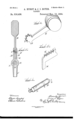
- Figure l is a side elevation.
- Fig. 2 is a longitudinal sectional view.
- Fig. 3 is a perspective view of the handle and its toothed sector.
- Fig. 4 is a perspective view of the sliding rack plate.
- Fig. 5 is a vertical section taken on the plane indicated by the dotted line X-X in Fig. 2.
- Fig. 6 is a perspective view of the plunger and its attachments.
- the tube or stem A which is of ordinary Y' construction', is provided upon the outside near the faucet, with an inner screw threaded projection a, and opposite this projection ct, is formed in the wall of the tube or stem A, a valve seat B. Fitted in the said projection a, is a screw valve b, which is operated to cut off, or close the stem or tube when the faucet is being repaired.
- the mouth C Projecting downwardly from the tube A, cast or formed in the same piece, and of course directly communicating with it, is the mouth C, of the faucet.
- The' faucet end of the tube A is enlarged from just in front of4 the projection a, to its extreme end, forming 6c the valve seat c, at the juncture of the said enlarged and small portions of the' tube or y stem A, Cast or otherwise formed upon the said enlarged portion opposite the mouth C, are two Iianges D, between which the handle E, is fulcrumed by means of the screw bolt e.
- the lower or fulcrumed portion of the handle E has formed in the same piece with it, the toothed sector F, through which sector the fulcrum bolt e, passes.
- a V shaped lug or projection d which forms a stop when it strikes the rack plate G, and prevents the handle from being pushed too far back.
- the rack plate G .slides upon the said enlarged end .of the tube A, between the flanges D, is engaged by the sector F, and slides back and forth according to the movement of the han dle E.
- valve seat made in the wall of the said stem, and the screw valve operated through the said projection, combined with the operating handle, the plunger, the rack plate having an arm depending through the plunger, the toothed sector forming one end of the oper ating handle fulcrumed to the said anges, and the V shaped lug formed at the juncture of the handle and sector to stop the outward movement of the said rack plate and plunger, substantially as shown and described.
Description
(No Model.) ZISheets-Sheet 1.
A. BURST 8v J. I. BOYER.
FAUGBT.
(No Model.) 2 Shets-Sheet 2.
A. BURST & JL IQBOYER. FAUGBT.
No. 516,438. Patented Mar. 13, 1894.
5ft/unaniem witwassen UNITED STATES PATENT. ma,
ALEXANDER HURST AND JESSE" I. BOYER, OF READING, PENNSYLVANIA.
FAUCET.
SPECIFICATION forming part of Letters Patent No. 516,438, dated March 13, 1894.
Application filed September 5, I893. Serial No. 484,812. (No model.)
To all whom it may concern:
Be it known thatl we, ALEXANDER HURsr and JESSE I. BOYER, citizens of the United States, residing at Reading, in the county of Berks and State of Pennsylvania, have invented certain new and useful Improvements in Faucets, of which the following is a speci- Iication.
This invention relates to the class of cock faucets, and particularly to a beer faucet, and its novelty will be fully understood from the following description and claims when taken in connection with the annexed drawings: and the novelty of the invention is to provide a faucet of simple, durable and inexpensive construction.
A further object of the invention is to provide means for opening and closinga faucet, which can be operated without the least lost motion or uncertainty of the operation ofthe parts of the faucet, either in opening or closing the same.
A still further object of the invention, is to provide a cutoff, or means in the tube between the barrel and faucet whereby the valve or plunger of the faucet may be removed and replaced without detaching itfrom the barrel or keg to which it is secured.
The invention consists in the novel construction and arrangement of the several parts of the faucet and cut off as will be hereinafter more fully described and set upin the claims.
In the accompanying drawings forming part of this application: Figure lis a side elevation. Fig. 2 is a longitudinal sectional view. Fig. 3 is a perspective view of the handle and its toothed sector. Fig. 4 is a perspective view of the sliding rack plate. Fig. 5 is a vertical section taken on the plane indicated by the dotted line X-X in Fig. 2. Fig. 6 is a perspective view of the plunger and its attachments.
The same letters of reference denote the same parts throughout the several figures of the drawings.
The tube or stem A, which is of ordinary Y' construction', is provided upon the outside near the faucet, with an inner screw threaded projection a, and opposite this projection ct, is formed in the wall of the tube or stem A, a valve seat B. Fitted in the said projection a, isa screw valve b, which is operated to cut off, or close the stem or tube when the faucet is being repaired.
Projecting downwardly from the tube A, cast or formed in the same piece, and of course directly communicating with it, is the mouth C, of the faucet. The' faucet end of the tube A, is enlarged from just in front of4 the projection a, to its extreme end, forming 6c the valve seat c, at the juncture of the said enlarged and small portions of the' tube or y stem A, Cast or otherwise formed upon the said enlarged portion opposite the mouth C, are two Iianges D, between which the handle E, is fulcrumed by means of the screw bolt e. The lower or fulcrumed portion of the handle E, has formed in the same piece with it, the toothed sector F, through which sector the fulcrum bolt e, passes. At the juncture 7o of the rear lower portion ofthe handle and the said sector, is formed a V shaped lug or projection d, which forms a stop when it strikes the rack plate G, and prevents the handle from being pushed too far back. The rack plate G,.slides upon the said enlarged end .of the tube A, between the flanges D, is engaged by the sector F, and slides back and forth according to the movement of the han dle E. .At the outer end of the rack plate G, 8o at right angles thereto and in the same piece, is formed an arm H, which projects downwardly through the outer end of the plunger I, the said outer end of the plunger being provided with ahand knob or handle h, to opcrate the plunger should the handle E, orits engaged parts become broken. The inner endl of the plunger is made smaller, and is provided with a sleeve or packing gland K, to secure the packing lain position, while the 9o packingor gasket L, which forms the valve, is secured to the said sleeve, and the sleeve to the plunger, by means of the screw Z. It is obvious from the foregoing description, that as the plate G, is moved back and forth, 95. it will carry with it the plunger, and thus open and close the fluid channel.
We do not Wish to be understood as limiting ourselves to the particular arrangement of the parts of our device, nor to forming or 10o casting them in the same piece, but desireto reserve to ourselves the right to change the location and manner of forming them without departing from the spirit of our invention.
Having thus described our invention, what we claim as new, `and desire to secure by Letters Patent, is
l. The combination with the faucet having oppositely situated flanges, of the handle termnatingin atoothed sectorfulcrumed to and between the flanges, the V shaped stop lug formed at the juncture of the sector and handle, the rack plate slidably located between the said flanges but not secured to them, the depending arm formed at right angles to the rack plate and extending through the plunger, and the plunger having an operating handle formed upon its outer end, substantially as shown and described.
2. In a faucet having fianges opposite the faucets mouth, the inner screw threaded projection formed integral with the faucet stem,
the valve seat made in the wall of the said stem, and the screw valve operated through the said projection, combined with the operating handle, the plunger, the rack plate having an arm depending through the plunger, the toothed sector forming one end of the oper ating handle fulcrumed to the said anges, and the V shaped lug formed at the juncture of the handle and sector to stop the outward movement of the said rack plate and plunger, substantially as shown and described.
In Witness whereof We hereunto set our hands in the presence of two Witnesses.
, ALEXANDER HURST.
JESSE l. BOYER.V Titnessesz EUGENE RHEIN, WALTER B. CRAIG.
Publications (1)
| Publication Number | Publication Date |
|---|---|
| US516438A true US516438A (en) | 1894-03-13 |
Family
ID=2585243
Family Applications (1)
| Application Number | Title | Priority Date | Filing Date |
|---|---|---|---|
| US516438D Expired - Lifetime US516438A (en) | Faucet |
Country Status (1)
| Country | Link |
|---|---|
| US (1) | US516438A (en) |
Cited By (5)
| Publication number | Priority date | Publication date | Assignee | Title |
|---|---|---|---|---|
| US2512320A (en) * | 1946-02-05 | 1950-06-20 | Frederick C Fischer | Valve |
| US3324483A (en) * | 1964-11-13 | 1967-06-13 | Daniel P Conroy | Portable sink |
| US6457614B1 (en) | 2001-12-13 | 2002-10-01 | Vent-Matic Co., Inc. | Dispensing faucet for a pressurized source |
| US20070194264A1 (en) * | 2006-02-21 | 2007-08-23 | Gennady Arov | Faucet with floating seal member |
| US20080089170A1 (en) * | 2006-10-16 | 2008-04-17 | Hamilton Beach/Proctor-Silex, Inc. | Mixing device configured to blend food |
-
0
- US US516438D patent/US516438A/en not_active Expired - Lifetime
Cited By (8)
| Publication number | Priority date | Publication date | Assignee | Title |
|---|---|---|---|---|
| US2512320A (en) * | 1946-02-05 | 1950-06-20 | Frederick C Fischer | Valve |
| US3324483A (en) * | 1964-11-13 | 1967-06-13 | Daniel P Conroy | Portable sink |
| US6457614B1 (en) | 2001-12-13 | 2002-10-01 | Vent-Matic Co., Inc. | Dispensing faucet for a pressurized source |
| US20070194264A1 (en) * | 2006-02-21 | 2007-08-23 | Gennady Arov | Faucet with floating seal member |
| US8066257B2 (en) | 2006-02-21 | 2011-11-29 | Gennady Arov | Faucet with floating seal member |
| US20080089170A1 (en) * | 2006-10-16 | 2008-04-17 | Hamilton Beach/Proctor-Silex, Inc. | Mixing device configured to blend food |
| US20080089171A1 (en) * | 2006-10-16 | 2008-04-17 | Hamilton Beach/Proctor-Silex, Inc. | Mixing Device Configured to Blend Food |
| US7871195B2 (en) | 2006-10-16 | 2011-01-18 | Hamilton Beach Brands, Inc. | Mixing device configured to blend food |
Similar Documents
| Publication | Publication Date | Title |
|---|---|---|
| US516438A (en) | Faucet | |
| US932172A (en) | Water cock or faucet. | |
| US247668A (en) | Half to james lawrence english | |
| US180891A (en) | Improvement in faucets | |
| US1003179A (en) | Faucet. | |
| US607732A (en) | burger | |
| US1148193A (en) | Faucet. | |
| US900984A (en) | Faucet. | |
| US418774A (en) | Ernst wagner | |
| US588779A (en) | Henry reinach | |
| US537545A (en) | Spigot | |
| US711846A (en) | Self-closing faucet. | |
| US147693A (en) | Improvement in gage-cocks for steasvi-bojlers | |
| US507456A (en) | Cock or faucet | |
| US465766A (en) | roberts | |
| US537773A (en) | harris | |
| US495711A (en) | Hydrant | |
| US330377A (en) | Hydrant | |
| US201634A (en) | Eight to geobge | |
| US480512A (en) | Valve mechanism for steam-radiators | |
| US758100A (en) | Handle for pneumatic tools. | |
| US756624A (en) | Shut-off valve. | |
| US142051A (en) | Improvement in self-venting bungs | |
| US144097A (en) | Improvement in faucets | |
| US167821A (en) | Improvement in vent-faucets |