US201634A - Eight to geobge - Google Patents
Eight to geobge Download PDFInfo
- Publication number
- US201634A US201634A US201634DA US201634A US 201634 A US201634 A US 201634A US 201634D A US201634D A US 201634DA US 201634 A US201634 A US 201634A
- Authority
- US
- United States
- Prior art keywords
- handle
- valve
- lever
- nozzle
- faucet
- Prior art date
- Legal status (The legal status is an assumption and is not a legal conclusion. Google has not performed a legal analysis and makes no representation as to the accuracy of the status listed.)
- Expired - Lifetime
Links
- 239000007788 liquid Substances 0.000 description 6
- 238000012856 packing Methods 0.000 description 6
- 229910001369 Brass Inorganic materials 0.000 description 3
- 239000010951 brass Substances 0.000 description 3
- PXHVJJICTQNCMI-UHFFFAOYSA-N Nickel Chemical compound [Ni] PXHVJJICTQNCMI-UHFFFAOYSA-N 0.000 description 2
- 238000010276 construction Methods 0.000 description 2
- 229910001018 Cast iron Inorganic materials 0.000 description 1
- CWYNVVGOOAEACU-UHFFFAOYSA-N Fe2+ Chemical compound [Fe+2] CWYNVVGOOAEACU-UHFFFAOYSA-N 0.000 description 1
- 229910000754 Wrought iron Inorganic materials 0.000 description 1
- HCHKCACWOHOZIP-UHFFFAOYSA-N Zinc Chemical compound [Zn] HCHKCACWOHOZIP-UHFFFAOYSA-N 0.000 description 1
- 235000013405 beer Nutrition 0.000 description 1
- JEIPFZHSYJVQDO-UHFFFAOYSA-N iron(III) oxide Inorganic materials O=[Fe]O[Fe]=O JEIPFZHSYJVQDO-UHFFFAOYSA-N 0.000 description 1
- 229910052759 nickel Inorganic materials 0.000 description 1
- 230000007096 poisonous effect Effects 0.000 description 1
- 239000011701 zinc Substances 0.000 description 1
- 229910052725 zinc Inorganic materials 0.000 description 1
Images

Classifications
-
- F—MECHANICAL ENGINEERING; LIGHTING; HEATING; WEAPONS; BLASTING
- F16—ENGINEERING ELEMENTS AND UNITS; GENERAL MEASURES FOR PRODUCING AND MAINTAINING EFFECTIVE FUNCTIONING OF MACHINES OR INSTALLATIONS; THERMAL INSULATION IN GENERAL
- F16K—VALVES; TAPS; COCKS; ACTUATING-FLOATS; DEVICES FOR VENTING OR AERATING
- F16K1/00—Lift valves or globe valves, i.e. cut-off apparatus with closure members having at least a component of their opening and closing motion perpendicular to the closing faces
Definitions
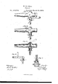
- Figure l is a side elevation of the faucet with the lever-handle in the position when the valve is closed.
- Fig. 2 is a side elevation of the faucet with the lever-handle in the position when the valve isl open for continuous draft.
- Fig. 3 is a longitudinal section of the faucet.
- Fig. 4 is a detail view of the lever-handle, loop, and nozzle.
- Fig. 5 is a detail view of the detachable valve-seat, valve, and spring.
- My invention relates to that class of faucets known as self-closing compression-faucets;77 and consists in details of construction hereinafter fully described, and it is more particularly designed for beer and ale kegs, and isto be used to draw liquids either direct from the nozzle or from the terminus of a continuous pipe.
- A Fig. 1
- A Fig. 1
- B double-faced valvecasing, made of brass. The upper face is screwed intoV the shell A.
- a is a projection or stop for the wroughtirbn lever-handle C to rest against when a continuous draft is desired.
- cis aloop also made of wroughtiron, and pivoted to the handle, and which passes over the butt-end of and rests upon the shell A, to hold the nozzle and lever-handle in place when not in operation; but when a continuous iiow is required, the loop c, to be out of the way, can be placed in position as shown in dotted lines, Fig. 4.
- b are lugson the valvecasing for the bent ends of the lever-handle to slip over, and which alsoform the fulcrum for the leverage, and also afford means for unscrewing the valve casin g; D, the nozzle, made of brass, with collar d2.
- the lever-handle and the nozzle are connected together at the nozzle-collar d by side bars h, with riveted pivots; d, a rubber packing, which en circles the tubular projection d1 of the nozzle, and which is pressed against the lower face of the valve-casing B, to prevent leakage when the faucet is being used.
- c is a circular valve, with luted guide el and thin rubber packing e2, with a projection, e3, on the top to keep the spiral spring fin place. This spiral spring is to press down and keep closed the valve e when not in use.
- the notches g in the lever-handle are designed to be used as a wrench when it is necessary to remove the valve-casing B from the shell A for the purpose of replacing the thin rubber packing e2 on valve e.
- the operation for drawing liquids is very simple, and is as follows: When it is desired to draw direct from the cask or barrel, and to insure any desired flow, it is only necessary to raise the lever-handle C in proportion to the iiow required fromthe horizontal position, as shown in Fig. 1. This operation raises the nozzle, which presses the rubber packing d against the under face of the valve-casing B. At the same time the tubular projection cl forces up ward valve c, and compresses the spring f, thereby allowing the ow of liquid through the shell A down through the liuted guide c1 to the outlet of the nozzle.- When the handle is released the spring forces back the valve to its seat, thereby preventing any escape of liquid.
Landscapes
- Engineering & Computer Science (AREA)
- General Engineering & Computer Science (AREA)
- Mechanical Engineering (AREA)
- Multiple-Way Valves (AREA)
Description
W. D. SEAL.
Faucet.
arch 26.1878..
' M Zargftented @W5 MWL N. PETERS, PNOTO-LITMOGRAPHR, WASHXNGON. D4 C.
UNITED 3 l WILLIAM D. SEAL, on WASHINGTON, DIsrRIOT orV COLUMBIA', Assienon or ONE-HALF nrs` RIGHT' rcencuen' w. HARvEY, j on j PLAGE.
Specification forming part of 'Letters ,Batent No. 20l`,63`4`,`dated'Mareh 26; 1,878 applicationiil'ed March 5, 187e.
To all whom it may concern:
Be it known that I, WILLIAu D. SEAL, of Washington, in the District of Columbia, have invented a new and valuable Improvement in Faucets; and I do hereby declare that the following is a full, clear, and exact description of the construction and operation of the same, reference being had to the annexed drawing, making a part of this specification, and to the letters and figures of reference marked thereon.
Figure l is a side elevation of the faucet with the lever-handle in the position when the valve is closed. Fig. 2 is a side elevation of the faucet with the lever-handle in the position when the valve isl open for continuous draft. Fig. 3 is a longitudinal section of the faucet. Fig. 4 is a detail view of the lever-handle, loop, and nozzle. Fig. 5 is a detail view of the detachable valve-seat, valve, and spring.
My invention relates to that class of faucets known as self-closing compression-faucets;77 and consists in details of construction hereinafter fully described, and it is more particularly designed for beer and ale kegs, and isto be used to draw liquids either direct from the nozzle or from the terminus of a continuous pipe.
On reference to the drawing, A, Fig. 1, is the shell of the faucet, with but one continuous unbroken opening, made of cast-iron to insure strength and cheapness, and also to avoid the poisonous effects caused by the liquids remaining in the brass shells uowin common use. It is coated or galvanized with nickel or zinc to prevent rust. B, double-faced valvecasing, made of brass. The upper face is screwed intoV the shell A. a is a projection or stop for the wroughtirbn lever-handle C to rest against when a continuous draft is desired. (See Fig. 2.) cis aloop, also made of wroughtiron, and pivoted to the handle, and which passes over the butt-end of and rests upon the shell A, to hold the nozzle and lever-handle in place when not in operation; but when a continuous iiow is required, the loop c, to be out of the way, can be placed in position as shown in dotted lines, Fig. 4. b are lugson the valvecasing for the bent ends of the lever-handle to slip over, and which alsoform the fulcrum for the leverage, and also afford means for unscrewing the valve casin g; D, the nozzle, made of brass, with collar d2. The lever-handle and the nozzle are connected together at the nozzle-collar d by side bars h, with riveted pivots; d, a rubber packing, which en circles the tubular projection d1 of the nozzle, and which is pressed against the lower face of the valve-casing B, to prevent leakage when the faucet is being used. c is a circular valve, with luted guide el and thin rubber packing e2, with a projection, e3, on the top to keep the spiral spring fin place. This spiral spring is to press down and keep closed the valve e when not in use.
The notches g in the lever-handle are designed to be used as a wrench when it is necessary to remove the valve-casing B from the shell A for the purpose of replacing the thin rubber packing e2 on valve e.
The operation for drawing liquids is very simple, and is as follows: When it is desired to draw direct from the cask or barrel, and to insure any desired flow, it is only necessary to raise the lever-handle C in proportion to the iiow required fromthe horizontal position, as shown in Fig. 1. This operation raises the nozzle, which presses the rubber packing d against the under face of the valve-casing B. At the same time the tubular projection cl forces up ward valve c, and compresses the spring f, thereby allowing the ow of liquid through the shell A down through the liuted guide c1 to the outlet of the nozzle.- When the handle is released the spring forces back the valve to its seat, thereby preventing any escape of liquid. To have a continuous liow of liquid, raise the lever-handle C so that it will pass a vertical position and remain against the stop or projection a, as shown in Fig. 2; and when the faucet is designed solely to draw from the terminus of a continuous pipe, one end of the said pipe is securedV in any desired manner to the nozzle D, the lever-handle remainingv in the position as shown in Fig. 2, and the loop c may be dispensed with. When it is desired to lock the faucet, detach the combination of the lever-handle, loop, and nozzle, as shown at Fig. 4.
The advantage claimed in a shell with but one continuous unbroken opening is, that it y vlessens the liability to leakage, as there is but guide c1, thin rubber packing e2, circular valve e, projection e3, and spiral spring f, all arranged.
and operating substantially as set forth.
3. The lever-handle C, loop c, notches g, pivoted side bars h, in combination with the nozzle D, nozzle-collar d2, rubber packing d,
and tubular projection d1, arranged and operating substantially as described.
In testimony whereof I have hereunto subscribed my name.
. WM. D. SEAL.
Witnesses:
Jos. S. STETTINIUS, H. C. SIssoN.
Publications (1)
| Publication Number | Publication Date |
|---|---|
| US201634A true US201634A (en) | 1878-03-26 |
Family
ID=2271039
Family Applications (1)
| Application Number | Title | Priority Date | Filing Date |
|---|---|---|---|
| US201634D Expired - Lifetime US201634A (en) | Eight to geobge |
Country Status (1)
| Country | Link |
|---|---|
| US (1) | US201634A (en) |
Cited By (2)
| Publication number | Priority date | Publication date | Assignee | Title |
|---|---|---|---|---|
| US2776849A (en) * | 1954-12-23 | 1957-01-08 | Charles G Homuth | Semi-automatic dispensing valve |
| US3174519A (en) * | 1962-02-20 | 1965-03-23 | Precision Valve Corp | Method of and apparatus for filling gas cigar and cigarette lighters |
-
0
- US US201634D patent/US201634A/en not_active Expired - Lifetime
Cited By (2)
| Publication number | Priority date | Publication date | Assignee | Title |
|---|---|---|---|---|
| US2776849A (en) * | 1954-12-23 | 1957-01-08 | Charles G Homuth | Semi-automatic dispensing valve |
| US3174519A (en) * | 1962-02-20 | 1965-03-23 | Precision Valve Corp | Method of and apparatus for filling gas cigar and cigarette lighters |
Similar Documents
| Publication | Publication Date | Title |
|---|---|---|
| US729145A (en) | Beer-keg tap. | |
| US201634A (en) | Eight to geobge | |
| US1003179A (en) | Faucet. | |
| US666383A (en) | Self-closing cock for water or other fluids. | |
| US111877A (en) | Improvement in fire-extinguishers | |
| US305084A (en) | James lawson | |
| US777265A (en) | Faucet. | |
| US1148193A (en) | Faucet. | |
| US144097A (en) | Improvement in faucets | |
| US283021A (en) | Faucet and racking-valve | |
| US577924A (en) | Gate-valve | |
| US564242A (en) | Jacob henry burlich | |
| US387455A (en) | Siphon | |
| US579114A (en) | Gate-valve | |
| US961011A (en) | Faucet. | |
| US214531A (en) | Improvement in faucets | |
| US36473A (en) | Improvement in faucets | |
| US123926A (en) | Improvement in siphon-cans for carbureters | |
| US311080A (en) | James d | |
| US201887A (en) | Improvement-in barrel-filling devices | |
| US162888A (en) | Improvement in air-pump faucets | |
| US142051A (en) | Improvement in self-venting bungs | |
| US734355A (en) | Faucet. | |
| US219079A (en) | Improvement in faucets | |
| US839543A (en) | Dispensing apparatus. |