US51592A - Improvement in boring wells - Google Patents
Improvement in boring wells Download PDFInfo
- Publication number
- US51592A US51592A US51592DA US51592A US 51592 A US51592 A US 51592A US 51592D A US51592D A US 51592DA US 51592 A US51592 A US 51592A
- Authority
- US
- United States
- Prior art keywords
- windlass
- rope
- derrick
- standard
- pulley
- Prior art date
- Legal status (The legal status is an assumption and is not a legal conclusion. Google has not performed a legal analysis and makes no representation as to the accuracy of the status listed.)
- Expired - Lifetime
Links
- 239000002965 rope Substances 0.000 description 34
- XEEYBQQBJWHFJM-UHFFFAOYSA-N iron Chemical compound [Fe] XEEYBQQBJWHFJM-UHFFFAOYSA-N 0.000 description 4
- 206010010254 Concussion Diseases 0.000 description 2
- 238000005452 bending Methods 0.000 description 2
- 230000000994 depressed Effects 0.000 description 2
- 229910052742 iron Inorganic materials 0.000 description 2
- 238000002360 preparation method Methods 0.000 description 2
Images
Classifications
-
- E—FIXED CONSTRUCTIONS
- E01—CONSTRUCTION OF ROADS, RAILWAYS, OR BRIDGES
- E01C—CONSTRUCTION OF, OR SURFACES FOR, ROADS, SPORTS GROUNDS, OR THE LIKE; MACHINES OR AUXILIARY TOOLS FOR CONSTRUCTION OR REPAIR
- E01C23/00—Auxiliary devices or arrangements for constructing, repairing, reconditioning, or taking-up road or like surfaces
- E01C23/06—Devices or arrangements for working the finished surface; Devices for repairing or reconditioning the surface of damaged paving; Recycling in place or on the road
- E01C23/09—Devices or arrangements for working the finished surface; Devices for repairing or reconditioning the surface of damaged paving; Recycling in place or on the road for forming cuts, grooves, or recesses, e.g. for making joints or channels for markings, for cutting-out sections to be removed; for cleaning, treating, or filling cuts, grooves, recesses, or fissures; for trimming paving edges
- E01C23/0906—Devices or arrangements for working the finished surface; Devices for repairing or reconditioning the surface of damaged paving; Recycling in place or on the road for forming cuts, grooves, or recesses, e.g. for making joints or channels for markings, for cutting-out sections to be removed; for cleaning, treating, or filling cuts, grooves, recesses, or fissures; for trimming paving edges for forming, opening-out, cleaning, drying or heating cuts, grooves, recesses or, excluding forming, cracks, e.g. cleaning by sand-blasting or air-jet ; for trimming paving edges
- E01C23/0926—Devices or arrangements for working the finished surface; Devices for repairing or reconditioning the surface of damaged paving; Recycling in place or on the road for forming cuts, grooves, or recesses, e.g. for making joints or channels for markings, for cutting-out sections to be removed; for cleaning, treating, or filling cuts, grooves, recesses, or fissures; for trimming paving edges for forming, opening-out, cleaning, drying or heating cuts, grooves, recesses or, excluding forming, cracks, e.g. cleaning by sand-blasting or air-jet ; for trimming paving edges with power-driven tools, e.g. vibrated, percussive cutters
Definitions
- the object of this invention is to improve some of the devices and appliances used in connection with a derrick for boring oil and other deep wells; and it consists in applying a brake to the windlass on which the drill-rope is wound, so as to control the descent of the drill when it is to be lowered in preparation for work; also, in placing a pulley in front of the windlass of the said pump-rope, so that the rope shall be wound thereon square, although the windlass may not be directly in front of the derrick also, in a mode of making the frame which sustains the windlass of the sand-pump rope.
- A designates a derriclr, made in any suitable manner and designed to support the windlass, pulleys, and other appliances required in boring a deep well.
- the drill is here seen suspended from a rope which passes over a pulley in the top of the derrick and is thence conducted to a windlass, B, whose axle has its bearings in posts secured to the derrick.
- lVly invention provides a remedy for this state of things by attaching a metallic band, C, to one of the posts that support the windf lass B in such a way as that itshall nearly envelop the axle of the windlass at one end thereof, which end is, moreover, bound around with iron to prevent the burning of the axle when the friction-band is brought close around it.
- the upper end of the metallic band is attached to a lever, D, which has its fulcrum in said windlass-post, and when the lever is depressed the metallic band is brought against the axle, so as to act as a brake and retard its motion.
- Another feature of my invention relates to the control of the sand-pump rope.
- L is the sand-pump, suspended from a rope which passes over a pulley xed in the top of the derrick.
- the windlass which holds this rope is placed at one side of the middle of the derrick, out of line with the well, for
- F designates the windlass of the sand-pump rope.
- the standard PI in which one end of its axle is supported, is so connected to its platform or bed-as to be capable ot motion at right angles to the axis of the windlass, so that it can bring the friction-pulley o up against or away from the periphery of the driving-wheel m, thereby causing the rope to be wound on or off the windlass as is required by the work.
- a rope, J extends from the top of the standard H to an upright lever, K, pivoted to the door of the derrick near the bore of the Well, so that the attendant can,without moving from his place, bring the pulley o up against the driving-pulley and wind up the rope of the sand-pump by merely drawing the lever K toward the left.
- the lever I may be operated by hand or it may be continually drawn toward the right by a weight or spring.
- the standard P which supports the outer end ofthe windlass F, is mostly concealed by the cap G.
- This cap is connected to the standard H by a mortise-and-tenon joint, and to the standard P by a pivot-hin ge, so that it can have motion about the standard P as about a center When the standard H is moved forward or backward.
- the cap serves to connect the standards H and P and tends to prevent the shaft from becoming loose and out of order in its bearings.
- the rope n is conducted from the windlass F to a pulley, 1, running in a block, Q, that is fastened to the derrick.
- the position ot' this pulley is directly opposite the middle of the wiudlass F, so that the rope is continually in a direction at right angles, or nearly so, with the windlass. Hitherto the rope has been conducted from the windlass F directly up to pulleys in the top of the derrick, causing the rope to extend in an oblique direction, whereby it was wound in a heap at one end of the windlass.
Description
@Nimaia STATES ArnNr OFFICE.,
P. J. HYNES, OF GOOPERSTOWN, PENNSYLVANIA Specication forming part of Letters Patent No. 5 5,592, dated December 19, 186.3.
To all whom it may concern:
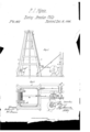
Be it known that I, P. J. HYNES, of Cooperstown, in the county of Venango and State of Pennsylvania, have invented a new and useful Improvement in Apparatus for Boring Wells; and I do hereby declare that the following is a full, clear, and exact description thereof, which will enable others skilled in the art to make and use the same, reference being had to the accompanying drawings, forming part of the specification, in which- Figure 1 is a side elevation of a derrick for supporting and operating tools and devices used in boring oil and other deep wells. Fig. 2 is a plan View, part of which is a horizontal section taken in the line a' of Fig. 1.
Similar letters of reference indicate like parts.
The object of this invention is to improve some of the devices and appliances used in connection with a derrick for boring oil and other deep wells; and it consists in applying a brake to the windlass on which the drill-rope is wound, so as to control the descent of the drill when it is to be lowered in preparation for work; also, in placing a pulley in front of the windlass of the said pump-rope, so that the rope shall be wound thereon square, although the windlass may not be directly in front of the derrick also, in a mode of making the frame which sustains the windlass of the sand-pump rope.
A designates a derriclr, made in any suitable manner and designed to support the windlass, pulleys, and other appliances required in boring a deep well. The drill is here seen suspended from a rope which passes over a pulley in the top of the derrick and is thence conducted to a windlass, B, whose axle has its bearings in posts secured to the derrick.
In letting the drill, which usually is very heavy, into a well it is necessary to retard its descent when it approaches the bottom of the bore, to prevent bending or fracture ot' the parts. This retardation is usually accomplished at present by means of a rop'e applied on the outside of the axle or of one of the flanges of the windlass and fastened to one of the girths of the derrick. This plan is objectionable, because the rope sometimes gets burned and becomes broken, letting the drill or other tool fall in the well from a great height,
causing them to become so bent by the violent concussion that theycannot be taken out again, and the consequence is that the well must be abandoned. n
lVly invention provides a remedy for this state of things by attaching a metallic band, C, to one of the posts that support the windf lass B in such a way as that itshall nearly envelop the axle of the windlass at one end thereof, which end is, moreover, bound around with iron to prevent the burning of the axle when the friction-band is brought close around it. The upper end of the metallic band is attached to a lever, D, which has its fulcrum in said windlass-post, and when the lever is depressed the metallic band is brought against the axle, so as to act as a brake and retard its motion. By this means the attendant can always control the rapidity of descent of the tools into a well.
Another feature of my invention relates to the control of the sand-pump rope.
L is the sand-pump, suspended from a rope which passes over a pulley xed in the top of the derrick. The windlass which holds this rope is placed at one side of the middle of the derrick, out of line with the well, for
convenience in arranging and disposing some.
of the machinery (not here shown) connected with the operation of boring a well, and for other purposes, as seen in Fig. 2.
F designates the windlass of the sand-pump rope. The standard PI, in which one end of its axle is supported, is so connected to its platform or bed-as to be capable ot motion at right angles to the axis of the windlass, so that it can bring the friction-pulley o up against or away from the periphery of the driving-wheel m, thereby causing the rope to be wound on or off the windlass as is required by the work.
A rope, J, extends from the top of the standard H to an upright lever, K, pivoted to the door of the derrick near the bore of the Well, so that the attendant can,without moving from his place, bring the pulley o up against the driving-pulley and wind up the rope of the sand-pump by merely drawing the lever K toward the left.
The standard His drawn back so as to carry the pulley o away from the wheel m by means of a lever, I, which is connected to the upper part of the standard by a cord or Wire.
The lever I may be operated by hand or it may be continually drawn toward the right by a weight or spring.
The standard P, which supports the outer end ofthe windlass F, is mostly concealed by the cap G. This cap is connected to the standard H by a mortise-and-tenon joint, and to the standard P by a pivot-hin ge, so that it can have motion about the standard P as about a center When the standard H is moved forward or backward. The cap serves to connect the standards H and P and tends to prevent the shaft from becoming loose and out of order in its bearings.
The rope n is conducted from the windlass F to a pulley, 1, running in a block, Q, that is fastened to the derrick. The position ot' this pulley is directly opposite the middle of the wiudlass F, so that the rope is continually in a direction at right angles, or nearly so, with the windlass. Hitherto the rope has been conducted from the windlass F directly up to pulleys in the top of the derrick, causing the rope to extend in an oblique direction, whereby it was wound in a heap at one end of the windlass.
I claim as new and desire to secure by Letters Patenty Connecting the cap G of the frame of the sand-pump Windlass to the rigid standard P by a pivot, and to the loose standard H by a fixed joint, substantially as and for the purpose above described.
P. J. HYNES. Witnesses:
J. P. BYERs, J. W. BYERs.
Publications (1)
| Publication Number | Publication Date |
|---|---|
| US51592A true US51592A (en) | 1865-12-19 |
Family
ID=2121141
Family Applications (1)
| Application Number | Title | Priority Date | Filing Date |
|---|---|---|---|
| US51592D Expired - Lifetime US51592A (en) | Improvement in boring wells |
Country Status (1)
| Country | Link |
|---|---|
| US (1) | US51592A (en) |
Cited By (2)
| Publication number | Priority date | Publication date | Assignee | Title |
|---|---|---|---|---|
| US2869239A (en) * | 1955-02-24 | 1959-01-20 | Spand And Jurs Co | Tank gauging apparatus |
| US20180310271A1 (en) * | 2015-01-13 | 2018-10-25 | Fujitsu Limited | Wireless communications system, control station, and terminal |
-
0
- US US51592D patent/US51592A/en not_active Expired - Lifetime
Cited By (2)
| Publication number | Priority date | Publication date | Assignee | Title |
|---|---|---|---|---|
| US2869239A (en) * | 1955-02-24 | 1959-01-20 | Spand And Jurs Co | Tank gauging apparatus |
| US20180310271A1 (en) * | 2015-01-13 | 2018-10-25 | Fujitsu Limited | Wireless communications system, control station, and terminal |
Similar Documents
| Publication | Publication Date | Title |
|---|---|---|
| US700678A (en) | Drilling-machine. | |
| US51592A (en) | Improvement in boring wells | |
| US2675996A (en) | Shaft drill rig | |
| US9404318B2 (en) | Top drive counter moment system | |
| US286837A (en) | lindell | |
| US412525A (en) | And ebenezer | |
| US441540A (en) | Machine | |
| US48006A (en) | Improvement in drills for boring wells | |
| US865548A (en) | Apparatus for boring cylinders. | |
| US842656A (en) | Support for pneumatic tools. | |
| US53992A (en) | Improved drill and crane attachment | |
| US491164A (en) | Means for handling drill-bits for oil or artesian wells | |
| US1527931A (en) | Drill-bit sling | |
| US682287A (en) | Well-drilling machine. | |
| US495852A (en) | Oil-well-drilling apparatus | |
| US98625A (en) | Improvement in tongs for lifting and adjusting well-tubing | |
| US1053189A (en) | Spring drilling apparatus. | |
| US428461A (en) | Rig for drilling wells | |
| US146182A (en) | Improvement in windlasses and cranks for brakes | |
| US692645A (en) | Apparatus for boring wells by percussion. | |
| US166468A (en) | Improvement in windlasses | |
| US2079841A (en) | Rotary rig drilling control | |
| US51189A (en) | Improved drilling-machine | |
| US54656A (en) | Improved method of boring oil-wells | |
| US244819A (en) | Hiram k |