US5127875A - Suction device for the exhaust gases of motor vehicles - Google Patents
Suction device for the exhaust gases of motor vehicles Download PDFInfo
- Publication number
- US5127875A US5127875A US07/616,364 US61636490A US5127875A US 5127875 A US5127875 A US 5127875A US 61636490 A US61636490 A US 61636490A US 5127875 A US5127875 A US 5127875A
- Authority
- US
- United States
- Prior art keywords
- suction
- trolleys
- trolley
- rail
- section
- Prior art date
- Legal status (The legal status is an assumption and is not a legal conclusion. Google has not performed a legal analysis and makes no representation as to the accuracy of the status listed.)
- Expired - Fee Related
Links
Images


Classifications
-
- B—PERFORMING OPERATIONS; TRANSPORTING
- B08—CLEANING
- B08B—CLEANING IN GENERAL; PREVENTION OF FOULING IN GENERAL
- B08B15/00—Preventing escape of dirt or fumes from the area where they are produced; Collecting or removing dirt or fumes from that area
- B08B15/002—Preventing escape of dirt or fumes from the area where they are produced; Collecting or removing dirt or fumes from that area using a central suction system, e.g. for collecting exhaust gases in workshops
- B08B15/005—Preventing escape of dirt or fumes from the area where they are produced; Collecting or removing dirt or fumes from that area using a central suction system, e.g. for collecting exhaust gases in workshops comprising a stationary main duct with one or more branch units, the branch units being freely movable along a sealed longitudinal slit in the main duct
Definitions
- the invention relates to a suction device for the exhaust gases of motor vehicles moved by a first conveyor over or on a platform.
- the device includes a suction slotted duct positioned below the platform and having an elastic, axially directed lip-type packing. Suction nozzles of suction trolleys with suction hoods extend through the lip-type packing. The suction trolleys are moved synchronously with the motor vehicle for connection to the exhaust of the motor vehicle.
- the device further includes a continuous rail with a return section for the suction trolleys.
- German patent 35 25 293 discloses a suction device of the aforementioned type, in which the suction trolley is mechanically connected by a coupling to the associated vehicle during suction, i.e. during its movement through the suction slotted duct. This ensures the movement with the first conveyor or with the vehicle. Such a mechanical coupling is labor-costly and can lead to damage to the vehicle.
- the problem of the invention is to provide a suction device of the aforementioned type, where there is no longer any need for a mechanical coupling, i.e. a forced coupling between the motor vehicle and the suction trolley.
- This problem is solved by providing a second continuous conveyor which is moved synchronously with the first conveyor and which includes a plurality of drivers for the suction trolleys.
- Each suction trolley has a motor-operated pawl for engaging one of the drivers.
- each suction trolley can be so automatically moved by a suitable control to the exhaust of the particular vehicle, that it reliably fulfills its suction function and no vehicle damage occurs.
- the "connection" to and the separation from the exhaust takes place automatically in the vicinity of the suction slotted duct. No intervention on the part of the operator is needed.
- the device includes a contact rail extending parallel to the continuous rail for the suction trolleys.
- the contact rail is subdivided into individual, electrically independently engageable and disengageable switching sections and connected via current collectors on each suction trolley to the motor actuating means of the pawl of the suction trolleys.
- the suction trolleys can be so controlled, i.e. stopped or moved as to form the connection between the suction hood and the corresponding exhaust and after movement over the area of the suction slotted duct to interrupt said connection again which, as stated, has no mechanical coupling.
- the individual switching sections of the contact rail are supplied by a central control unit with the corresponding switching pulses, i.e.
- each suction trolley of the suction device is advantageously provided with a photocell for separating the pawl from the driver as the suction trolley approaches a preceding suction trolley in conveying direction.
- a buffer zone for collecting and making ready suction trolley is provided in the return section of the rail.
- a lock for moving suction trolleys in and out with respect to a parallel shunting and/or repair rail is provided in the return section of the continuous rail.
- the buffer zone which has a starting position at its end in the conveying direction ensures that there are always sufficient suction trolleys.
- the lock allows a movement in and out for repair or maintenance purposes.
- the return section of the continuous rail is advantageously located at a lower level than the suction slotted duct and a rising entry section and a falling exit section are provided between the suction slotted duct and the return section, so that the suction trolleys for connection to the motor vehicle can be moved up to the latter or the exhaust and when suction has taken place ensures the separation again.
- the buffer zone is located upstream of the entry section in conveying direction and the lock is located between the exit section and the buffer zone.
- FIG. 1 A cross-section through a suction trolley in the vicinity of the suction slotted duct below a platform.
- FIG. 2 A diagrammatic side view of a suction device in the vicinity of the suction slotted duct with the motor vehicle indicated.
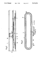
- FIG. 3 A plan view of an "oval" of a suction device with the parallel rails and conveyors.
- FIG. 4 A suction trolley standing ready in the vicinity of the buffer zone in side view.
- the suction device shown in the drawings is used for sucking the exhaust gases from motor vehicles, which perform a trail run during the movement through the conveyor 1 over a test section. For this purpose when the suction trolleys are moved over the said test section they must be so "connected” with the vehicle exhaust that reliable suction takes place.
- the motor vehicles whereof one is diagrammatically indicated in FIG. 2, are moved over a platform 2 by a first conveyor 1, in this case an overhead conveyor.
- a first conveyor 1 in this case an overhead conveyor.
- platform 2 has a slot, below which is positioned a suction slotted duct 4 located between rails 3 which, as shown in FIG. 2, form a continuous, i.e. a closed oval.
- the return section of the rails 3 is designated 5.
- the suction slotted duct 4 with its rials 3 is at a higher level than the return section. Up to said higher level passes an entry section 6 and from it passes downwards on exit section 7.
- a contact rail or busbar 8 is provided for the suction trolleys 20 parallel to the rail 3 (cf. FIG. 3). This contact rail is on the outside.
- a second conveyor 9 which is constructed as a chain conveyor (transversely jointed chain). This second conveyor, which is completely independent of the first, is driven synchronously with the latter, so as to synchronize the movements of the suction trolleys with those of the vehicles.
- Drivers 10 for the individual suction trolleys 20 are provided on the second conveyor 9.
- the suction trolleys 20 comprise a frame 25 on which are mounted the runners 24. The latter run on the rails 3, as can in particular be gathered from FIG. 1.
- Each suction trolley has a suction nozzle 22, which is connected to a suction hood 21 which, through a slot in the platform 2, projects above the latter and onto the plane of the vehicle exhaust.
- the suction nozzle 22 passes through an elastic lip-type packing 23 of the fixed suction slotted duct 4 and opens the latter and consequently forms the connection with the vacuum within said duct 4.
- the suction slotted duct 4 is located between the latter (FIG. 3) and on a higher level (FIG. 2).
- An electromagnet 29 in a casing 28 is located on the frame 25.
- This electromagnet operates a pawl 30, whose two positions can be gathered from FIG. 1.
- the electromagnet is connected via electric lines 27 to contacts 26, which engage in the contact rail 8. It can be seen that as a function of whether the electromagnet 29 is supplied with power or not, the pawl 30 assumes a position where engagement takes place with a driver 10, or a position where the connection with the second conveyor 9 is interrupted.
- the contact rail is subdivided into individual, electrically separated and independently engageable and disengageable switching sections. Certain of these are shown in FIG. 3 and are designated 14 to 19.
- the switching sections 14 to 16 form a buffer zone, where the suction trolleys are made ready prior to coupling in.
- the final switching section 14 in the conveying direction is the starting section.
- the corresponding suction trolley 20 is started at precisely that time which ensures that on accelerating to the entry section 6 it connects with the associated exhaust.
- a special combination and arrangement of sensors and switches permits a vehicle length interrogation and supplies the starting signal for the suction trolley in the starting position. Thus, it is possible for each random vehicle to start a suction trolley at the correct moment.
- each suction trolley 20 is provided a photocell (reflection light sensor) 31 which, on approaching a preceding or stationary suction trolley, ensures that the pawl separates its trolley from the driver and consequently movement is interrupted. This preferably takes place in the buffer zone.
- a lock 13 which has a section of the rails 3 in the return section 5, which can be laterally moved out, in order to carry out the introduction or removal of suction trolleys on a repair rail 12 or a switching or shunting rail 11.
- short switching sections 18, 19 for the contact rail 8, so as to perform the corresponding control pulses are provided.
- the lock is preferably moved pneumatically. A moving out of suction trolleys takes place e.g. for repair or maintenance purposes.
- a special sensor system checks that the top of the suction trolley is correctly seated on the bottom. If there is a reciprocal displacement between the top and bottom, this is detected and the defective suction trolley is automatically moved out.
- a stopping section Shortly prior to the moving out section 7 is provided a stopping section with a corresponding switching section 17 in the contact rail 8, so as to ensure a brief stoppage of the suction trolley and therefore a reliable separation from the exhaust prior to the movement of the lower level in the return section.
- a suction trolley is in the starting position in switching section 14.
- the motor vehicle has reached the corresponding position on the first conveyor 1
- power is supplied to the electromagnet 29 on said suction trolley 20 and the second conveyor moves the trolley synchronously with the vehicle in such a way that after accelerating to the entry section 6 it is connected to the exhaust, i.e. the suction hood 21 is moved over the exhaust.
- the suction trolleys ready in the buffer zone are correspondingly moved in the conveying direction, so that the next suction trolley is in the starting position.
- Separation takes place correspondingly, particularly by a "stop signal" for the switching section 17 of the contact rail 8 and consequently for a brief interruption of the movement of the trolley for separation.
- the suction trolley is moved back in the direction of the buffer zone on the return section 5. It can optionally be moved out in the lock 13, if this is necessary for repair or maintenance purposes.
- the suction hood is connected by a mechanically separable safety coupling (ball latch) to the associated suction trolley, so that there is a mechanical separation of these parts, e.g. on striking an obstacle.
- a mechanically separable safety coupling ball latch
Abstract
Description
Claims (11)
Applications Claiming Priority (2)
| Application Number | Priority Date | Filing Date | Title |
|---|---|---|---|
| DE8914191[U] | 1989-12-01 | ||
| DE8914191U DE8914191U1 (en) | 1989-12-01 | 1989-12-01 |
Publications (1)
| Publication Number | Publication Date |
|---|---|
| US5127875A true US5127875A (en) | 1992-07-07 |
Family
ID=6845097
Family Applications (1)
| Application Number | Title | Priority Date | Filing Date |
|---|---|---|---|
| US07/616,364 Expired - Fee Related US5127875A (en) | 1989-12-01 | 1990-11-21 | Suction device for the exhaust gases of motor vehicles |
Country Status (5)
| Country | Link |
|---|---|
| US (1) | US5127875A (en) |
| EP (1) | EP0429927B1 (en) |
| JP (1) | JPH03186387A (en) |
| DE (2) | DE8914191U1 (en) |
| ES (1) | ES2040547T3 (en) |
Families Citing this family (2)
| Publication number | Priority date | Publication date | Assignee | Title |
|---|---|---|---|---|
| DE9412317U1 (en) * | 1994-07-30 | 1995-06-14 | Ludscheidt Gmbh | Device for coupling and uncoupling track-guided exhaust gas extraction vehicles from an entrainer |
| JP2008305963A (en) | 2007-06-07 | 2008-12-18 | Yamaha Motor Co Ltd | Part recognizer, part mounting machine and part testing machine |
Citations (5)
| Publication number | Priority date | Publication date | Assignee | Title |
|---|---|---|---|---|
| US3602128A (en) * | 1968-05-13 | 1971-08-31 | Erik Allan Lindkvist | Exhaust systems for removal of fumes |
| US4087333A (en) * | 1976-05-27 | 1978-05-02 | Wilputte Corporation | Traveling hood for coke oven emission control |
| US4389923A (en) * | 1980-04-19 | 1983-06-28 | Horst Ludscheidt | Exhaust apparatus for removing pollutants |
| US4660465A (en) * | 1984-08-18 | 1987-04-28 | Horst Jentzsch | System for exhausting and collecting gases, in particular motor vehicle exhaust gases in assembly or factory halls |
| US4724751A (en) * | 1985-07-16 | 1988-02-16 | Horst Jentzsch | System for exhausting and collecting gases, in particular motor vehicle exhaust gases in assembly or factory halls |
Family Cites Families (2)
| Publication number | Priority date | Publication date | Assignee | Title |
|---|---|---|---|---|
| DE2246043B2 (en) * | 1972-09-20 | 1979-02-22 | Christian O. 7314 Wernau Gruhl | Exhaust extraction system |
| DE8427012U1 (en) * | 1984-09-13 | 1988-11-10 | Jentzsch, Horst, 7447 Aichtal, De |
-
1989
- 1989-12-01 DE DE8914191U patent/DE8914191U1/de not_active Expired - Lifetime
-
1990
- 1990-11-10 ES ES199090121539T patent/ES2040547T3/en not_active Expired - Lifetime
- 1990-11-10 EP EP90121539A patent/EP0429927B1/en not_active Expired - Lifetime
- 1990-11-10 DE DE9090121539T patent/DE59001046D1/en not_active Expired - Fee Related
- 1990-11-21 US US07/616,364 patent/US5127875A/en not_active Expired - Fee Related
- 1990-11-29 JP JP2326127A patent/JPH03186387A/en active Pending
Patent Citations (5)
| Publication number | Priority date | Publication date | Assignee | Title |
|---|---|---|---|---|
| US3602128A (en) * | 1968-05-13 | 1971-08-31 | Erik Allan Lindkvist | Exhaust systems for removal of fumes |
| US4087333A (en) * | 1976-05-27 | 1978-05-02 | Wilputte Corporation | Traveling hood for coke oven emission control |
| US4389923A (en) * | 1980-04-19 | 1983-06-28 | Horst Ludscheidt | Exhaust apparatus for removing pollutants |
| US4660465A (en) * | 1984-08-18 | 1987-04-28 | Horst Jentzsch | System for exhausting and collecting gases, in particular motor vehicle exhaust gases in assembly or factory halls |
| US4724751A (en) * | 1985-07-16 | 1988-02-16 | Horst Jentzsch | System for exhausting and collecting gases, in particular motor vehicle exhaust gases in assembly or factory halls |
Also Published As
| Publication number | Publication date |
|---|---|
| JPH03186387A (en) | 1991-08-14 |
| EP0429927A3 (en) | 1992-04-29 |
| ES2040547T3 (en) | 1993-10-16 |
| DE59001046D1 (en) | 1993-04-22 |
| DE8914191U1 (en) | 1990-01-11 |
| EP0429927A2 (en) | 1991-06-05 |
| EP0429927B1 (en) | 1993-03-17 |
Similar Documents
| Publication | Publication Date | Title |
|---|---|---|
| US5257431A (en) | Airplane loading bridge | |
| US4660465A (en) | System for exhausting and collecting gases, in particular motor vehicle exhaust gases in assembly or factory halls | |
| US1901928A (en) | Automatic spacer | |
| US4987834A (en) | Accumulating conveyor with self-propelled pallets | |
| US5105495A (en) | Airplane loading bridge | |
| JPH06211480A (en) | Detector for missing of footstep of escalator | |
| US3828681A (en) | Conveyor systems | |
| US5127875A (en) | Suction device for the exhaust gases of motor vehicles | |
| US5305693A (en) | System and method for externally controlled spacing of self propelled vehicles along a rail | |
| GB1253074A (en) | ||
| KR100595733B1 (en) | A Contact - Free Type Door Control System with Proximity Switch | |
| US6418855B1 (en) | Industrial truck | |
| JP3691653B2 (en) | Conveying device on the route of automatic guided vehicle | |
| GB1043634A (en) | Improvements in or relating to basket cart conveyor systems | |
| US4724751A (en) | System for exhausting and collecting gases, in particular motor vehicle exhaust gases in assembly or factory halls | |
| US5116002A (en) | Stopping zones in a linear motor in-track transit system | |
| US5570637A (en) | Garage for a continuous cable railway | |
| JPH07237544A (en) | Runaway preventing device for conveying carriage in branching ad joining point device | |
| EP0158421A1 (en) | Door close mechanism | |
| JPH02182613A (en) | Load conveyor device | |
| CN112055762B (en) | Bale opener for opening compressed fiber bales with collision protection system | |
| JP2678773B2 (en) | Transportation control system for transportation trains | |
| US1208060A (en) | Electrical transportation system. | |
| KR970001064Y1 (en) | Safety equipment for escalator step operation | |
| US4203370A (en) | In-floor towline automatic re-entry spur |
Legal Events
| Date | Code | Title | Description |
|---|---|---|---|
| AS | Assignment |
Owner name: NORFI NORDFILTER-ANLAGENBAU GMBH, ZEISS-STRASSE 3, Free format text: ASSIGNMENT OF ASSIGNORS INTEREST.;ASSIGNORS:FUHRMANN, ULRICH;SPIEGEL, MICHAEL;FIBELKORN, TORSTEN;REEL/FRAME:005523/0622;SIGNING DATES FROM 19901119 TO 19901120 |
|
| FEPP | Fee payment procedure |
Free format text: PAYOR NUMBER ASSIGNED (ORIGINAL EVENT CODE: ASPN); ENTITY STATUS OF PATENT OWNER: SMALL ENTITY |
|
| FPAY | Fee payment |
Year of fee payment: 4 |
|
| AS | Assignment |
Owner name: NORFI-EXHAUST EXTRACTION SYSTEM GMBH, GERMANY Free format text: ASSIGNMENT OF ASSIGNORS INTEREST;ASSIGNOR:NORFI NORDFILTER-ANLAGENBAU GMBH;REEL/FRAME:008200/0544 Effective date: 19960418 |
|
| FEPP | Fee payment procedure |
Free format text: PAYER NUMBER DE-ASSIGNED (ORIGINAL EVENT CODE: RMPN); ENTITY STATUS OF PATENT OWNER: SMALL ENTITY Free format text: PAYOR NUMBER ASSIGNED (ORIGINAL EVENT CODE: ASPN); ENTITY STATUS OF PATENT OWNER: SMALL ENTITY |
|
| FEPP | Fee payment procedure |
Free format text: PAYER NUMBER DE-ASSIGNED (ORIGINAL EVENT CODE: RMPN); ENTITY STATUS OF PATENT OWNER: SMALL ENTITY Free format text: PAYOR NUMBER ASSIGNED (ORIGINAL EVENT CODE: ASPN); ENTITY STATUS OF PATENT OWNER: SMALL ENTITY |
|
| REMI | Maintenance fee reminder mailed | ||
| LAPS | Lapse for failure to pay maintenance fees | ||
| FP | Lapsed due to failure to pay maintenance fee |
Effective date: 20000707 |
|
| STCH | Information on status: patent discontinuation |
Free format text: PATENT EXPIRED DUE TO NONPAYMENT OF MAINTENANCE FEES UNDER 37 CFR 1.362 |