US511307A - Railway time-signal - Google Patents
Railway time-signal Download PDFInfo
- Publication number
- US511307A US511307A US511307DA US511307A US 511307 A US511307 A US 511307A US 511307D A US511307D A US 511307DA US 511307 A US511307 A US 511307A
- Authority
- US
- United States
- Prior art keywords
- rail
- indicating
- chamber
- liquid
- diaphragm
- Prior art date
- Legal status (The legal status is an assumption and is not a legal conclusion. Google has not performed a legal analysis and makes no representation as to the accuracy of the status listed.)
- Expired - Lifetime
Links
- 239000007788 liquid Substances 0.000 description 34
- 229920001971 elastomer Polymers 0.000 description 6
- LFQSCWFLJHTTHZ-UHFFFAOYSA-N Ethanol Chemical compound CCO LFQSCWFLJHTTHZ-UHFFFAOYSA-N 0.000 description 4
- 239000010985 leather Substances 0.000 description 4
- 238000010276 construction Methods 0.000 description 3
- 230000000994 depressogenic effect Effects 0.000 description 3
- 239000004744 fabric Substances 0.000 description 3
- 230000006872 improvement Effects 0.000 description 3
- 230000007246 mechanism Effects 0.000 description 3
- 238000004040 coloring Methods 0.000 description 2
- 239000011521 glass Substances 0.000 description 2
- 239000000463 material Substances 0.000 description 2
- 239000002184 metal Substances 0.000 description 2
- 229910052751 metal Inorganic materials 0.000 description 2
- 239000002244 precipitate Substances 0.000 description 2
- 229910001018 Cast iron Inorganic materials 0.000 description 1
- 244000286663 Ficus elastica Species 0.000 description 1
- RRHGJUQNOFWUDK-UHFFFAOYSA-N Isoprene Chemical compound CC(=C)C=C RRHGJUQNOFWUDK-UHFFFAOYSA-N 0.000 description 1
- NINIDFKCEFEMDL-UHFFFAOYSA-N Sulfur Chemical compound [S] NINIDFKCEFEMDL-UHFFFAOYSA-N 0.000 description 1
- 239000005864 Sulphur Substances 0.000 description 1
- 238000009825 accumulation Methods 0.000 description 1
- 230000009471 action Effects 0.000 description 1
- 230000001154 acute effect Effects 0.000 description 1
- 230000008901 benefit Effects 0.000 description 1
- 239000003086 colorant Substances 0.000 description 1
- 150000001875 compounds Chemical class 0.000 description 1
- 230000007797 corrosion Effects 0.000 description 1
- 238000005260 corrosion Methods 0.000 description 1
- 230000000881 depressing effect Effects 0.000 description 1
- 230000003292 diminished effect Effects 0.000 description 1
- 210000003414 extremity Anatomy 0.000 description 1
- 230000003137 locomotive effect Effects 0.000 description 1
- 150000002739 metals Chemical class 0.000 description 1
- 230000004048 modification Effects 0.000 description 1
- 238000012986 modification Methods 0.000 description 1
- 238000005192 partition Methods 0.000 description 1
- 229920001195 polyisoprene Polymers 0.000 description 1
- 230000000284 resting effect Effects 0.000 description 1
- 238000010008 shearing Methods 0.000 description 1
- 230000035939 shock Effects 0.000 description 1
- 230000000153 supplemental effect Effects 0.000 description 1
- 210000001364 upper extremity Anatomy 0.000 description 1
- 239000004636 vulcanized rubber Substances 0.000 description 1
Images

Classifications
-
- F—MECHANICAL ENGINEERING; LIGHTING; HEATING; WEAPONS; BLASTING
- F16—ENGINEERING ELEMENTS AND UNITS; GENERAL MEASURES FOR PRODUCING AND MAINTAINING EFFECTIVE FUNCTIONING OF MACHINES OR INSTALLATIONS; THERMAL INSULATION IN GENERAL
- F16F—SPRINGS; SHOCK-ABSORBERS; MEANS FOR DAMPING VIBRATION
- F16F9/00—Springs, vibration-dampers, shock-absorbers, or similarly-constructed movement-dampers using a fluid or the equivalent as damping medium
- F16F9/32—Details
- F16F9/44—Means on or in the damper for manual or non-automatic adjustment; such means combined with temperature correction
Definitions
- BENJAMIN B MORGAN, OF YPSILANTI, MICHIGAN.
- My invention relates to railroad time signals, and consists in certain improvements hereinafter specified upon the apparatus described and illustrated by me in myapplication filed May 12, 1892, Serial No. 432,741, for railroad time signals.
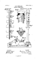
- Figure 1 is an elevation of the time signal, showing the rail connections and apparatus part in section, and certain improvements in the indicating apparatus hereinafter described.
- Fig. 2 is a sectional view of the upper portion of Fig. 1.
- Fig. 3 is a plan view of the track connection and apparatus, showing the manner of arranging the spring connecting rail in its relation to the track.
- Fig. 4 is a sectional elevation of the receiving and compressing chamberfortheliquid.
- Fig.5 illustrates thecentral block or bearing holding the spring rail in position.
- Fig. 6 shows the end bearings for the same.
- Fig. 7 is a vertical transverse section of the indicating chamber as improved.
- Fig.8 is a cross section of Fig. 7 on line w:r.
- Fig. 9 is a vertical section of the case at the bottom of the standard, showing the operating lever.
- A represents the standard which is preferably erected upon timbers or cross ties extending under the track B.
- O is a lever which connects the track mechanism with the plunger D.
- This plunger has formed upon its upper extremity the head D, which is connected with the diaphragm E, the details of which are shown in Fig. 4.
- My improved diaphragm is constructed of two or more thicknesses of pure india rubber fabric and leather, they being preferably, although not necessarily, cemented together with the pure rubber face presented to the contained liquid.
- 6 represents the rubber, and e the leather section of the diaphragm.
- pure rubher is the only material for a fabric which is not affected by the alcohol used in the signal, and which, at the same time, will not react upon the coloring matter in the alcohol and precipitate it or make it muddy, and which at the same time absolutely seals and prevents leakage through the diaphragm.
- vulcanized rubber is impractical in this relation, because the sulphur in it decomposes and precipitates the coloring matter dissolved in the alcohol.
- thin metal might be used in theplace of it, but all metals are liable to corrosion more or less, and are hence objectionable on that account.
- a pure rubber diaphragm of itself is not sufficiently strong and is too elastic, and to obtain strength 1 combine it with leather preferably, although strong canvas or other analogous fabrics might be substituted and even incorporated in the rubber.
- the leather section of the diaphragm e is fastened to the flange (l by means of rivets c
- the rivets head are smooth upon the upper side, and do not in any Way interfere with or disturb the form ofthe rubber section 6 of the diaphragm.
- the upper plunger head and diaphragm liquid overflowing therefrom in the top of the glass indicating chamber H.
- a small hole marked f leads from the indicating chamber back into the pipe F. This hole is so proportioned in my improved device that it takes several seconds for theliquid which rises above its orifice in the indicating chamber to fall to its level.
- the lever C, with its attachments, is so proportioned or weighted that the rail attachments upon the one side Very nearly counterbalance the plunger D and its attachments upon the other side. As the weight upon the indicating side is somewhat greater than that upon the rail side, the tendency will be to descend after being elevated by the passage of the wheel over the track connection.
- B is the track, which of course is constructed in the ordinary manner.
- B is a spring wing rail, which is intended to be of suificient length to pass over and connect a number of ties, and is preferably from sixteen to twenty feet in length.
- This wing rail is curved, and rises in the center about an inch above the track, and is depressed gradually in the center to the level of the track by the passage over the track of a heavily loaded wheel, as, the forward truck wheel of a locomotive.
- This gradual depression is quite important, as it prevents too sudden a shock by a quick moving train. It is also made stiff enough so that a hand car will readily pass over it without setting the signal by its depression.
- This hole forms a socket bearing which receives the end of the spring wing rail, they being set at either end at such distances that the end of the spring rail does not extend quite to the depth of the hole in the block, which permits of the extension in length of the rail, due to its straightening caused by the depression of its center.
- both blocks are exactly alike, except that the holes are upon reversed sides, it is unnecessary to describe them further.
- the hole I) in the blocks B B are situated at some inches distant from the side of the rail, and that the spring rail 13' has its ends curved outwardly from the track, as shown at I), b".
- the object of this is to compel the spring rail to hug the side of the main rail by virtue of the force of depression.
- I At the center of the spring rail, I have placed a long block extending across two ties, shown in Fig. 5 and lettered B which is of peculiar construction. Its upper edge is situated at a distance from the main rail B measured by the thickness of the spring rail B. It thus, combined with the main rail, forms a guide for the perpendicular movement of the center of the spring rail.
- FIG. 1 A central cross section of this block B is more particularly shown in Fig. 1, showing the wing rail, the main rail,and block, with lugs in position.
- the upper surface ofthe bearing flange of the main rail B has an outward slope. This slope, in conjunction with the under surface of the spring rail B, prevents any accumulation of snow or ice underneath the spring rail, thus tending to prevent its proper action as the pressure of the wheel upon the spring rail crowding ice and snow down upon the sloping flange of the main rail, presses it outwardly down the flange. There is also avoided any necessity of keeping the parts free from snow or ice, as has heretofore been found necessary in this general class of track connections.
- the central portion of the block-B is cut away, as shown in Figs.
- Supplemental blocks B 13 may be used intermediately between the central block B and end blocks B to still more firmly confine the spring rail B to main rail, if the same is found desirable. They are therefore shown in Fig. 3, but as they do not constitute any of the essence of the invention, they are not further described.
- the object of this is that if, in case of the stoppage of a train after passing the signal, it be necessary to notify succeeding trains, a brakeman can return from the stalled train, unlock door a, and, by means of the lever, set the signal, which will thus remain in position indicating danger, and showing that a train has immediately passed, so long as the lever L remains in position thus set.
- the lever L is released, the signal of course will gradur,
- Fig. 1 there is shown at ra pet-cock
- This means consists in the placing and supportingby its edges of a perpendiculardiaphragm centrally placed in the indicating chamber, this diaphragm being colored with a colorafiording the best contrast to that of the color of the indicating liquid. If the indicatingliquid be red or any dark color, the preferable contrast would be white, and I deem that the preferable diaphragm is made of an opaquewhite glass. This is illustrated in Fig. 7, which is a vertical section of the indicating chamber, by. S.
- Fig, 8 is a cross section on the line m a: of Fig. 7, looking downward, and indicates the diaphragm S in position andsupported at its edges.
- a sharp line of demarkation is always observable at the upper edge of the indicating liquid, and is not affected by reflected light or the nature of the background, as it is obvious from the drawings and description that the liquid in descending from the overflow pipe into the indicating chamber fills the indicating chamber upon either side of the diaphragm S, and consequently is observed from either direction with the same facility and accuracy, and the fact that the partition S is opaque, instead of being a detriment, thus becomes an advantage, as it prevents any modification by reason of the lights and shades of a country background.
- a center side support consisting of a block having upon one side thereofa flange adapted to be bolted to the cross ties, and lugs projecting from the bottom and opposite side adapted to impinge upon the bottom of the main rail and thus resist the overturn of the block, substantially as described.
- a center side support for the latter consisting ofablock between which and the main rail the auxiliary rail is adapted to descend, said block being adapted to be fastened to the cross ties and slotted in the center, and a lever operating a signal and adapted to move in and be guided bythe slot in said block, substantially as described.
- a chamber containing an indicatingliquid and adapted to have its cubieal contents di minished by the passage of a moving train a plunger attached to the movable side of said chamber, and means connecting said plunger whereby it may be operated to diminish the contents of said chamber upon the passage of a moving train
- an indicating chamber a passage way relatively large leading from the holding chamber described to the top of the indicating chamber, a check valve located at the top of said passage way, a passage way relatively small leading from near the top of the indicating chamber to near the top of the passage way but below said check valve, whereby the liquid may be withdrawn down to the indicating level, all adjusted and operating so that the liquid may be forced very quickly through the larger passage-way into the indicating chamber, and'may be withdrawn slowly from the indicatingchamber down to the indicating level, substantially as and for the purpose described.
- a chamber containing an indicating liquid and adapted to have its cubical contents diminished by the passage of a moving train a plunger attached to the movable side of said chamber, and means connecting said plunger, whereby it may be operated to diminish the contents of said chamber upon the passage of a moving train, an indicating chamber, a passage way relatively large leading from the holding chamber described to the top of the indicating chamber, a check valve located at the top of said passage way, a passage way relatively small leading from near the top of the indicating chamber to near the top of the passage way but below said check valve whereby the liquid may be withdrawn down to the indicating level, all adjusted and operating so that the liquid may be forced very quickly through the larger passage way into the indicating chamber and may be withdrawn slowly from the indicating chamber down to the indicating level, and a collapsible air bag inclosing the upper end of the indicating chamber and the upper end of the large passage way, and adapted to collapse on the drawing off of the liquid, substantially as described
- a compound diaphragm of which the face on the side in contact with the liquid is composed of pure rubber combined with a backing of flexible material to which the actuating plunger is centrally attached, substantially as described and for the purpose set forth.
- a liquid. time signal the combination of an outer case perforated upon each side by oblong apertures for the purpose of observation, and having thereon indicating marks whereby the descent of the liquid may be measured, a transparent chamber located within said case, a colored liquid adapted to be held within, and fall slowly from said indicating chamber, an intermediate central diaphragm connected with said indicating chamber upon its edges only, whereby the liquid has freeaccess to either side above or below said diaphragm, the diaphragm having a color contrasting with the color of the liquid, and means whereby the said chamber may be filled by the passage of a moving train, and means whereby the liquid maybe withdrawn slowly from said chamber, substantially as and for the purpose described.
- a transparent chamber havingsubstantially a rectangular cross section and a wedge shaped vertical section with the apex downward, a diaphragm vertically centrally located therein and having substantially a rectangnlar cross section, and being substantially opaque and connected by its edges only to the parallel sides of the transparent chamber, a coloredliquid held in said chamber and arising upon either side of the diaphragm, means whereby said chamber may be filled by said liquid by the passage of a moving train, and means whereby said liquid maybe withdrawn slowly from said chamber, said liquid and said diaphragm having contrasted colors, substantially as and for the purpose specified.
Landscapes
- Engineering & Computer Science (AREA)
- General Engineering & Computer Science (AREA)
- Mechanical Engineering (AREA)
- Train Traffic Observation, Control, And Security (AREA)
Description
' (No Model.)
2 Sheets-Sheet ,1. B. B. MORGAN. RAILWAY TIME SIGNAL.
3 Patented Dean 19, 1893.
u ,1 flai /ii? wwwwwwwwwwwww c.
UNITED STATES PATENT OFFICE.
BENJAMIN B. MORGAN, OF YPSILANTI, MICHIGAN.
RAILWAY TIME-SIGNAL.
SPECIFICATION forming part of Letters Patent No. 511,307, dated December 19, 1893.
Application filed December 27, 1892. Serial No. 456,419- (No model.)
To all whom it 12mg concern/.-
Be it known that I, BENJAMIN B. MORGAN, a citizen of the United States, residing at Ypsilanti, county of Washtenaw, State of Michigan, have invented a certain new and useful Improvement in Railway Time-Signals; and I declare the following to be a full, clear, and exact description of the same, such as will enable others skilled in the art to which it pertains to make and use the same, reference being had to the accompanying drawings, which form a part of this specification.
My invention relates to railroad time signals, and consists in certain improvements hereinafter specified upon the apparatus described and illustrated by me in myapplication filed May 12, 1892, Serial No. 432,741, for railroad time signals.
In the drawings, Figure 1 is an elevation of the time signal, showing the rail connections and apparatus part in section, and certain improvements in the indicating apparatus hereinafter described. Fig. 2 is a sectional view of the upper portion of Fig. 1. Fig. 3 is a plan view of the track connection and apparatus, showing the manner of arranging the spring connecting rail in its relation to the track. Fig. 4 is a sectional elevation of the receiving and compressing chamberfortheliquid. Fig.5illustrates thecentral block or bearing holding the spring rail in position. Fig. 6 shows the end bearings for the same. Fig. 7 is a vertical transverse section of the indicating chamber as improved. Fig.8 is a cross section of Fig. 7 on line w:r. Fig. 9 is a vertical section of the case at the bottom of the standard, showing the operating lever.
Similar-letters refer to similar parts.
In the drawings, A represents the standard which is preferably erected upon timbers or cross ties extending under the track B.
O is a lever which connects the track mechanism with the plunger D. This plunger has formed upon its upper extremity the head D, which is connected with the diaphragm E, the details of which are shown in Fig. 4.
My improved diaphragm is constructed of two or more thicknesses of pure india rubber fabric and leather, they being preferably, although not necessarily, cemented together with the pure rubber face presented to the contained liquid.
In the drawings, 6 represents the rubber, and e the leather section of the diaphragm. I have found that so faras I know, pure rubher is the only material for a fabric which is not affected by the alcohol used in the signal, and which, at the same time, will not react upon the coloring matter in the alcohol and precipitate it or make it muddy, and which at the same time absolutely seals and prevents leakage through the diaphragm. I find that vulcanized rubber is impractical in this relation, because the sulphur in it decomposes and precipitates the coloring matter dissolved in the alcohol. As suggested in my former application, thin metal might be used in theplace of it, but all metals are liable to corrosion more or less, and are hence objectionable on that account. They would undoubtedly last for a time, but would require frequent renewals. A pure rubber diaphragm of itself is not sufficiently strong and is too elastic, and to obtain strength 1 combine it with leather preferably, although strong canvas or other analogous fabrics might be substituted and even incorporated in the rubber.
In my improved device, I firmly attach the head to the diaphragm for purposes which will hereinafter appear, which is also illustrated in Fig. 4. The upper portion of the head has inserted therein in a recess properly constructed for that purpose a bolt 61 A pin, (1 secures and prevents it from turning after it is onceinserted. The upper portion of this bolt (1 has formed thereon a flanged head CF. The upper portion of the head is formed to correspond with the shape of the upper end of the plunger, being a section of a sphere. The leather section of the diaphragm e is fastened to the flange (l by means of rivets c The rivets head are smooth upon the upper side, and do not in any Way interfere with or disturb the form ofthe rubber section 6 of the diaphragm. By this construction the upper plunger head and diaphragm liquid overflowing therefrom in the top of the glass indicating chamber H. As described in my former application, a small hole marked f leads from the indicating chamber back into the pipe F. This hole is so proportioned in my improved device that it takes several seconds for theliquid which rises above its orifice in the indicating chamber to fall to its level. The check valve fat the top of the pipe F closing the moment the flow upward ceases, substantially all of the liquid must flow back through the hole f, and, as no air can enter downward in through the check valve, the result is that there is a tendency to hold upward at the extremity of its throw the plunger head D and the diaphragm E, as indicated by the dotted lines in Fig. at. The lever C, with its attachments, is so proportioned or weighted that the rail attachments upon the one side Very nearly counterbalance the plunger D and its attachments upon the other side. As the weight upon the indicating side is somewhat greater than that upon the rail side, the tendency will be to descend after being elevated by the passage of the wheel over the track connection. This tendency to descend is resisted by the suction through the small hole f, as described. i It results that, on the passage of the train, the first wheel will set the signal, and that perhaps the whole train will then pass before the device will be operated by another wheel. In case it does not wholly pass, another wheel would drive the plunger up, where it would remain long enough for the train to have passed entirely. It will be seen that, by thus making the check valve tight, proportioning the opening f so that the liquid in descending to the indicating level must move upwardly slowly through it, connecting the plunger head. D to the diaphragm, and very nearly conterbalancing the weight on the opposite sides of the lever C, I am enabled to dispense with dash pots or any analogous device, and to prevent excessive churning or vibration of the diaphragm and all the attending mechanism by the passage of trains, however long. My improved track connection, which is more particularly shown in Figs. 1, 3, 5 and 6, materially assists in this, as there is no rigid connection between the track end of lever O and the spring rail which I have devised and use forthe purpose of depressing the end of the lever 0, instead of the rail of the track.
In Fig. 3, B is the track, which of course is constructed in the ordinary manner. B is a spring wing rail, which is intended to be of suificient length to pass over and connect a number of ties, and is preferably from sixteen to twenty feet in length. This wing rail is curved, and rises in the center about an inch above the track, and is depressed gradually in the center to the level of the track by the passage over the track of a heavily loaded wheel, as, the forward truck wheel of a locomotive. This gradual depression is quite important, as it prevents too sudden a shock by a quick moving train. It is also made stiff enough so that a hand car will readily pass over it without setting the signal by its depression.
Iain aware that spring wing rails for the purpose of track connections are old,but they have been open to objections which have prevented their use, and these objections Ihave obviated in the mechanism described and illustrated in Figs. 3, 5 and 6.
As a support to the wing rail, I provide at either end heavy cast iron blocks, 13*, as illustrated in Fig. 6. The block extends up to and touches the top of the rail, as shown at either end in Fig. 3, at B B The lower side of the block adjacent to the rail is cut away, as shown at h in Fig. 6. This is intended to accommodate the lower flange of the rail, the block resting thereon. Upon the opposite side of the block 13 there projects a flange which is perforated with holes, and is thus adapted to be spiked or bolted down upon the tie upon which it rests. The block B is perforated with a square hole extending nearly through it, and shown in Fig. 6 at If. This hole forms a socket bearing which receives the end of the spring wing rail, they being set at either end at such distances that the end of the spring rail does not extend quite to the depth of the hole in the block, which permits of the extension in length of the rail, due to its straightening caused by the depression of its center. As both blocks are exactly alike, except that the holes are upon reversed sides, it is unnecessary to describe them further.
It will be noticed'that the hole I) in the blocks B B are situated at some inches distant from the side of the rail, and that the spring rail 13' has its ends curved outwardly from the track, as shown at I), b". The object of this is to compel the spring rail to hug the side of the main rail by virtue of the force of depression. At the center of the spring rail, I have placed a long block extending across two ties, shown in Fig. 5 and lettered B which is of peculiar construction. Its upper edge is situated at a distance from the main rail B measured by the thickness of the spring rail B. It thus, combined with the main rail, forms a guide for the perpendicular movement of the center of the spring rail. Its rear portion is flanged, and is adapted by means of bolt holes to be bolted or spiked to two cross ties in the same manner as in the block B Underneath the block B are formed two lugs or projections 12 12 which are solidly cast with the block, and are intended to fit the under surface of the main rail. This forms a strong construction, as the upper edge of the block cannot be forced away from the main rail without either raising the main rail by virtue of the lugs, or shearing the spikes or bolts which hold the block to the ties. A central cross section of this block B is more particularly shown in Fig. 1, showing the wing rail, the main rail,and block, with lugs in position. It will be observed that the upper surface ofthe bearing flange of the main rail B has an outward slope. This slope, in conjunction with the under surface of the spring rail B, prevents any accumulation of snow or ice underneath the spring rail, thus tending to prevent its proper action as the pressure of the wheel upon the spring rail crowding ice and snow down upon the sloping flange of the main rail, presses it outwardly down the flange. There is also avoided any necessity of keeping the parts free from snow or ice, as has heretofore been found necessary in this general class of track connections. The central portion of the block-B is cut away, as shown in Figs. 5 and 1, at b Attached to the track end of the lever O by a ball and socket joint, shown at c, is a curved arm C. This arm rises in the recess b in block B and is'guided by it with its upper end curving toward the track and projecting under the spring rail B. As it is not attached to the spring rail, but only receives motion from it when it is depressed, it does not necessarily return with it when the spring rail rises after depression; but, as hereinbefore explained, it remains depressed in the dotted position until the liquid has reached the indicating level by its flowing through the hole f, as shown in.
Fig. 2. Supplemental blocks B 13 may be used intermediately between the central block B and end blocks B to still more firmly confine the spring rail B to main rail, if the same is found desirable. They are therefore shown in Fig. 3, but as they do not constitute any of the essence of the invention, they are not further described.
The lower end of the standard A rests upon the casing A, shown enlarged in Fig. 9, and within this casing in any convenient position there is out a door, a. This door may be closed and locked by any suitable means. i Inside of the casing, and pivoted to thetimber support or continuation of the ties, is a bell crank lever L, returning from the pivotal point m at an acute angle, the arm being it. The arms of this lever are so proportioned that, by rotating it in the proper direction, the indicating end of the lever C is raised, forcing upward the plunger with its head D, and thus the indicating liquid is compelled to overflow into the indicating chamber, and as, so long as the leverL is not reversed, the lever 0 must remain in position with the plunger D forced upward as hereinbefore stated, the signal will continue to be set showing danger. The object of this is that if, in case of the stoppage of a train after passing the signal, it be necessary to notify succeeding trains, a brakeman can return from the stalled train, unlock door a, and, by means of the lever, set the signal, which will thus remain in position indicating danger, and showing that a train has immediately passed, so long as the lever L remains in position thus set. When the lever L is released, the signal of course will gradur,
.ally run down and indicate that the way i clear.
In Fig. 1 there is shown at ra pet-cock,
' opening forwithdrawing the liquid from the indicating chamberin' casethe aperture m easuring its descent should become clogged. Means are provided whereby the whole section containing the aperture can be withdrawn from position.
As shown in the application heretofore mentioned, to wit, Serial No. 432,741, theobservation of the descent of the colored liquid within the indicating chamber through the windows in the case, was by means of the contrast between the color of the liquid and the country background upon the opposite side from the observer. This means was not wholly reliable, and at many times was not distinguishable with a sufficient degree of certainty, so that there was not a sharp line ofdemarkationbetween the liquid and the background. I have devised means forovercoming this difficulty, which means are illustrated in Figs. 7 and 8. This means consists in the placing and supportingby its edges of a perpendiculardiaphragm centrally placed in the indicating chamber, this diaphragm being colored with a colorafiording the best contrast to that of the color of the indicating liquid. If the indicatingliquid be red or any dark color, the preferable contrast would be white, and I deem that the preferable diaphragm is made of an opaquewhite glass. This is illustrated in Fig. 7, which is a vertical section of the indicating chamber, by. S.
Fig, 8 is a cross section on the line m a: of Fig. 7, looking downward, and indicates the diaphragm S in position andsupported at its edges. By this means, a sharp line of demarkation is always observable at the upper edge of the indicating liquid, and is not affected by reflected light or the nature of the background, as it is obvious from the drawings and description that the liquid in descending from the overflow pipe into the indicating chamber fills the indicating chamber upon either side of the diaphragm S, and consequently is observed from either direction with the same facility and accuracy, and the fact that the partition S is opaque, instead of being a detriment, thus becomes an advantage, as it prevents any modification by reason of the lights and shades of a country background.
What I claim isl. In a track connection for time signals,
the combination with the main rail of the ing upon but notconnected with alever oper* ating the time signal, substantially as described.
2. In combination with a spring auxiliary rail adapted to descend in the center and operate a signal, a center side support consisting of a block having upon one side thereofa flange adapted to be bolted to the cross ties, and lugs projecting from the bottom and opposite side adapted to impinge upon the bottom of the main rail and thus resist the overturn of the block, substantially as described.
8. In combination with the main railanda spring auxiliary rail, a center side support for the latter, consisting ofablock between which and the main rail the auxiliary rail is adapted to descend, said block being adapted to be fastened to the cross ties and slotted in the center, and a lever operating a signal and adapted to move in and be guided bythe slot in said block, substantially as described.
4. In a liquid time signal, the combination of a chamber containing an indicatingliquid and adapted to have its cubieal contents di minished by the passage of a moving train,a plunger attached to the movable side of said chamber, and means connecting said plunger whereby it may be operated to diminish the contents of said chamber upon the passage of a moving train, an indicating chamber, a passage way relatively large leading from the holding chamber described to the top of the indicating chamber, a check valve located at the top of said passage way, a passage way relatively small leading from near the top of the indicating chamber to near the top of the passage way but below said check valve, whereby the liquid may be withdrawn down to the indicating level, all adjusted and operating so that the liquid may be forced very quickly through the larger passage-way into the indicating chamber, and'may be withdrawn slowly from the indicatingchamber down to the indicating level, substantially as and for the purpose described.
5. In a liquid time signal, the combination of a chamber containing an indicating liquid and adapted to have its cubical contents diminished by the passage of a moving train, a plunger attached to the movable side of said chamber, and means connecting said plunger, whereby it may be operated to diminish the contents of said chamber upon the passage of a moving train, an indicating chamber, a passage way relatively large leading from the holding chamber described to the top of the indicating chamber, a check valve located at the top of said passage way, a passage way relatively small leading from near the top of the indicating chamber to near the top of the passage way but below said check valve whereby the liquid may be withdrawn down to the indicating level, all adjusted and operating so that the liquid may be forced very quickly through the larger passage way into the indicating chamber and may be withdrawn slowly from the indicating chamber down to the indicating level, and a collapsible air bag inclosing the upper end of the indicating chamber and the upper end of the large passage way, and adapted to collapse on the drawing off of the liquid, substantially as described.
6. In a liquid time signal, in combination with the wallsof a chamber adapted to be reduced in cubical contents by the passage ofa moving train, and with the colored alcohol contained therein, a compound diaphragm of which the face on the side in contact with the liquid is composed of pure rubber combined with a backing of flexible material to which the actuating plunger is centrally attached, substantially as described and for the purpose set forth.
7. In a liquid. time signal, the combination of an outer case perforated upon each side by oblong apertures for the purpose of observation, and having thereon indicating marks whereby the descent of the liquid may be measured, a transparent chamber located within said case, a colored liquid adapted to be held within, and fall slowly from said indicating chamber, an intermediate central diaphragm connected with said indicating chamber upon its edges only, whereby the liquid has freeaccess to either side above or below said diaphragm, the diaphragm having a color contrasting with the color of the liquid, and means whereby the said chamber may be filled by the passage of a moving train, and means whereby the liquid maybe withdrawn slowly from said chamber, substantially as and for the purpose described.
8. In a liquid time signal, the combination of a transparent chamber havingsubstantially a rectangular cross section and a wedge shaped vertical section with the apex downward, a diaphragm vertically centrally located therein and having substantially a rectangnlar cross section, and being substantially opaque and connected by its edges only to the parallel sides of the transparent chamber,a coloredliquid held in said chamber and arising upon either side of the diaphragm, means whereby said chamber may be filled by said liquid by the passage of a moving train, and means whereby said liquid maybe withdrawn slowly from said chamber, said liquid and said diaphragm having contrasted colors, substantially as and for the purpose specified.
9. In combination with a liquid time signal and means whereby the same may be operated on the passage of a moving train, the lever L, whereby the same may be operated by hand and held to the position indicating danger, ac cording to the will of the operator, substantially as described.
In testimony whereof I sign this specification in the presence of two witnesses.
BENJAMIN B. MORGAN.
Witnesses:
MARION A. REEVE, R. A. PARKER.
Publications (1)
| Publication Number | Publication Date |
|---|---|
| US511307A true US511307A (en) | 1893-12-19 |
Family
ID=2580130
Family Applications (1)
| Application Number | Title | Priority Date | Filing Date |
|---|---|---|---|
| US511307D Expired - Lifetime US511307A (en) | Railway time-signal |
Country Status (1)
| Country | Link |
|---|---|
| US (1) | US511307A (en) |
-
0
- US US511307D patent/US511307A/en not_active Expired - Lifetime
Similar Documents
| Publication | Publication Date | Title |
|---|---|---|
| US511307A (en) | Railway time-signal | |
| US1616809A (en) | Railway-crossing signal | |
| US694008A (en) | Automatic audible signaling on railways. | |
| US1364490A (en) | Ses paent offlxe | |
| US865742A (en) | Railway-switch and automatic signal apparatus. | |
| US1497336A (en) | Oil or air operated crossing signal | |
| US494509A (en) | Benjamin b | |
| US494136A (en) | David albert ghent and octavius sydney colbran | |
| US991339A (en) | Railway signaling mechanism. | |
| US905080A (en) | Railway safety appliance. | |
| US181833A (en) | Improvement in automatic railroad-signals | |
| US450062A (en) | Automatic water-elevator | |
| US839664A (en) | Automatic safety alarm apparatus for railway-crossings. | |
| US358201A (en) | Signal for railway draw-bridges | |
| US267321A (en) | Car-coupling | |
| US722187A (en) | Snow-removing flanger. | |
| US194992A (en) | Improvement in railroad-signals | |
| US433906A (en) | Railway time-signal | |
| US338720A (en) | Automatic railroad-signal | |
| US534511A (en) | Half to charles john badger | |
| US156289A (en) | Improvement in time-signals for railroads | |
| US481535A (en) | Sanding device for street-cars | |
| US490799A (en) | Car-coupling | |
| US1394303A (en) | Train-stop | |
| US246405A (en) | Water-column for railroad water-tanks |