US5073741A - Igniter plug - Google Patents
Igniter plug Download PDFInfo
- Publication number
- US5073741A US5073741A US07/635,730 US63573090A US5073741A US 5073741 A US5073741 A US 5073741A US 63573090 A US63573090 A US 63573090A US 5073741 A US5073741 A US 5073741A
- Authority
- US
- United States
- Prior art keywords
- ground electrode
- metallic shell
- lock arms
- insulator
- igniter plug
- Prior art date
- Legal status (The legal status is an assumption and is not a legal conclusion. Google has not performed a legal analysis and makes no representation as to the accuracy of the status listed.)
- Expired - Lifetime
Links
- 239000012212 insulator Substances 0.000 claims abstract description 24
- 238000003466 welding Methods 0.000 claims abstract description 15
- 238000005219 brazing Methods 0.000 claims description 3
- 238000002485 combustion reaction Methods 0.000 description 5
- 239000011521 glass Substances 0.000 description 4
- 230000003647 oxidation Effects 0.000 description 4
- 238000007254 oxidation reaction Methods 0.000 description 4
- 239000000565 sealant Substances 0.000 description 4
- 239000004065 semiconductor Substances 0.000 description 4
- 239000000956 alloy Substances 0.000 description 3
- 229910045601 alloy Inorganic materials 0.000 description 3
- 238000010276 construction Methods 0.000 description 3
- 230000000694 effects Effects 0.000 description 3
- WFKWXMTUELFFGS-UHFFFAOYSA-N tungsten Chemical compound [W] WFKWXMTUELFFGS-UHFFFAOYSA-N 0.000 description 3
- 229910052721 tungsten Inorganic materials 0.000 description 3
- 239000010937 tungsten Substances 0.000 description 3
- PXHVJJICTQNCMI-UHFFFAOYSA-N Nickel Chemical compound [Ni] PXHVJJICTQNCMI-UHFFFAOYSA-N 0.000 description 2
- 230000007423 decrease Effects 0.000 description 2
- 238000010304 firing Methods 0.000 description 2
- 238000000926 separation method Methods 0.000 description 2
- 229910000831 Steel Inorganic materials 0.000 description 1
- 238000007792 addition Methods 0.000 description 1
- PNEYBMLMFCGWSK-UHFFFAOYSA-N aluminium oxide Inorganic materials [O-2].[O-2].[O-2].[Al+3].[Al+3] PNEYBMLMFCGWSK-UHFFFAOYSA-N 0.000 description 1
- 230000003466 anti-cipated effect Effects 0.000 description 1
- 230000004323 axial length Effects 0.000 description 1
- 239000000919 ceramic Substances 0.000 description 1
- 230000003628 erosive effect Effects 0.000 description 1
- 238000000034 method Methods 0.000 description 1
- 238000012986 modification Methods 0.000 description 1
- 230000004048 modification Effects 0.000 description 1
- 229910052759 nickel Inorganic materials 0.000 description 1
- 239000010935 stainless steel Substances 0.000 description 1
- 229910001220 stainless steel Inorganic materials 0.000 description 1
- 239000010959 steel Substances 0.000 description 1
Images

Classifications
-
- H—ELECTRICITY
- H01—ELECTRIC ELEMENTS
- H01T—SPARK GAPS; OVERVOLTAGE ARRESTERS USING SPARK GAPS; SPARKING PLUGS; CORONA DEVICES; GENERATING IONS TO BE INTRODUCED INTO NON-ENCLOSED GASES
- H01T13/00—Sparking plugs
- H01T13/20—Sparking plugs characterised by features of the electrodes or insulation
- H01T13/32—Sparking plugs characterised by features of the electrodes or insulation characterised by features of the earthed electrode
Definitions
- This invention relates to an igniter plug for use in an internal combustion engine, gas turbine engine, diesel engine, gas burner and oil burner, and particularly concerns to an igniter plug in which a metallic shell and a ground electrode are connected by means of interfitting.
- a metallic shell 100 and a ground electrode 200 are discretely made from stenless steel and tungsten in turn as seen in FIG. 4.
- the ground electrode 200 is connected in series with a front end 110 of the metallic shell 100 by means of interfitting, and the connection between the shell 100 and the electrode 200 is fixed by welding as indicated by numeral 300.
- a tubular insulator 400 is placed with its inner space as an axial bore 410 into which a center electrode 500 is inserted.
- the ambient temperature within a combustion chamber 600 tends to rise so that the welding portion 300 may collapse by an excessive oxidation to fall the ground electrode 200 off the metallic shell 100 so as to do a damage to the engine since the electrode 200 is simply interfit into the shell 100. For this reason, it has been required to prevent the ground electrode 200 from accidentally falling off the metallic shell 100.
- an igniter plug which is capable of prevent a ground electrode from accidentally falling off a metallic shell even when a welding portion between the electrode and the shell is collapsed by an excessive oxidation so as to contribute to an extended period of service life, and achieving this effect with a relatively simple construction.
- an igniter plug comprising a tubular metallic shell and an annular ground electrode each connected in series by an interfitting, and fixed by means of welding or brazing, the igniter plug further having a tubular insulator concentrically placed within both the metallic shell and the ground electrode, while a center electrode is concentrically placed within the insulator to be surrounded by the ground electrode, there is provided an igniter plug having a plurality of lock arms circumferentially provided with either of a rear end of the ground electrode or a front end of the metallic shell by providing axial slits therewith, and each of the lock arms having a pawl at its top end; a groove circumferentially provided with an inner surface of the rest of the ground electrode or the metallic shell to be in registration with the pawls of the lock arms, whereby the lock arms elastically flexes to bring the pawls into an engagement with an inner wall of the groove when the metallic shell and the ground electrode are connected in series, and at the same time, the insulator is brought into
- the lock arms engage the pawls with the inner wall of the groove, while the insulator is brought into the engagement with the inner surface of the lock arm to block the electrode against separation from the metallic shell, thus capable of preventing a ground electrode from accidentally falling off a metallic shell even when a welding portion between the electrode and the shell is collapsed by an excessive oxidation so as to contribute to an extended period of service life, and achieving these effects with a relatively simple construction.
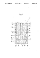
- FIG. 1 is a longitudinal cross sectional view of an igniter plug according to a first embodiment of the invention, but partly broken away;
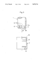
- FIG. 2 an exploded view of a metallic shell and a ground electrode
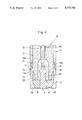
- FIG. 3 is a view similar to FIG. 1 according to a second embodiment of the invention.
- FIG. 4 is a prior igniter plug mounted on an internal combustion engine.
- denotation (A) designates an igniter plug, but partly broken away in FIG. 1.
- the igniter plug (A) has a tubular metallic shell 1 and an annular ground electrode 2 each connected in series by means of interfitting, and fixed at the connection between the shell 1 and the electrode 2 by means of welding as indicated at numeral 20.
- a tubular insulator 3 concentrically inserted with its inner space as an axial bore 31 into which a center electrode 4 is concentrically provided to be surrounded by the ground electrode 2.
- the metallic shell 1 is made of stainless steel, and having a male thread (not shown) at its outer surface for the purpose of mounting the igniter plug on an engine block.
- a front end 11 of the metallic shell 1 is diametrically reduced at a step portion 11a so that an outer diameter of the front end 11 is substantially equal to an inner diameter of the ground electrode 2.
- the front end 11 of the metallic shell 1 thus diametrically reduced, are twelve number of lock arms 13 provided by circumferentially notching axial slits 12 thereon with regular intervals.
- Each of the lock arms 13 has an integral pawl 13a at its top end.
- the ground electrode 2 is made from tungsten-based alloy which has an erosion-resistant property, and an outer diameter of the electrode 2 is generally equivalent to that of metallic shell 1.
- an inner surface of a rear end of the metallic shell 1 is a groove 21 circumferentially provided to be in registration with the pawl 13a of the lock arm 13.
- an inner surface of a front end of the metallic shell 1 has a taper surface 22, an inner diameter of which progressively decreases toward a front end of the ground electrode 2.
- the insulator is made of a sintered ceramic body with alumina as a main component. A thickness of a front end 32 of the insulator 3 is somewhat reduced so that an inner diameter of the insulator 3 is slightly greater than an outer diameter of the center electrode 4.
- annular semi-conductor tip 6 placed which has a rear surface 61 abutting against a front end 33 of the insulator 3, and at the same time, having an outer surface 62 seated on the taper surface 22.
- the center electrode 4 consist of a firing tip 41 made from tungsten-based alloy which is connected in series with a axial bar 42 made from nickel-based alloy by means of welding 43.
- the firing tip 41 extends from a front end of the axial bar 42, and passing through the axial bore 31 to be concentrically located within the semi-conductor tip 6.
- a glass sealant 51 filled when the glass sealant 51 is melt at a high temperature.
- the front end 11 of the metallic shell is machined by an engine lathe to reduce its outer diameter.
- the axial slits 12 provided to form the lock arms 13, each of which carries the pawl 13a at its top end.
- the number of the lock arms 13 is preferably within four to twenty. When the number of the lock arms decreases to three or less than three, the lock arms are unlikely to elastically flex. When the number of the lock arms exceeds to twenty, each width of the lock arms tends to diminish so as to be short of strength as a whole.
- the groove 21 is provided with the inner surface of the ground electrode 2.
- the metallic shell 1 interfits its front end 11 into the rear end of the ground electrode 2 as indicated by an arrow 53 so as to make the lock arms 13 elastically flex to bring the pawls 13a into an engagement with the inner wall of the groove 21.
- the step portion 11a of the metallic shell 1 butts on the rear end 2a of the ground electrode 2.
- the axial length of the pawl 13a is determined to be somewhat smaller than a width of the groove 21 so as to provide a space (p) which allows to absorb shrinkage after the metallic shell 1 and the ground electrode 2 are welded.
- the lock arms are brought the pawls into an engagement with the inner wall of the groove, while the insulator is brought into the engagement with the inner surface of the lock arm to block the electrode against separation from the metallic shell, thus capable of preventing a ground electrode from accidentally falling off a metallic shell to do damage to an engine even when a welding portion between the electrode and the shell is collapsed by an excessive oxidation so as to contribute to an extended period of service life, and achieving these effects with a relatively simple construction and less cost.
- FIG. 3 shows a second embodiment of the invention in which like reference numerals in FIG. 3 is identical to those in FIG. 1.
- the groove 21 is provided with an inner surface of the metallic shell 1, while the lock arms 13 are proided with a rear end of the ground electrode 2 in a manner similar to that mentioned in the first embodiment of the invention.
- Each pawl 13a formed on the lock arms 13 is brought into an engagement with the inner wall of the groove 21 when the metallic shell 1 is connected to the ground electrode 2.
- the step portion 11a of the ground electrode 2 abutts on a front end 1a of the metallic shell 1, and fixed by means of welding 20.
- the case mentioned in the second embodiment is particularly advantageous when the ground electrode 2 is anticipated to have an elastic property.
- the insulator 3 may be brought into an engagement with the inner surface of the lock arms 13 by way of the glass sealant 51, the semi-conductor tip 6 or a ring (not shown).
- portions in which the metallic shell 1 and the ground electrode 2 are interfit each other may be in the form of polygon to prevent relative rotation when the welding portion 20 is collapsed.
- connection between the metallic shell 1 and the ground electrode 2 is fixed by means of spot welding or electrical resistant welding, instead of the welding the metallic shell 1 and the ground electrode 2 may be fixed by means of brazing.
Landscapes
- Spark Plugs (AREA)
Abstract
An igniter plug has a tubular metallic shell and an annular ground electrode each connected in series by an interfitting, and fixed by welding. The igniter plug further has a tubular insulator placed within both the metallic shell and the ground electrode, while a center electrode is placed within the insulator to be surrounded by the ground electrode. A plurality of lock arms are provided with a front end of the metallic shell, and each top end of lock arms has a pawl which is brought into an engagement with an inner wall of a groove which is provided with an inner surface of the ground electrode when the metallic shell and the ground electrode are connected, and at the same time, the insulator is brought into an engagement with an inner side of each lock arm to deter the lock arms from being flexed inwardly when the insulator is placed.
Description
1. Field of the Invention
This invention relates to an igniter plug for use in an internal combustion engine, gas turbine engine, diesel engine, gas burner and oil burner, and particularly concerns to an igniter plug in which a metallic shell and a ground electrode are connected by means of interfitting.
2. Description of Prior Art
In an igniter plug (C) usually employed to an internal combustion engine 101, a metallic shell 100 and a ground electrode 200 are discretely made from stenless steel and tungsten in turn as seen in FIG. 4. The ground electrode 200 is connected in series with a front end 110 of the metallic shell 100 by means of interfitting, and the connection between the shell 100 and the electrode 200 is fixed by welding as indicated by numeral 300. Within the shell 100 and the electrode 200, a tubular insulator 400 is placed with its inner space as an axial bore 410 into which a center electrode 500 is inserted.
With a recent high-output performance of the internal combustion engine 101, the ambient temperature within a combustion chamber 600 tends to rise so that the welding portion 300 may collapse by an excessive oxidation to fall the ground electrode 200 off the metallic shell 100 so as to do a damage to the engine since the electrode 200 is simply interfit into the shell 100. For this reason, it has been required to prevent the ground electrode 200 from accidentally falling off the metallic shell 100.
Therefore, it is an object of the invention to provide an igniter plug which is capable of prevent a ground electrode from accidentally falling off a metallic shell even when a welding portion between the electrode and the shell is collapsed by an excessive oxidation so as to contribute to an extended period of service life, and achieving this effect with a relatively simple construction.
According to the invention, in an igniter plug comprising a tubular metallic shell and an annular ground electrode each connected in series by an interfitting, and fixed by means of welding or brazing, the igniter plug further having a tubular insulator concentrically placed within both the metallic shell and the ground electrode, while a center electrode is concentrically placed within the insulator to be surrounded by the ground electrode, there is provided an igniter plug having a plurality of lock arms circumferentially provided with either of a rear end of the ground electrode or a front end of the metallic shell by providing axial slits therewith, and each of the lock arms having a pawl at its top end; a groove circumferentially provided with an inner surface of the rest of the ground electrode or the metallic shell to be in registration with the pawls of the lock arms, whereby the lock arms elastically flexes to bring the pawls into an engagement with an inner wall of the groove when the metallic shell and the ground electrode are connected in series, and at the same time, the insulator is brought into an engagement with an inner side of each lock arm to deter the lock arms from being flexed inwardly when the insulator is placed.
At the time of connecting the ground electrode to the metallic shell, the lock arms engage the pawls with the inner wall of the groove, while the insulator is brought into the engagement with the inner surface of the lock arm to block the electrode against separation from the metallic shell, thus capable of preventing a ground electrode from accidentally falling off a metallic shell even when a welding portion between the electrode and the shell is collapsed by an excessive oxidation so as to contribute to an extended period of service life, and achieving these effects with a relatively simple construction.
These and other objects and advantages of the invention will be apparent upon reference to the following specification, attendant claims and drawings.
FIG. 1 is a longitudinal cross sectional view of an igniter plug according to a first embodiment of the invention, but partly broken away;
FIG. 2 an exploded view of a metallic shell and a ground electrode;
FIG. 3 is a view similar to FIG. 1 according to a second embodiment of the invention; and
FIG. 4 is a prior igniter plug mounted on an internal combustion engine.
Referring to FIG. 1 in which a first embodiment of the invention is shown, denotation (A) designates an igniter plug, but partly broken away in FIG. 1. The igniter plug (A) has a tubular metallic shell 1 and an annular ground electrode 2 each connected in series by means of interfitting, and fixed at the connection between the shell 1 and the electrode 2 by means of welding as indicated at numeral 20. Into both the metallic shell 1 and the electrode 2, is a tubular insulator 3 concentrically inserted with its inner space as an axial bore 31 into which a center electrode 4 is concentrically provided to be surrounded by the ground electrode 2. The metallic shell 1 is made of stainless steel, and having a male thread (not shown) at its outer surface for the purpose of mounting the igniter plug on an engine block. A front end 11 of the metallic shell 1 is diametrically reduced at a step portion 11a so that an outer diameter of the front end 11 is substantially equal to an inner diameter of the ground electrode 2. With the front end 11 of the metallic shell 1, thus diametrically reduced, are twelve number of lock arms 13 provided by circumferentially notching axial slits 12 thereon with regular intervals. Each of the lock arms 13 has an integral pawl 13a at its top end. The ground electrode 2 is made from tungsten-based alloy which has an erosion-resistant property, and an outer diameter of the electrode 2 is generally equivalent to that of metallic shell 1.
With an inner surface of a rear end of the metallic shell 1, is a groove 21 circumferentially provided to be in registration with the pawl 13a of the lock arm 13. On the other hand, an inner surface of a front end of the metallic shell 1 has a taper surface 22, an inner diameter of which progressively decreases toward a front end of the ground electrode 2. The insulator is made of a sintered ceramic body with alumina as a main component. A thickness of a front end 32 of the insulator 3 is somewhat reduced so that an inner diameter of the insulator 3 is slightly greater than an outer diameter of the center electrode 4. Within the front end of the electrode 2, is an annular semi-conductor tip 6 placed which has a rear surface 61 abutting against a front end 33 of the insulator 3, and at the same time, having an outer surface 62 seated on the taper surface 22.
In the meantime, the center electrode 4 consist of a firing tip 41 made from tungsten-based alloy which is connected in series with a axial bar 42 made from nickel-based alloy by means of welding 43. The firing tip 41 extends from a front end of the axial bar 42, and passing through the axial bore 31 to be concentrically located within the semi-conductor tip 6. In a clearance appeared among the ground electrode 2, the front end 32 of the insulator 3 and the insulator, is a glass sealant 51 filled when the glass sealant 51 is melt at a high temperature.
The following is a procedure to build the igniter plug (A) explained in reference to FIG. 2.
(1) The front end 11 of the metallic shell is machined by an engine lathe to reduce its outer diameter. With front end 11 of the metallic shell 1, are the axial slits 12 provided to form the lock arms 13, each of which carries the pawl 13a at its top end. The number of the lock arms 13 is preferably within four to twenty. When the number of the lock arms decreases to three or less than three, the lock arms are unlikely to elastically flex. When the number of the lock arms exceeds to twenty, each width of the lock arms tends to diminish so as to be short of strength as a whole.
(2) The groove 21 is provided with the inner surface of the ground electrode 2.
(3) The metallic shell 1 interfits its front end 11 into the rear end of the ground electrode 2 as indicated by an arrow 53 so as to make the lock arms 13 elastically flex to bring the pawls 13a into an engagement with the inner wall of the groove 21. At this time, the step portion 11a of the metallic shell 1 butts on the rear end 2a of the ground electrode 2. The axial length of the pawl 13a is determined to be somewhat smaller than a width of the groove 21 so as to provide a space (p) which allows to absorb shrinkage after the metallic shell 1 and the ground electrode 2 are welded.
(4) The portion in which the step portion 11a of the metallic shell 1 butts on the rear end 2a of the ground electrode 2 is welded as designated by numeral 20.
(5) The glass sealant 51 is filled, and at the same time, the semi-conductor tip 6 is placed within the ground electrode 2.
(6) The insulator 3, which carries the center electrode 4, is inserted into both the metallic shell 1 and the ground electrode 2 so as to be brought into an engagement with an inner surface of each lock arm 13, and thus deterring the lock arm from flexing inwardly.
As apparent from the foregoing description, the lock arms are brought the pawls into an engagement with the inner wall of the groove, while the insulator is brought into the engagement with the inner surface of the lock arm to block the electrode against separation from the metallic shell, thus capable of preventing a ground electrode from accidentally falling off a metallic shell to do damage to an engine even when a welding portion between the electrode and the shell is collapsed by an excessive oxidation so as to contribute to an extended period of service life, and achieving these effects with a relatively simple construction and less cost.
FIG. 3 shows a second embodiment of the invention in which like reference numerals in FIG. 3 is identical to those in FIG. 1. In an igniter plug (B) according to the second embodiment of the invention, the groove 21 is provided with an inner surface of the metallic shell 1, while the lock arms 13 are proided with a rear end of the ground electrode 2 in a manner similar to that mentioned in the first embodiment of the invention. Each pawl 13a formed on the lock arms 13 is brought into an engagement with the inner wall of the groove 21 when the metallic shell 1 is connected to the ground electrode 2. In accompany with this connection, the step portion 11a of the ground electrode 2 abutts on a front end 1a of the metallic shell 1, and fixed by means of welding 20. The case mentioned in the second embodiment is particularly advantageous when the ground electrode 2 is anticipated to have an elastic property.
It is noted that the insulator 3 may be brought into an engagement with the inner surface of the lock arms 13 by way of the glass sealant 51, the semi-conductor tip 6 or a ring (not shown).
It is appreciated that the portions in which the metallic shell 1 and the ground electrode 2 are interfit each other, may be in the form of polygon to prevent relative rotation when the welding portion 20 is collapsed.
It is further noted that the connection between the metallic shell 1 and the ground electrode 2 is fixed by means of spot welding or electrical resistant welding, instead of the welding the metallic shell 1 and the ground electrode 2 may be fixed by means of brazing.
While the invention has been described with reference to the specific embodiments, it is understood that this description is not to be construed in a limitting sense in as much as various modifications and additions to the specific embodiments may be made by skilled artisan without departing from the spirit and scope of the invention.
Claims (3)
1. In an igniter plug comprising a tubular metallic shell and an annular ground electrode each connected in series by an interfitting, and fixed by means of welding or brazing, the igniter plug further having a tubular insulator concentrically placed within both the metallic shell and the ground electrode, while a center electrode is concentrically placed within the insulator to be surrounded by the ground electrode;
the improvement comprising;
a plurality of lock arms circumferentially provided with either of a rear end of the ground electrode or a front end of the metallic shell by providing axial slits therewith, and each of the lock arms having a pawl at its top end;
a groove circumferentially provided with an inner surface of the rest of the ground electrode or the metallic shell to be in registration with the pawls of the lock arms, whereby the lock arms elastically flexes to bring the pawls into an engagement with an inner wall of the groove when the metallic shell and the ground electrode are connected in series, and at the same time, the insulator is brought into an engagement with an inner side of each lock arm to deter the lock arms from being flexed inwardly when the insulator is placed.
2. In an igniter plug as recited in claim 1, the lock arms are provided with a front end of the metallic shell, while the groove provided with an inner surface of the rear end of the ground electrode.
3. In an igniter plug as recited in claim 1, the lock arms are provided with a rear end of the ground electrode, while the groove provided with an inner surface of the front end of the metallic shell.
Applications Claiming Priority (2)
| Application Number | Priority Date | Filing Date | Title |
|---|---|---|---|
| JP1343693A JPH03205775A (en) | 1989-12-29 | 1989-12-29 | Ignitor plug |
| JP1-343693 | 1989-12-29 |
Publications (1)
| Publication Number | Publication Date |
|---|---|
| US5073741A true US5073741A (en) | 1991-12-17 |
Family
ID=18363523
Family Applications (1)
| Application Number | Title | Priority Date | Filing Date |
|---|---|---|---|
| US07/635,730 Expired - Lifetime US5073741A (en) | 1989-12-29 | 1990-12-28 | Igniter plug |
Country Status (4)
| Country | Link |
|---|---|
| US (1) | US5073741A (en) |
| JP (1) | JPH03205775A (en) |
| BR (1) | BR9006624A (en) |
| GB (1) | GB2239486B (en) |
Cited By (4)
| Publication number | Priority date | Publication date | Assignee | Title |
|---|---|---|---|---|
| US6561792B1 (en) | 2002-03-14 | 2003-05-13 | Albert G. Pfund | Adjustable electrode for oil burners |
| RU2285318C2 (en) * | 2004-12-14 | 2006-10-10 | Евгений Викторович Распопов | Spark plug for internal-combustion engines |
| US20070091542A1 (en) * | 2005-10-20 | 2007-04-26 | Denso Corporation | Spark plug and method of manufacturing same |
| RU2342811C1 (en) * | 2007-05-23 | 2008-12-27 | Федеральное государственное унитарное предприятие "Центральный институт авиационного моторостроения имени П.И. Баранова" | Method and device for initiation of vhf discharge and generation of high-temperature plasma stream (versions) |
Citations (3)
| Publication number | Priority date | Publication date | Assignee | Title |
|---|---|---|---|---|
| US965585A (en) * | 1908-11-04 | 1910-07-26 | Cyrus F Jones | Sparking plug for explosive-engines. |
| US3745400A (en) * | 1972-03-23 | 1973-07-10 | Bendix Corp | Igniter plug |
| US4952837A (en) * | 1988-05-09 | 1990-08-28 | Ngk Spark Plug Co., Ltd. | Surface gap type igniter plug |
Family Cites Families (3)
| Publication number | Priority date | Publication date | Assignee | Title |
|---|---|---|---|---|
| GB1004044A (en) * | 1963-07-19 | 1965-09-08 | British Aluminium Co Ltd | Improvements in or relating to connector pieces for tubular elements, tubular structures incorporating such connector pieces and methods of making such structures |
| US3330985A (en) * | 1965-11-08 | 1967-07-11 | Gen Motors Corp | High voltage igniter with fluid feed through the insulator core center |
| US3882338A (en) * | 1974-01-16 | 1975-05-06 | Bendix Corp | Igniter plug |
-
1989
- 1989-12-29 JP JP1343693A patent/JPH03205775A/en active Pending
-
1990
- 1990-12-19 BR BR909006624A patent/BR9006624A/en unknown
- 1990-12-28 US US07/635,730 patent/US5073741A/en not_active Expired - Lifetime
- 1990-12-31 GB GB9028207A patent/GB2239486B/en not_active Expired - Fee Related
Patent Citations (3)
| Publication number | Priority date | Publication date | Assignee | Title |
|---|---|---|---|---|
| US965585A (en) * | 1908-11-04 | 1910-07-26 | Cyrus F Jones | Sparking plug for explosive-engines. |
| US3745400A (en) * | 1972-03-23 | 1973-07-10 | Bendix Corp | Igniter plug |
| US4952837A (en) * | 1988-05-09 | 1990-08-28 | Ngk Spark Plug Co., Ltd. | Surface gap type igniter plug |
Cited By (4)
| Publication number | Priority date | Publication date | Assignee | Title |
|---|---|---|---|---|
| US6561792B1 (en) | 2002-03-14 | 2003-05-13 | Albert G. Pfund | Adjustable electrode for oil burners |
| RU2285318C2 (en) * | 2004-12-14 | 2006-10-10 | Евгений Викторович Распопов | Spark plug for internal-combustion engines |
| US20070091542A1 (en) * | 2005-10-20 | 2007-04-26 | Denso Corporation | Spark plug and method of manufacturing same |
| RU2342811C1 (en) * | 2007-05-23 | 2008-12-27 | Федеральное государственное унитарное предприятие "Центральный институт авиационного моторостроения имени П.И. Баранова" | Method and device for initiation of vhf discharge and generation of high-temperature plasma stream (versions) |
Also Published As
| Publication number | Publication date |
|---|---|
| GB9028207D0 (en) | 1991-02-13 |
| GB2239486A (en) | 1991-07-03 |
| GB2239486B (en) | 1994-01-12 |
| JPH03205775A (en) | 1991-09-09 |
| BR9006624A (en) | 1991-10-01 |
Similar Documents
| Publication | Publication Date | Title |
|---|---|---|
| US11545816B2 (en) | Spark plug with multiple spark gaps | |
| EP2139081B1 (en) | Spark plug and internal combustion engine with spark plug | |
| US6724132B2 (en) | Spark plug for an engine for a cogeneration system | |
| US5918571A (en) | Dual electrode high thread spark plug | |
| US4771209A (en) | Spark igniter having precious metal ground electrode inserts | |
| WO2021111719A1 (en) | Spark plug | |
| JP2000243535A (en) | Spark plug | |
| US7408293B2 (en) | Spark plug including ground elcetrode carrier casing | |
| WO2021041179A1 (en) | Spark plug ground electrode configuration | |
| US5073741A (en) | Igniter plug | |
| US7049733B2 (en) | Spark plug center electrode assembly | |
| EP0341807B1 (en) | A spark plug | |
| US11757262B1 (en) | Prechamber spark plug and method of manufacturing the same | |
| JP6611769B2 (en) | Spark plug | |
| JP7186044B2 (en) | Spark plug for internal combustion engine | |
| EP1444760B1 (en) | Spark plug | |
| GB2060773A (en) | Spark igniter | |
| US3056899A (en) | Spark plug adapter | |
| US4315298A (en) | Igniter plug | |
| CA1158499A (en) | Igniter plug | |
| US6048196A (en) | Durable self-grounding igniter for industrial burners | |
| JPH01274374A (en) | Drawing-in gap type ignitor plug | |
| JP6739482B2 (en) | Spark plug | |
| US11476644B2 (en) | Spark plug | |
| JPH06176848A (en) | Spark plug that prevents fouling |
Legal Events
| Date | Code | Title | Description |
|---|---|---|---|
| AS | Assignment |
Owner name: NGK SPARK PLUG CO., LTD., 14-BAN, 18-GOU, TAKATSUJ Free format text: ASSIGNMENT OF ASSIGNORS INTEREST.;ASSIGNORS:SUZUKI, TAKAHIRO;AOKI, NOBORU;REEL/FRAME:005574/0030 Effective date: 19901203 |
|
| STCF | Information on status: patent grant |
Free format text: PATENTED CASE |
|
| FEPP | Fee payment procedure |
Free format text: PAYOR NUMBER ASSIGNED (ORIGINAL EVENT CODE: ASPN); ENTITY STATUS OF PATENT OWNER: LARGE ENTITY |
|
| FPAY | Fee payment |
Year of fee payment: 4 |
|
| FPAY | Fee payment |
Year of fee payment: 8 |
|
| FPAY | Fee payment |
Year of fee payment: 12 |
|
| REMI | Maintenance fee reminder mailed |