US5066027A - Sealing ring apparatus - Google Patents
Sealing ring apparatus Download PDFInfo
- Publication number
- US5066027A US5066027A US07/547,374 US54737490A US5066027A US 5066027 A US5066027 A US 5066027A US 54737490 A US54737490 A US 54737490A US 5066027 A US5066027 A US 5066027A
- Authority
- US
- United States
- Prior art keywords
- sealing ring
- sealing
- groove
- ring
- machine part
- Prior art date
- Legal status (The legal status is an assumption and is not a legal conclusion. Google has not performed a legal analysis and makes no representation as to the accuracy of the status listed.)
- Expired - Fee Related
Links
Images

Classifications
-
- F—MECHANICAL ENGINEERING; LIGHTING; HEATING; WEAPONS; BLASTING
- F16—ENGINEERING ELEMENTS AND UNITS; GENERAL MEASURES FOR PRODUCING AND MAINTAINING EFFECTIVE FUNCTIONING OF MACHINES OR INSTALLATIONS; THERMAL INSULATION IN GENERAL
- F16J—PISTONS; CYLINDERS; SEALINGS
- F16J15/00—Sealings
- F16J15/16—Sealings between relatively-moving surfaces
- F16J15/32—Sealings between relatively-moving surfaces with elastic sealings, e.g. O-rings
Definitions
- the present invention relates to a structure for sealing the gap between two concentric machine parts which are arranged to move relative to each other, the first machine part being provided with a groove while the second one comprises a plain contact surface arranged opposite the said groove, the sealing ring structure comprising a sealing ring made of a tough-elastic plastic material and fitted in the groove of the first machine part, with a circumferential surface of the said sealing ring facing the contact surface being provided with an annular recess so that the sealing ring bears upon the contact surface of the second machine part by sealing edges arranged near its ends, and comprising further a stressing ring of a rubber-elastic material arranged between the sealing ring and the bottom of the groove and loading the sealing ring in the radial direction, the axial cross sectional length of the said stressing ring being smaller than that of the sealing ring, and its axial position being fixed, relative to the sealing ring, in such a manner that it occupies a substantially central position between the two sealing edges.
- a sealing ring structure of this type has been known from DE-PS 36 13 880.
- the groove of the one machine part accommodating the sealing ring and the stressing ring is provided in its central area with a recess which is engaged by the stressing ring so that the axial position of the stressing ring is fixed by this recess while the axial position of the sealing ring is fixed by the groove.
- the production of a groove which is provided with a recess in its central area requires a considerably increased input of labor during manufacture of the sealing ring structure.
- such a design makes it impossible to use such a sealing ring structure in place of other sealing ring structures whose grooves intended to accommodate the sealing rings do not comprise any such recess.
- supporting bodies in the groove of conventional sealing ring structures, for supporting the stressing ring laterally this would increase substantially the complexity of such a sealing ring structure.
- the known seal belongs to the type comprising sealing edges arranged in series, which become active in operation so that the function is similar to that of a tandem seal. Consequently, certain quantities of the highly pressurized fluid which is to be sealed off, which may pass the sealing edge at the high-pressure side may gather in the space between the two sealing edges. In this manner, a considerable pressure rise may occur in the space between the two sealing edges, with the result that the sealing edges may be lifted off the contact surface of the second machine part, and a certain leakage may occur.
- the solution to interconnect the space between two sealing edges of the sealing ring with that side of the sealing ring which is in contact with the stressing ring, by a radial channel has to be regarded as state of the prior art since the publication of patent application No.
- the stressing ring of the sealing ring structure described by patent application No. P 36 20 539.7 exhibits substantially the same axial length as the sealing ring, and the channel ends at a point near the high-pressure edge of the surface where the stressing ring is in contact with the sealing ring.
- the sealing ring comprises, at its surface facing the bottom of the groove, an annular groove of substantially trapezoidal cross-section accommodating the stressing ring which is in sealing contact with its inclined flanks, at least in the unpressurized condition, and further at least one radial bore interconnecting the recess between the sealing edges and the bottom of the annular groove.
- the stressing ring is fixed relative to the sealing ring by a groove provided in the circumferential surface of the sealing ring and exhibiting a substantially trapezoidal cross-section.
- the radial bores interconnecting the space between the sealing edges and that side of the sealing ring which is loaded by the stressing ring end at the bottom of the annular groove and accordingly, when no load is applied, at a central point relative to the stressing ring loading the sealing ring.
- the stressing ring is deformed to a certain degree towards the low-pressure side, under the action of the pressure of the fluid to be sealed off, whereby the contact pressure exerted by the stressing ring upon the flank of the annular groove on the low-pressure side rises, while the contact pressure is reduced at the flank of the annular groove on the high-pressure side, so that the stressing ring is lifted off the flank of the groove on the high-pressure side when the pressure of the fluid present in the space defined by the sealing edges exceeds a predetermined amount, and the excessively pressurized fluid is then permitted to escape towards the high-pressure side so that no leakage will occur.
- the particular advantage of the sealing ring structure according to the invention is seen for one thing in the fact that its structure is substantially simplified because no additional recess has to be worked into the groove for accommodating the rings so that the rings may be inserted into the groove of any usual sealing ring structure, and that the arrangement of the radial bores in conjunction with the stressing ring provides sort of a pressure-relief valve for relieving the annular space between the two sealing edges of the sealing ring.
- it is a particular additional advantage of this sealing ring structure that when a symmetrical design is used for the sealing ring it acts in both directions, i.e. independently of the side on which the pressurized fluid acts upon the sealing ring structure.
- sealing ring structure of this type can be used with particular advantage in all cases where the prevailing operating conditions may lead to changes in the direction from which the pressurized fluid acts upon the seal.
- the sealing ring may be given different cross-sections to adapt it optimally to the respective application.
- at least one of the sealing edges may be formed by the edge of the circumferential surface of an annular web provided at the end of the sealing ring, a design which has already been employed by the sealing ring structure of DE-PS 36 13 880 mentioned at the outset.
- the circumferential surface of the web may again form with the contact surface of the second machine part a small angle opening in the direction of the neighboring end face of the sealing ring.
- small angle as used herein is meant to describe angles of up to approx. 10°.
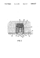
- FIG. 1 shows a cross sectional view of the sealing ring structure
- FIG. 2 shows a cross sectional view of a modified sealing ring structure with a small angle opening on the face of the sealing ring.
- FIG. 1 shows a sealing ring structure where a symmetrically designed sealing ring 53 is arranged in the groove 51 of a first component 52.
- the sealing ring 53 consists of a tough-elastic plastic material, and its inner circumferential surface rests against the contact surface 55 of a second machine part 56.
- the inner circumferential surface of the sealing ring 53 is provided with an annular recess so that each of the two ends of the sealing ring exhibits a web 61 or 62 and defining each a sealing edge 57, 58, respectively.
- the two sealing edges define between them the space 71 formed by the annular recess and intended to accommodate a fluid that may gather therein.
- the space 71 communicates with the opposite side of the sealing ring 53 via at least one radial bore 67.
- the radial bore 67 ends at the bottom of an annular groove of trapezoidal cross-section which is defined by flanks 64, 65 rising from the bottom of this groove.
- the described annular groove accommodates a stressing ring 54 of a rubber-elastic material, which is held in place in the first component between the sealing ring 53 and the bottom 63 of the groove 51.
- the arrangement illustrated by way of example exhibits a fully symmetrical design. Accordingly, it is active irrespective of the side from which the pressurized fluid, which is to be sealed off, acts upon the arrangement. If, for example, the pressurized fluid is present on the left side of the sealing ring structure--as viewed in the drawing--then the pressure exerted upon the sealing ring 53 acts upon the right flank 65 of the groove 51, and the stressing ring 54 is also deformed a little towards the right, whereby the contact pressure prevailing at the left flank 64 of the annular groove in the sealing ring 53, at the high-pressure side, and also the force required for lifting the stressing ring 54 off the ends of the radial bore 57, is reduced.
- any pressure fluid that may have been dragged into the space 71 may escape towards the high-pressure side, through the radial bore 67 and along the flank 64 of the annular groove, once a predetermined overpressure is exceeded, because the contact pressure exerted by the stressing ring 54 upon this flank 64 at the high-pressure side is considerably lower than that exerted upon the opposite flank 65 on the low-pressure side.
- the sealing ring structure obtained is of the type acting in both directions which can be used with particular advantage for sealing off against each other two spaces in which the pressure alternates frequently so that the overpressure prevails in the one instance in the right and in the other instance in the left space.
- Working spaces of this type which have to be sealed off relative to each other are encountered very often in working machines using hydraulic drive.
- the invention is not restricted to the embodiments illustrated in FIG. 2.
- the webs 61, 62 provided at the ends of the sealing ring 53 may comprise circumferential surfaces forming with the contact surface of the second machine part a small angle opening towards the neighboring end face of the ring.
- Such an angle which should not be greater than 10°, need not necessarily exist already in the unstressed condition of the stressing, but may result from the sealing ring bending slightly under the action of the force of the stressing ring.
- the sealing ring structure according to the invention is suited not only for sealing off parts reciprocating in the axial direction of the sealing ring structure, i.e. for sealing in particular the gap between piston rods and their housings.
Landscapes
- Engineering & Computer Science (AREA)
- General Engineering & Computer Science (AREA)
- Mechanical Engineering (AREA)
- Sealing Devices (AREA)
- Glass Compositions (AREA)
- Sealing Battery Cases Or Jackets (AREA)
- Separation By Low-Temperature Treatments (AREA)
- Processing Of Stones Or Stones Resemblance Materials (AREA)
- Gasket Seals (AREA)
- Sealing With Elastic Sealing Lips (AREA)
Applications Claiming Priority (2)
| Application Number | Priority Date | Filing Date | Title |
|---|---|---|---|
| DE3743726 | 1987-12-23 | ||
| DE3743726A DE3743726C1 (de) | 1987-12-23 | 1987-12-23 | Dichtungsanordnung |
Related Parent Applications (1)
| Application Number | Title | Priority Date | Filing Date |
|---|---|---|---|
| US07285785 Continuation | 1988-12-16 |
Publications (1)
| Publication Number | Publication Date |
|---|---|
| US5066027A true US5066027A (en) | 1991-11-19 |
Family
ID=6343372
Family Applications (1)
| Application Number | Title | Priority Date | Filing Date |
|---|---|---|---|
| US07/547,374 Expired - Fee Related US5066027A (en) | 1987-12-23 | 1990-07-03 | Sealing ring apparatus |
Country Status (7)
| Country | Link |
|---|---|
| US (1) | US5066027A (de) |
| EP (1) | EP0321770B1 (de) |
| JP (1) | JP2523006B2 (de) |
| AT (1) | ATE85842T1 (de) |
| DE (2) | DE3743726C1 (de) |
| DK (1) | DK165927C (de) |
| ES (1) | ES2039574T3 (de) |
Cited By (13)
| Publication number | Priority date | Publication date | Assignee | Title |
|---|---|---|---|---|
| US5332236A (en) * | 1991-08-26 | 1994-07-26 | Sumitomo Precision Products, Co., Ltd. | Sealing mechanism for a rotary actuator |
| US5755446A (en) * | 1996-12-24 | 1998-05-26 | United Technologies Corporation | Seal apparatus between a shaft and a non-linear inner surface of a housing |
| US20050249608A1 (en) * | 2004-05-10 | 2005-11-10 | Shinji Tagami | Inclined plate-type compressors and air conditioning systems including such compressors |
| US7083170B2 (en) * | 2001-04-09 | 2006-08-01 | Carl Freudenberg Kg | Rod or piston primary seal |
| WO2008141388A1 (en) * | 2007-05-22 | 2008-11-27 | Simmons Group Investments Pty Ltd | Sealed joint assembly |
| US20090108542A1 (en) * | 2006-05-16 | 2009-04-30 | Semiconductor Energy Laboratory Co., Ltd | Seal Assembly for Relieving Pressure |
| US20110012312A1 (en) * | 2008-03-10 | 2011-01-20 | Skf Polyseal Inc. | Pressure regulating seal |
| CN102705259A (zh) * | 2012-05-25 | 2012-10-03 | 南京长江涂料有限公司 | 填料密封装置 |
| US20120292858A1 (en) * | 2010-01-28 | 2012-11-22 | Holger Jordan | Rotary seal arrangement |
| US20130213219A1 (en) * | 2012-02-17 | 2013-08-22 | Federal-Mogul Corporation | Piston ring for an internal combustion engine |
| CN105308370A (zh) * | 2013-06-03 | 2016-02-03 | Nok株式会社 | 密封环 |
| US20160076651A1 (en) * | 2014-09-12 | 2016-03-17 | Trelleborg Sealing Solutions Us, Inc. | Rotary hydraulic actuator seal |
| US20170211703A1 (en) * | 2014-05-29 | 2017-07-27 | Nok Corporation | Sealing structure and sealing device |
Families Citing this family (5)
| Publication number | Priority date | Publication date | Assignee | Title |
|---|---|---|---|---|
| DE4017036C2 (de) * | 1990-05-26 | 1994-01-27 | Busak & Luyken Gmbh & Co | Dichtungsanordnung |
| US6036191A (en) * | 1991-01-16 | 2000-03-14 | Adwest Engineering Limited | Rotary valve seal assembly |
| GB9100903D0 (en) * | 1991-01-16 | 1991-02-27 | Adwest Eng Ltd | Rotary valve seal assembly |
| DE4140833C3 (de) * | 1991-04-30 | 1995-03-16 | Busak & Luyken Gmbh & Co | Dichtungsanordnung |
| JP5545420B1 (ja) * | 2012-08-21 | 2014-07-09 | Nok株式会社 | シールリング |
Citations (13)
| Publication number | Priority date | Publication date | Assignee | Title |
|---|---|---|---|---|
| US2631907A (en) * | 1947-11-28 | 1953-03-17 | Ohio Brass Co | Valve |
| US2937061A (en) * | 1958-03-31 | 1960-05-17 | Chrysler Corp | Sealing device |
| US3109661A (en) * | 1962-01-10 | 1963-11-05 | Frank H Swaim | Low torque rotary seal |
| US3418001A (en) * | 1967-11-01 | 1968-12-24 | Minnesota Rubber Co | Fluid seal |
| US4331065A (en) * | 1979-10-18 | 1982-05-25 | General Motors Corporation | Engine piston assembly with improved oil control |
| US4523765A (en) * | 1983-06-07 | 1985-06-18 | Norton Christensen, Inc. | High pressure sealing means for longitudinally movable parts of deep-well drilling tools |
| US4681327A (en) * | 1985-11-25 | 1987-07-21 | Societe Nationale D'etude Et De Construction De Moteurs D'aviation "S.N.E.C.M.A." | Compound seal with pressure equalization aperture |
| US4702482A (en) * | 1985-06-29 | 1987-10-27 | Dowty Seals Limited | Sealing assembly with elastomeric energizing means |
| US4709932A (en) * | 1986-02-06 | 1987-12-01 | Busak & Luyken Gmbh And Co. | Double wiper seal arrangement |
| US4714259A (en) * | 1986-04-24 | 1987-12-22 | Busak + Luyken Gmbh & Co. | Sealing ring structure with stressing ring |
| US4723782A (en) * | 1986-06-19 | 1988-02-09 | Busak + Luyken Gmbh & Co. | Arrangement for sealing a rod |
| US4749201A (en) * | 1984-11-27 | 1988-06-07 | Walter Hunger | Sealing unit and a process for sealing parts |
| US4953876A (en) * | 1987-11-17 | 1990-09-04 | Busak & Luyken Gmbh & Co. | Sealing ring structure |
Family Cites Families (5)
| Publication number | Priority date | Publication date | Assignee | Title |
|---|---|---|---|---|
| US2528895A (en) * | 1945-10-30 | 1950-11-07 | Pelton Water Wheel Co | Seal ring |
| DE1940698A1 (de) * | 1968-08-21 | 1970-11-26 | Shamban & Co W S | Dichtungsanordnung |
| US3614114A (en) * | 1969-07-14 | 1971-10-19 | Shamban & Co W S | Seal assembly |
| DE3207327A1 (de) * | 1982-03-01 | 1983-09-08 | Heinz Konrad Prof. Dr.-Ing. 7050 Waiblingen Müller | Wellendichtung |
| DE8709644U1 (de) * | 1986-08-01 | 1987-09-24 | Heute & Co, 5608 Radevormwald, De |
-
1987
- 1987-12-23 DE DE3743726A patent/DE3743726C1/de not_active Expired
-
1988
- 1988-12-05 AT AT88120287T patent/ATE85842T1/de not_active IP Right Cessation
- 1988-12-05 EP EP88120287A patent/EP0321770B1/de not_active Expired - Lifetime
- 1988-12-05 ES ES198888120287T patent/ES2039574T3/es not_active Expired - Lifetime
- 1988-12-05 DE DE8888120287T patent/DE3878545D1/de not_active Expired - Fee Related
- 1988-12-20 DK DK706988A patent/DK165927C/da not_active IP Right Cessation
- 1988-12-23 JP JP63327523A patent/JP2523006B2/ja not_active Expired - Lifetime
-
1990
- 1990-07-03 US US07/547,374 patent/US5066027A/en not_active Expired - Fee Related
Patent Citations (13)
| Publication number | Priority date | Publication date | Assignee | Title |
|---|---|---|---|---|
| US2631907A (en) * | 1947-11-28 | 1953-03-17 | Ohio Brass Co | Valve |
| US2937061A (en) * | 1958-03-31 | 1960-05-17 | Chrysler Corp | Sealing device |
| US3109661A (en) * | 1962-01-10 | 1963-11-05 | Frank H Swaim | Low torque rotary seal |
| US3418001A (en) * | 1967-11-01 | 1968-12-24 | Minnesota Rubber Co | Fluid seal |
| US4331065A (en) * | 1979-10-18 | 1982-05-25 | General Motors Corporation | Engine piston assembly with improved oil control |
| US4523765A (en) * | 1983-06-07 | 1985-06-18 | Norton Christensen, Inc. | High pressure sealing means for longitudinally movable parts of deep-well drilling tools |
| US4749201A (en) * | 1984-11-27 | 1988-06-07 | Walter Hunger | Sealing unit and a process for sealing parts |
| US4702482A (en) * | 1985-06-29 | 1987-10-27 | Dowty Seals Limited | Sealing assembly with elastomeric energizing means |
| US4681327A (en) * | 1985-11-25 | 1987-07-21 | Societe Nationale D'etude Et De Construction De Moteurs D'aviation "S.N.E.C.M.A." | Compound seal with pressure equalization aperture |
| US4709932A (en) * | 1986-02-06 | 1987-12-01 | Busak & Luyken Gmbh And Co. | Double wiper seal arrangement |
| US4714259A (en) * | 1986-04-24 | 1987-12-22 | Busak + Luyken Gmbh & Co. | Sealing ring structure with stressing ring |
| US4723782A (en) * | 1986-06-19 | 1988-02-09 | Busak + Luyken Gmbh & Co. | Arrangement for sealing a rod |
| US4953876A (en) * | 1987-11-17 | 1990-09-04 | Busak & Luyken Gmbh & Co. | Sealing ring structure |
Cited By (19)
| Publication number | Priority date | Publication date | Assignee | Title |
|---|---|---|---|---|
| US5332236A (en) * | 1991-08-26 | 1994-07-26 | Sumitomo Precision Products, Co., Ltd. | Sealing mechanism for a rotary actuator |
| US5755446A (en) * | 1996-12-24 | 1998-05-26 | United Technologies Corporation | Seal apparatus between a shaft and a non-linear inner surface of a housing |
| US7083170B2 (en) * | 2001-04-09 | 2006-08-01 | Carl Freudenberg Kg | Rod or piston primary seal |
| US7632077B2 (en) * | 2004-05-10 | 2009-12-15 | Sanden Corporation | Inclined plate-type compressors and air conditioning systems including such compressors |
| US20050249608A1 (en) * | 2004-05-10 | 2005-11-10 | Shinji Tagami | Inclined plate-type compressors and air conditioning systems including such compressors |
| US20090108542A1 (en) * | 2006-05-16 | 2009-04-30 | Semiconductor Energy Laboratory Co., Ltd | Seal Assembly for Relieving Pressure |
| WO2008141388A1 (en) * | 2007-05-22 | 2008-11-27 | Simmons Group Investments Pty Ltd | Sealed joint assembly |
| US20110012312A1 (en) * | 2008-03-10 | 2011-01-20 | Skf Polyseal Inc. | Pressure regulating seal |
| US20170097093A1 (en) * | 2010-01-28 | 2017-04-06 | Trelleborg Sealing Solutions Germany Gmbh | Rotary sealing arrangement |
| US20120292858A1 (en) * | 2010-01-28 | 2012-11-22 | Holger Jordan | Rotary seal arrangement |
| US10508740B2 (en) * | 2010-01-28 | 2019-12-17 | Trelleborg Sealing Solutions Germany Gmbh | Rotary sealing arrangement |
| US20130213219A1 (en) * | 2012-02-17 | 2013-08-22 | Federal-Mogul Corporation | Piston ring for an internal combustion engine |
| US10125869B2 (en) * | 2012-02-17 | 2018-11-13 | Tenneco Inc. | Piston ring for an internal combustion engine |
| CN102705259A (zh) * | 2012-05-25 | 2012-10-03 | 南京长江涂料有限公司 | 填料密封装置 |
| CN105308370A (zh) * | 2013-06-03 | 2016-02-03 | Nok株式会社 | 密封环 |
| US10634254B2 (en) | 2013-06-03 | 2020-04-28 | Nok Corporation | Seal ring |
| US20170211703A1 (en) * | 2014-05-29 | 2017-07-27 | Nok Corporation | Sealing structure and sealing device |
| US20160076651A1 (en) * | 2014-09-12 | 2016-03-17 | Trelleborg Sealing Solutions Us, Inc. | Rotary hydraulic actuator seal |
| US10202989B2 (en) * | 2014-09-12 | 2019-02-12 | Trelleborg Sealing Solutions Us, Inc. | Rotary hydraulic actuator seal |
Also Published As
| Publication number | Publication date |
|---|---|
| JPH01203766A (ja) | 1989-08-16 |
| DE3743726C1 (de) | 1989-04-27 |
| DK706988A (da) | 1989-06-24 |
| EP0321770A1 (de) | 1989-06-28 |
| DK706988D0 (da) | 1988-12-20 |
| DK165927B (da) | 1993-02-08 |
| DE3878545D1 (de) | 1993-03-25 |
| ES2039574T3 (es) | 1993-10-01 |
| JP2523006B2 (ja) | 1996-08-07 |
| DK165927C (da) | 1993-07-05 |
| ATE85842T1 (de) | 1993-03-15 |
| EP0321770B1 (de) | 1993-02-17 |
Similar Documents
| Publication | Publication Date | Title |
|---|---|---|
| US5066027A (en) | Sealing ring apparatus | |
| US4953876A (en) | Sealing ring structure | |
| KR20000035412A (ko) | 제어 티핑에 적합한 여유각을 구비한 회전 밀봉제 | |
| US5172921A (en) | Sealing device | |
| EP0207703B1 (de) | Dichtungsanordnung | |
| US3909016A (en) | Seal assembly with pivotable slipper seal | |
| EP0466076A2 (de) | Spiralrillengleitringdichtung | |
| EP2423539B1 (de) | Dichtungsanordnung | |
| EP0424372B1 (de) | Kombinationsdichtungsring zur abdichtung von zwei maschinenteilen | |
| EP2551563A1 (de) | Dichtung für eine drehwelle | |
| US4911455A (en) | Sealing ring structure | |
| EP0221585B1 (de) | Endabdichtungsringzusammenbau | |
| US4089253A (en) | Linear fluid motor | |
| EP0410074B1 (de) | Anlage zum Verringern von Radialbelastung und diese umfassende Gleitlager und Schraubenverdichter | |
| US7478815B2 (en) | High-pressure sealing assembly | |
| CH640322A5 (de) | Dichtungseinrichtung. | |
| US4336006A (en) | Gear positive displacement machine with gaps between bearing members and housing | |
| SK279923B6 (sk) | Gumový elastický tesniaci prstenec | |
| KR100594821B1 (ko) | 볼 밸브용 환상형 씰 | |
| US4709629A (en) | Roll with pressure chamber for detection control | |
| DE2126827A1 (en) | Ptfe gasket ring - for fixed and/or moving machine parts in pressurized or evacuated zones | |
| EP0030085B1 (de) | Stirnflächen-Druckdichtung für Gleiskettengelenke | |
| KR950008820B1 (ko) | 밀봉장치 | |
| US20230341055A1 (en) | Seal arrangement with low drag seal gland | |
| US5127660A (en) | Support mechanism for fluid film seals |
Legal Events
| Date | Code | Title | Description |
|---|---|---|---|
| FEPP | Fee payment procedure |
Free format text: PAT HLDR NO LONGER CLAIMS SMALL ENT STAT AS INDIV INVENTOR (ORIGINAL EVENT CODE: LSM1); ENTITY STATUS OF PATENT OWNER: LARGE ENTITY |
|
| FEPP | Fee payment procedure |
Free format text: PAYOR NUMBER ASSIGNED (ORIGINAL EVENT CODE: ASPN); ENTITY STATUS OF PATENT OWNER: LARGE ENTITY |
|
| FPAY | Fee payment |
Year of fee payment: 4 |
|
| REMI | Maintenance fee reminder mailed | ||
| LAPS | Lapse for failure to pay maintenance fees | ||
| FP | Lapsed due to failure to pay maintenance fee |
Effective date: 19991119 |
|
| STCH | Information on status: patent discontinuation |
Free format text: PATENT EXPIRED DUE TO NONPAYMENT OF MAINTENANCE FEES UNDER 37 CFR 1.362 |