US5051916A - Stimulus signal generation method to maximize dynamic range in frequency response function calculations - Google Patents
Stimulus signal generation method to maximize dynamic range in frequency response function calculations Download PDFInfo
- Publication number
- US5051916A US5051916A US07/464,486 US46448690A US5051916A US 5051916 A US5051916 A US 5051916A US 46448690 A US46448690 A US 46448690A US 5051916 A US5051916 A US 5051916A
- Authority
- US
- United States
- Prior art keywords
- stimulus
- spectrum
- frequency response
- response function
- signal
- Prior art date
- Legal status (The legal status is an assumption and is not a legal conclusion. Google has not performed a legal analysis and makes no representation as to the accuracy of the status listed.)
- Expired - Lifetime
Links
Images
Classifications
-
- G—PHYSICS
- G01—MEASURING; TESTING
- G01R—MEASURING ELECTRIC VARIABLES; MEASURING MAGNETIC VARIABLES
- G01R23/00—Arrangements for measuring frequencies; Arrangements for analysing frequency spectra
- G01R23/16—Spectrum analysis; Fourier analysis
Definitions
- This invention relates to the field of frequency response function calculation, and more particularly to the field of stimulus signal generation for frequency response function calculations with maximum dynamic range.
- a frequency response function describes the relationship between the input and output of a physical system.
- the system involved can be either mechanical, electrical, or some other type of linear physical system. To characterize such systems, it desirable to be able to accurately calculate their frequency response function, which in most cases is a very close approximation of the actual transfer function of the system.
- the frequency response function is complex, since for each frequency component of the input to the system, there is both a magnitude value and phase value to the system's response.
- a function, x(t), describes the magnitude of the stimulus signal to the system as a function of time.
- the Fourier transform function, X(f), of the stimulus signal, x(t), describes the magnitude and phase content of the stimulus signal as a function of frequency.
- another function, y(t), describes the magnitude of the output from the system as a function of time.
- Y(f) that describes the magnitude and phase of the output signal, y(t), as a function of frequency.
- the corresponding Fourier Transforms, X(f) and Y(f) can be calculated using a Fast Fourier Transform (FFT) algorithm or other similar method.
- FFT Fast Fourier Transform
- the frequency response function, H(f) can be calculated according to the following relationship: ##EQU1## where, Cspec(X,Y) is the cross power spectrum between X(f) and Y(f), Aspec(X) is the auto power spectrum of Y(f), and H(f) is the frequency response function of the system, which in most cases is a good estimation of the actual transfer function of the system, H(f).
- Modern instruments such as the 2642 Personal Fourier Analyzer made by Tektronix, Inc., Beaverton, Oreg., provide a means for supplying stimulus to a system and measuring its response.
- the computational facilities and other capabilities of this instrument are described in the 2641/2642 Fourier Analyzer User's Guide and the 2641/2642 Fourier Analyzer TurboPac Application Library, both of which are hereby incorporated by reference.
- the dynamic range of a channel refers to the overall ability of the instrument to distinguish between real signals and those artifacts and distortions that inevitably occur during measurement and computation. These include such factors as the non-linearity of analog components and A/D converters, signal leakage through power supplies and logic signals, jitter in the sampling clock, aliasing products, and truncation and other errors in the arithmetic associated with digital filtering, FFT computations, and averaging operations.
- the dynamic range specification for the 2642 Personal Fourier Analyzer is 75 dB. This means that if a known-to-be-pure full-scale sine wave is applied to one of the inputs of the Analyzer, all of the associated spectral artifacts will be below the full scale by at least 75 dB. But, no matter how good the dynamic range of the input channels may be, there is still always some such limit.
- One of the original methods of characterizing the frequency response function of a system under analysis is to provide a pure sinusoidal signal at one frequency at the input, and then to measure the output of the system at that frequency at the output. By slowly varying the frequency, and measuring the system output at each frequency, the system can eventually be characterized for all frequencies of interest. This approach requires a lot of time, but does not require a lot of dynamic range on the input and output channels, since the settings of the input and output channels can be varied from frequency to frequency as the sweeping of the bandwidth of interest occurs.
- What is desired is a method for generating a stimulus signal for conducting frequency response function calculations that maximizes the overall dynamic range of the calculations possible by balancing the requirements for dynamic range between the two analyzer channels being used to make the calculation.
- the present invention is a method for generating a stimulus signal for conducting frequency response and other similar stimulus response function calculations that maximizes the overall dynamic range of the calculations possible by balancing the requirements for dynamic range between the analyzer channels monitoring the input and output of the system under analysis.
- This method includes the steps of estimating the frequency response function of the system under analysis, inverting the estimated frequency response function, taking the square root of the inverted estimated frequency response function, randomizing the phase of the inverse square-root estimated frequency response function, converting the phase-randomized inverse square-root estimated frequency response function to a time domain test signal, scaling the time domain test signal as necessary to produce a stimulus signal for conducting frequency response function calculations that allocates the requirement for amplitude dynamic range between the two signal analyzers channels used to monitor the stimulus signal and the output signal of the system under analysis.
- the method can be repeated using the improved estimate of the frequency response function from one calculation as the starting point for the next iteration.
- a the method is repeated and increasingly accurate results are obtained, the cross power spectrum taken between the stimulus signal and the output signal will ideally converge toward a flat profile within a few iterations.
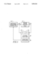
- FIG. 1 is a block diagram of the test setup used to practice the present invention.
- FIG. 2 is a logic flow diagram of the procedure used to practice the present invention.
- an arbitrary waveform generator 10 produces a time-varying stimulus signal, x(t), having a frequency domain representation X(f).
- This stimulus signal, x(t) is applied to the input of system under analysis 12 having a frequency response function H(f).
- system under analysis 12 produces a time-varying output signal, y(t).
- a Fourier analyzer 20 has an input channel 22 connected to monitor the stimulus signal x(t) and another input channel 24 connected to monitor theoutput signal y(t).
- a function processor 26 can perform a variety of functions on the signals monitored by the Fourier analyzer 20, either individually or between channels. The functions that the function processor can perform include FFT, IFT, and, between channels, frequency response functions, H(f).
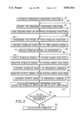
- the procedure used to effect the present invention begins with an estimate of the frequency response function 30.
- This first estimate can easily be produced by applying broadband noise with a flat power spectrum, i.e., white noise, such that the Aspec of X(f) equals a constant, to the system under analysis over the bandwidth of interest and then converting the output signal to the frequency domain, as described above.
- the estimated function is then inverted 32 and its square-root is taken 34.Inversion of frequency domain functions and taking their square roots are both facilities available in the 2642 Personal Fourier Analyzer.
- the phase of the square-root inverse estimated frequency response function is next randomized. Randomizing the phase 36 is optional, but preferred because it leads to a time domain stimulus signal that has its total energy more evenly distributed over a longer time, and is therefore more conserving of the available dynamic range of the channel22 used to monitor the stimulus signal. Phase randomization is another facility offered by 2642 Personal Fourier Analyzer.
- the randomized square-root inverse estimated frequency response function X(f) is then converted to the corresponding time domain stimulus signal x(t) by an inverse Fourier transform (IFT) 38.
- this stimulus signal is then scaled as appropriate 40. It is desirable to do this scaling, since using a stimulus signal with the maximum available amplitude conserves the dynamic range of the channel 24 being used to monitor the output.
- This scaled time domain version of the randomized square-root of the inverse of the estimated frequency transfer function isthen the stimulus signal, x(t), that is applied 42 to the system under analysis 12.
- the Fourier analyzer 20 monitors the stimulus signal x(t) 44 received on channel one 22. This monitored time domain stimulus signal is converted tothe frequency domain 46 to produce X(f) using an FFT process.
- the analyzer also monitors the system output signal y(t) 48 received on channel two 24 and performs an FFT operation on it to convert it to the frequency domain 50 producing Y(f).
- the randomized square-root inverse estimated frequency response function produced in step 40 could be used directly as X(f).
- the function processor 26 then calculates the cross power spectrum Cspec between these two functions, X(f) and Y(f).
- the function processor 26 also calculates the auto power spectrum, Aspec, on the stimulus function, X(f). Using these, the function processor 26 is then able to calculate 52 the frequency response function of the system under test according to equation (3) above.
- the calculation is complete 62.
- Whether or not the result is sufficiently accurate 54 can be determined bycalculating how closely the Cspec (cross power spectrum) of X(f) and Y(f) approximates a constant, since this Cspec function should approach a constant value as the calculated 52 value of the frequency response function approaches the true value.
- practical measurement limitations may prevent the cross power spectrum from actually achieving aperfectly flat profile. This could occur, for instance, if the combined dynamic range of both channels is insufficient to measure the system undertest, or if poor connection to the system under analysis is interfering with the measurement.
- step 54 exits "NO".
- the fastest, but least satisfactory, way to achieve improved accuracy is to repeat step 42 through 54 a number of times using the same scaled time domain version of the randomized square-root of the inverse ofthe estimated frequency response function according to loop 56. Averaging in this way over a number of calculations can be accomplished automatically by the 2642 Personal Fourier Analyzer.
- Improved results can be obtained by expanding the number of steps that are repeated according to loop 58. Using this procedure, the same square-root inverse estimated frequency response function is used repeatedly, but the phase randomization step 36, the converting to the time domain step 38, and the scaling step 40 are repeated again for each trial. This takes moretime but leads to improved results.
Landscapes
- Physics & Mathematics (AREA)
- Mathematical Physics (AREA)
- General Physics & Mathematics (AREA)
- Measurement Of Resistance Or Impedance (AREA)
Priority Applications (3)
| Application Number | Priority Date | Filing Date | Title |
|---|---|---|---|
| US07/464,486 US5051916A (en) | 1990-01-12 | 1990-01-12 | Stimulus signal generation method to maximize dynamic range in frequency response function calculations |
| DK004591A DK4591A (da) | 1990-01-12 | 1991-01-10 | Fremgangsmaade med frembringelse af stimuleringssignaler til maksimering af det dynamiske omraade ved beregning af frekvenssvarfunktioner |
| JP3013814A JPH0723901B2 (ja) | 1990-01-12 | 1991-01-11 | 周波数応答関数測定方法 |
Applications Claiming Priority (1)
| Application Number | Priority Date | Filing Date | Title |
|---|---|---|---|
| US07/464,486 US5051916A (en) | 1990-01-12 | 1990-01-12 | Stimulus signal generation method to maximize dynamic range in frequency response function calculations |
Publications (1)
| Publication Number | Publication Date |
|---|---|
| US5051916A true US5051916A (en) | 1991-09-24 |
Family
ID=23844131
Family Applications (1)
| Application Number | Title | Priority Date | Filing Date |
|---|---|---|---|
| US07/464,486 Expired - Lifetime US5051916A (en) | 1990-01-12 | 1990-01-12 | Stimulus signal generation method to maximize dynamic range in frequency response function calculations |
Country Status (3)
| Country | Link |
|---|---|
| US (1) | US5051916A (ja) |
| JP (1) | JPH0723901B2 (ja) |
| DK (1) | DK4591A (ja) |
Cited By (11)
| Publication number | Priority date | Publication date | Assignee | Title |
|---|---|---|---|---|
| US5291140A (en) * | 1990-07-13 | 1994-03-01 | Hewlett-Packard Company | Mixed domain spectrum measurement method |
| US6616254B1 (en) * | 1997-06-20 | 2003-09-09 | Itran Communications Ltd. | Code shift keying transmitter for use in a spread spectrum communications system |
| US20050240367A1 (en) * | 2004-04-21 | 2005-10-27 | Agilent Technologies, Inc. | Method of mapping linearly spaced spectrum points to logarithmically spaced frequency and a measuring apparatus using the method |
| US20070073797A1 (en) * | 2005-09-29 | 2007-03-29 | Lockheed Martin Corporation | Recursive method for solving the inexact greatest common divisor problem |
| US20080285615A1 (en) * | 2005-07-22 | 2008-11-20 | Dieter Fink | Method for Determining at Least One State Variable of an Electric Arc Furnace, and Electric Arc Furnace |
| US20090077150A1 (en) * | 2007-09-18 | 2009-03-19 | Amy Wendt | Method and system for controlling a voltage waveform |
| US20130054178A1 (en) * | 2011-08-30 | 2013-02-28 | Ou Eliko Tehnoloogia Arenduskeskus | Method and device for broadband analysis of systems and substances |
| US20130124489A1 (en) * | 2011-11-11 | 2013-05-16 | International Business Machines Corporation | Compressing a multivariate dataset |
| CN109598027A (zh) * | 2018-11-08 | 2019-04-09 | 合肥工业大学 | 一种基于频率响应函数修正结构模型参数的算法 |
| US11003809B2 (en) * | 2017-03-31 | 2021-05-11 | Cae Inc. | Repairing a model associated to a simulated interactive object |
| US11119151B2 (en) * | 2019-12-02 | 2021-09-14 | Rohde & Schwarz Gmbh & Co. Kg | Method for identifying and compensating for systems errors |
Citations (8)
| Publication number | Priority date | Publication date | Assignee | Title |
|---|---|---|---|---|
| US3710082A (en) * | 1970-03-03 | 1973-01-09 | Time Data Corp | System for digitally controlling a vibration testing environment or apparatus |
| US3848115A (en) * | 1973-10-19 | 1974-11-12 | Time Date Corp | Vibration control system |
| US4061017A (en) * | 1975-11-17 | 1977-12-06 | Time/Data Corporation | Structural analysis system |
| US4093988A (en) * | 1976-11-08 | 1978-06-06 | General Electric Company | High speed frequency response measurement |
| SU1049920A1 (ru) * | 1982-07-05 | 1983-10-23 | Предприятие П/Я Г-4173 | Устройство дл вычислени коэффициентов-фурье |
| US4703433A (en) * | 1984-01-09 | 1987-10-27 | Hewlett-Packard Company | Vector network analyzer with integral processor |
| US4713782A (en) * | 1984-08-23 | 1987-12-15 | Hewlett-Packard Company | Method and apparatus for measuring a transfer function |
| US4885708A (en) * | 1987-11-20 | 1989-12-05 | Advantest Corporation | Apparatus and method for measuring frequency response function |
-
1990
- 1990-01-12 US US07/464,486 patent/US5051916A/en not_active Expired - Lifetime
-
1991
- 1991-01-10 DK DK004591A patent/DK4591A/da not_active Application Discontinuation
- 1991-01-11 JP JP3013814A patent/JPH0723901B2/ja not_active Expired - Lifetime
Patent Citations (8)
| Publication number | Priority date | Publication date | Assignee | Title |
|---|---|---|---|---|
| US3710082A (en) * | 1970-03-03 | 1973-01-09 | Time Data Corp | System for digitally controlling a vibration testing environment or apparatus |
| US3848115A (en) * | 1973-10-19 | 1974-11-12 | Time Date Corp | Vibration control system |
| US4061017A (en) * | 1975-11-17 | 1977-12-06 | Time/Data Corporation | Structural analysis system |
| US4093988A (en) * | 1976-11-08 | 1978-06-06 | General Electric Company | High speed frequency response measurement |
| SU1049920A1 (ru) * | 1982-07-05 | 1983-10-23 | Предприятие П/Я Г-4173 | Устройство дл вычислени коэффициентов-фурье |
| US4703433A (en) * | 1984-01-09 | 1987-10-27 | Hewlett-Packard Company | Vector network analyzer with integral processor |
| US4713782A (en) * | 1984-08-23 | 1987-12-15 | Hewlett-Packard Company | Method and apparatus for measuring a transfer function |
| US4885708A (en) * | 1987-11-20 | 1989-12-05 | Advantest Corporation | Apparatus and method for measuring frequency response function |
Non-Patent Citations (4)
| Title |
|---|
| Digital Signal Analysis, by Roth et al., Br el & Kyaer, Jan. 1985. * |
| Digital Signal Analysis, by Roth et al., Bruel & Kyaer, Jan. 1985. |
| Introduction to Communication Systems, by Ferrel G. Stremler, New York, Addison Wesley Publishing Company, 1982. * |
| Introduction to Communication Systems, by Ferrel G. Stremler, New York, Addison-Wesley Publishing Company, 1982. |
Cited By (18)
| Publication number | Priority date | Publication date | Assignee | Title |
|---|---|---|---|---|
| US5291140A (en) * | 1990-07-13 | 1994-03-01 | Hewlett-Packard Company | Mixed domain spectrum measurement method |
| US6616254B1 (en) * | 1997-06-20 | 2003-09-09 | Itran Communications Ltd. | Code shift keying transmitter for use in a spread spectrum communications system |
| US20050240367A1 (en) * | 2004-04-21 | 2005-10-27 | Agilent Technologies, Inc. | Method of mapping linearly spaced spectrum points to logarithmically spaced frequency and a measuring apparatus using the method |
| US7317999B2 (en) * | 2004-04-21 | 2008-01-08 | Agilent Technologies, Inc. | Method of mapping linearly spaced spectrum points to logarithmically spaced frequency and a measuring apparatus using the method |
| US20080285615A1 (en) * | 2005-07-22 | 2008-11-20 | Dieter Fink | Method for Determining at Least One State Variable of an Electric Arc Furnace, and Electric Arc Furnace |
| US9255303B2 (en) | 2005-07-22 | 2016-02-09 | Siemens Aktiengesellschaft | Method for determining at least one state variable of an electric arc furnace, and electric arc furnace |
| US20100315098A1 (en) * | 2005-07-22 | 2010-12-16 | Dieter Fink | Method for determining at least one state variable of an electric arc furnace, and electric arc furnace |
| US20070073797A1 (en) * | 2005-09-29 | 2007-03-29 | Lockheed Martin Corporation | Recursive method for solving the inexact greatest common divisor problem |
| US8140292B2 (en) * | 2007-09-18 | 2012-03-20 | Wisconsin Alumni Research Foundation | Method and system for controlling a voltage waveform |
| US20090077150A1 (en) * | 2007-09-18 | 2009-03-19 | Amy Wendt | Method and system for controlling a voltage waveform |
| US20130054178A1 (en) * | 2011-08-30 | 2013-02-28 | Ou Eliko Tehnoloogia Arenduskeskus | Method and device for broadband analysis of systems and substances |
| EP2565654A2 (en) | 2011-08-30 | 2013-03-06 | Tallinn University of Technology | Method and device for broadband analysis of systems and substances |
| US10698023B2 (en) * | 2011-08-30 | 2020-06-30 | Tallinn University Of Technology | Method and device for broadband analysis of systems and substances |
| US20130124489A1 (en) * | 2011-11-11 | 2013-05-16 | International Business Machines Corporation | Compressing a multivariate dataset |
| US9009119B2 (en) * | 2011-11-11 | 2015-04-14 | International Business Machines Corporation | Compressing a multivariate dataset |
| US11003809B2 (en) * | 2017-03-31 | 2021-05-11 | Cae Inc. | Repairing a model associated to a simulated interactive object |
| CN109598027A (zh) * | 2018-11-08 | 2019-04-09 | 合肥工业大学 | 一种基于频率响应函数修正结构模型参数的算法 |
| US11119151B2 (en) * | 2019-12-02 | 2021-09-14 | Rohde & Schwarz Gmbh & Co. Kg | Method for identifying and compensating for systems errors |
Also Published As
| Publication number | Publication date |
|---|---|
| DK4591A (da) | 1991-07-13 |
| DK4591D0 (da) | 1991-01-10 |
| JPH0723901B2 (ja) | 1995-03-15 |
| JPH05149984A (ja) | 1993-06-15 |
Similar Documents
| Publication | Publication Date | Title |
|---|---|---|
| KR100708036B1 (ko) | 피시험 장치의 특성화 방법 | |
| Chen et al. | Extended real model of Kalman filter for time-varying harmonics estimation | |
| US5051916A (en) | Stimulus signal generation method to maximize dynamic range in frequency response function calculations | |
| US8854030B2 (en) | Method and device for frequency response measurement | |
| US10698023B2 (en) | Method and device for broadband analysis of systems and substances | |
| JP2006105984A (ja) | デジタル装置を測定する方法及び装置 | |
| JPH04229B2 (ja) | ||
| JP3234339B2 (ja) | 電力測定装置および方法 | |
| Petri | Frequency-domain testing of waveform digitizers | |
| KR20040014976A (ko) | 코히어런트하지 않게 샘플링된 데이타의 파워 스펙트럼을측정하기 위한 저누설 방법 | |
| Nuccio et al. | Assessment of virtual instruments measurement uncertainty | |
| US20180106842A1 (en) | Impedance Measurement through Waveform Monitoring | |
| US20090290658A1 (en) | Multi-Pulse Signal Generator Based on a Sawtooth Chirp | |
| US4813001A (en) | AC calibration method and device by determining transfer characteristics | |
| Belega et al. | Statistical performance of the effective-number-of-bit estimators provided by the sine-fitting algorithms | |
| KR100464119B1 (ko) | 최적화 기법을 적용한 전력진동 댐핑율 계산방법 | |
| Nunzi et al. | A procedure for highly reproducible measurements of ADC spectral parameters | |
| Chiorboli et al. | Analysis of distortion in A/D converters by time-domain and code-density techniques | |
| EP1345102B1 (en) | Simultaneous rapid open and closed loop bode plot measurement using a binary pseudo-random sequence | |
| JP4279356B2 (ja) | 掃引周波数装置試験 | |
| Silva et al. | Novel IEEE-STD-1241-Based Test Methods for Analog-to-Information Converter | |
| Liu et al. | An ENOB Evaluation Method for an Acquisition Channel | |
| CN117761393B (zh) | 一种时域信号的获取方法及装置 | |
| Garg et al. | Dynamic Parameter Estimation of Analog to Digital Converter with Multipoint Interpolation Technique | |
| Riederer | Transfer function measurements in audio |
Legal Events
| Date | Code | Title | Description |
|---|---|---|---|
| AS | Assignment |
Owner name: TEKTRONIX, INC. AN OR CORPORATION, OREGON Free format text: ASSIGNMENT OF ASSIGNORS INTEREST.;ASSIGNOR:BENSON, RICHARD A.;REEL/FRAME:005748/0865 Effective date: 19900109 |
|
| STCF | Information on status: patent grant |
Free format text: PATENTED CASE |
|
| FEPP | Fee payment procedure |
Free format text: PAYOR NUMBER ASSIGNED (ORIGINAL EVENT CODE: ASPN); ENTITY STATUS OF PATENT OWNER: LARGE ENTITY |
|
| FPAY | Fee payment |
Year of fee payment: 4 |
|
| AS | Assignment |
Owner name: MICRON TECHNOLOGY, INC., IDAHO Free format text: ASSIGNMENT OF ASSIGNORS INTEREST;ASSIGNOR:TEKTRONIX, INC.;REEL/FRAME:007715/0974 Effective date: 19951003 |
|
| FPAY | Fee payment |
Year of fee payment: 8 |
|
| FPAY | Fee payment |
Year of fee payment: 12 |