US5051175A - Drain guard - Google Patents
Drain guard Download PDFInfo
- Publication number
- US5051175A US5051175A US07/453,508 US45350889A US5051175A US 5051175 A US5051175 A US 5051175A US 45350889 A US45350889 A US 45350889A US 5051175 A US5051175 A US 5051175A
- Authority
- US
- United States
- Prior art keywords
- drain
- openings
- guard
- spaced
- drain opening
- Prior art date
- Legal status (The legal status is an assumption and is not a legal conclusion. Google has not performed a legal analysis and makes no representation as to the accuracy of the status listed.)
- Expired - Lifetime
Links
Images

Classifications
-
- E—FIXED CONSTRUCTIONS
- E04—BUILDING
- E04D—ROOF COVERINGS; SKY-LIGHTS; GUTTERS; ROOF-WORKING TOOLS
- E04D13/00—Special arrangements or devices in connection with roof coverings; Protection against birds; Roof drainage ; Sky-lights
- E04D13/04—Roof drainage; Drainage fittings in flat roofs, balconies or the like
- E04D13/0404—Drainage on the roof surface
- E04D13/0409—Drainage outlets, e.g. gullies
- E04D2013/0413—Strainers for drainage outlets
-
- E—FIXED CONSTRUCTIONS
- E04—BUILDING
- E04D—ROOF COVERINGS; SKY-LIGHTS; GUTTERS; ROOF-WORKING TOOLS
- E04D13/00—Special arrangements or devices in connection with roof coverings; Protection against birds; Roof drainage ; Sky-lights
- E04D13/04—Roof drainage; Drainage fittings in flat roofs, balconies or the like
- E04D13/0404—Drainage on the roof surface
- E04D13/0459—Drainage borders, e.g. dripping edges, gravel stops or dispersers
- E04D2013/0472—Gravel stops
Definitions
- the present invention relates to a drain guard and drain protection system and, more particularly, to a drain guard and drain protection system for roof drains.
- Flat roofs are typically equipped with one or more drains to remove precipitation and other water that collects on the roof surface. Rapid removal of such water is essential as its weight places great stress on a roof structure. If the weight of water on a roof reaches a sufficiently high amount, collapse of the roof structure can occur resulting in extensive property damage as well as grave injury to the building's occupants.
- Drain strainers have been used to prevent the clogging of roof drains by leaves, trash, and other solid materials which deposit on a roof surface. These solid materials are readily carried to a drain opening by the force of draining water.
- One commonly used type of drain strainer consists of a domed-shaped housing perforated with spaced multiple openings. Placed over the mouth of a drain opening of approximately the same perimeter, this type of drain strainer filters the draining water by permitting the water to flow through the multiple openings while blocking solid materials being carried by the force of the draining water.
- drain strainer Because the drain strainer's perimeter approximates that of the drain opening, its filtering capacity is limited. As a consequence, only a relatively small amount of solid materials need accumulate around the outer surface of the drain strainer for the multiple openings to become sealed, and water flow to the drain opening thereby blocked. Once water flow is blocked, water will collect on the roof surface and pose the hazards of structural damage, including roof collapse, and bodily injury. Additionally, this type of drain strainer is often constructed of polyvinyl chloride or other polymer. Exposure to sunlight, temperature changes, and other weather conditions causes the polymer strainer to become brittle and weakened. Consequently, the degraded polymer will eventually fracture.
- fracturing of the weakened polymer drain strainer can occur much more readily because the surrounding ballast, by the force of draining water, repeatedly impacts the drain guard. Once fractured, solid materials being carried by the force of draining water freely pass into and soon clog the drain opening.
- auxiliary drain protector was disclosed surrounding a primary protector of lesser periphery.
- both the primary and auxiliary drain protectors only had uniformly spaced sidewall openings and hence did not provide enhanced flow of draining water to a drain opening.
- a drain guard comprising a frame having a base and upstanding sidewall extending therefrom.
- the upstanding sidewall has a plurality of spaced openings with adjacent openings being vertically offset to optimize fluid flow.
- the base may have a plurality of openings in communication with the openings in the upstanding sidewall positioned relative thereto.
- the plurality of spaced upstanding sidewall openings may uniformly extend to the junction of the base and upstanding sidewall and communicate with the plurality of spaced base openings.
- a drain protection system which includes a ballasted surface layer such as a roof, a drain opening extending through the surface layer, and a portion on the surface layer cleared of ballast outwardly extending from a drain opening to a drain guard.
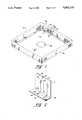
- FIG. 1 is a plan view of the drain guard of the present invention
- FIG. 2 is a sectional view taken substantially along the line 2--2 of FIG. 1;
- FIG. 3 is a plan view of the drain protection system of the present invention.
- the drain guard 10 includes a cross-sectionally L-shaped frame 12 having a base 14 and an upstanding sidewall 16 having a plurality of spaced openings 18 extending therethrough. Openings 18 are preferably oblong-shaped as such a configuration has been found to optimize fluid flow there through. Circular, rectangular and other openingshapes known to those in the art may also be utilized. Adjacent plurality of spaced openings 18 are vertically offset from one another as, for example, opening 20 is offset from opening 22. Alternating openings 18 arealso preferably uniformly positioned and sized. The foregoing arrangements are believed to provide better drainage particularly at increased water levels while maintaining the necessary strength and integrity of the frame12.
- the base 14 has a plurality of spaced openings 24 extending from the junction 26 of the base 14 and upstanding sidewall 16.
- the base openings 24 are in communication with the upstanding sidewall openings 18 positioned relative therewith.
- the perimeter of frame 12 is substantially greater than the perimeter of the drain opening 28.
- the perimeter of the frame is at least sixteen times greater than the perimeter of the drain opening.
- Enhancing the flow of draining water through the drain guard is critical, particularly at times when the volume of draining water is large, for example during a severe rainstorm. If the rate of water accumulation on a roof is greater than the flow rate through the drain guard, water will accumulate placing hazardous stress on the roof structure.
- each of the upstanding sidewall openings 18 may have a corresponding base opening 24 in communication therewith, it has also beenfound that by alternating the sidewall openings 18 so that every other sidewall opening 18 has an associated base opening 24 positioned thereto, the structural integrity of the drain guard is improved.
- the base plurality of openings 24 are advantageous as water will accumulateon the roof surface only to a depth equal to the thickness of the base 14 before the water drains through the drain guard 10 and to the drain opening 28. Hence, only a negligible volume of water will accumulate on a roof before passing through the drain guard 10 and stress to the roof structure is thereby avoided.
- the drain guard 10 is preferably constructed of 3.2 millimeter flat aluminum sheets, although other materials, such as other metals or a polymer, and other sheet dimensions should also provide an acceptable drain guard.
- the upstanding sidewall plurality of openings 18 and base plurality of openings 24 are mechanically stamped out of the flat aluminumsheets.
- the base 14 and upstanding sidewall 16 are then formed by folding the aluminum sheet along junction 26.
- the ends of the folded aluminum sheet are preferably mitered and then fastened by bolts, welding or other means known to those skilled in the art to the ends of like folded aluminum sheets to provide the frame 12.
- the drain protection system 40 includes a roof or other surface layer 42 having ballast 44 spread along the surface layer 42.
- the ballast 44 serves to secure the surface layer 42 to the underlyingsupport member.
- a drain opening 28 extends through the surface layer 42 to receive draining water.
- a portion 46 of the surface layer 42 has been cleared of ballast, the portion 46 outwardly extending from the drain opening to the drain guard 10.
- the drain guard 10 is of the type describedin reference to FIG. 1 and FIG. 2.
- ballast 44 from portion 46 provides increased fluid flow of draining water to drain opening 28 relative to a similar system where ballast 44 has not been removed from portion 46. Again, by enhancing the flow of water through the drain protection system,accumulation of water on the roof is minimized, and stress on the roof structure is thereby avoided. The removal of ballast 44 from portion 46 also prevents ballast clogging the drain opening 28. Moreover, the weight of the drain guard 10 serves the purpose of the ballast removed from portion 46 by securing the surface layer 42 to the underlying support member.
- a conventional drain strainer of approximately the same perimeter as the drain opening may be used in combination with the drain protection system 40.
- the drain protection system prevents ballast from collecting around the conventional drain strainer and thereby impeding water flow to the drain opening.
- removal of the ballast 44 prevents the fracturing of a weakened polymer drain strainer resulting from impacting ballast.
Landscapes
- Engineering & Computer Science (AREA)
- Architecture (AREA)
- Civil Engineering (AREA)
- Structural Engineering (AREA)
- Roof Covering Using Slabs Or Stiff Sheets (AREA)
Abstract
Description
Claims (4)
Priority Applications (1)
| Application Number | Priority Date | Filing Date | Title |
|---|---|---|---|
| US07/453,508 US5051175A (en) | 1989-12-20 | 1989-12-20 | Drain guard |
Applications Claiming Priority (1)
| Application Number | Priority Date | Filing Date | Title |
|---|---|---|---|
| US07/453,508 US5051175A (en) | 1989-12-20 | 1989-12-20 | Drain guard |
Publications (1)
| Publication Number | Publication Date |
|---|---|
| US5051175A true US5051175A (en) | 1991-09-24 |
Family
ID=23800830
Family Applications (1)
| Application Number | Title | Priority Date | Filing Date |
|---|---|---|---|
| US07/453,508 Expired - Lifetime US5051175A (en) | 1989-12-20 | 1989-12-20 | Drain guard |
Country Status (1)
| Country | Link |
|---|---|
| US (1) | US5051175A (en) |
Cited By (13)
| Publication number | Priority date | Publication date | Assignee | Title |
|---|---|---|---|---|
| US5154024A (en) * | 1991-09-19 | 1992-10-13 | Noel John A | Floor sink/drain installation method and apparatus |
| EP0626485A1 (en) * | 1993-05-24 | 1994-11-30 | Nill, Werner | Drainage device for rainwater |
| US5744048A (en) * | 1996-03-01 | 1998-04-28 | Storm Water Systems, Inc. | Clog resistant storm drain filter |
| US20080251470A1 (en) * | 2007-04-12 | 2008-10-16 | John Kent | Storm sewer drainage grate filter |
| US20090229195A1 (en) * | 2008-03-13 | 2009-09-17 | John Murphy | Grave marker grid support system |
| US7614198B1 (en) | 2004-04-29 | 2009-11-10 | Piskula James S | Method for providing existing building flat roof with drain restrictors |
| US20090277114A1 (en) * | 2007-01-09 | 2009-11-12 | The Tile Shop | Drain installation kit |
| CH702150A1 (en) * | 2009-11-10 | 2011-05-13 | Gabs Ag | Chip angle bracket for use in holder, has steel plate beveled along bending line, and recesses extended over bending line and including slots, which extend over surfaces of sheet metal sections run perpendicular to bending line |
| US7946087B1 (en) | 2008-05-19 | 2011-05-24 | Seitzinger James B | Roof drain sump box |
| US20120079777A1 (en) * | 2010-10-01 | 2012-04-05 | Dearmond Jr Thomas H | Apparatus and method for stabilizing headstones |
| EP3450648A1 (en) * | 2017-08-30 | 2019-03-06 | Msquared Groep B.V. | Retaining device |
| US20200217055A1 (en) * | 2017-07-21 | 2020-07-09 | Russell Wayne Robillard | Liquid waste receptor |
| CH720614A1 (en) * | 2023-03-17 | 2024-09-30 | Profilsager Ag | Retaining element for retaining a bulk material containing a profile element |
Citations (15)
| Publication number | Priority date | Publication date | Assignee | Title |
|---|---|---|---|---|
| DE211202C (en) * | ||||
| DE203508C (en) * | ||||
| US528888A (en) * | 1894-11-06 | Draining device | ||
| AT14642B (en) * | 1902-01-31 | 1904-01-11 | Karl Aug Roth Fa | Unsoldered gravel protection strip. |
| US1252548A (en) * | 1917-10-04 | 1918-01-08 | Gustave Carlson | Drain-connector. |
| US1593550A (en) * | 1923-03-13 | 1926-07-20 | Holt Roof Connection Company | Roof connection |
| US1761257A (en) * | 1929-04-09 | 1930-06-03 | Wells S Fleming | Roof-drain fixture |
| DE1006833B (en) * | 1953-03-21 | 1957-04-25 | Micafil Ag | Dismountable filter nozzle for quick filter systems, consisting of a socket fixed in the base plate, a head piece screwed into this, a filter ring arranged in between and a drain pipe |
| US2807368A (en) * | 1955-03-17 | 1957-09-24 | Margaret Czibere | Anti-clogging device for roof drains |
| US3121682A (en) * | 1960-08-01 | 1964-02-18 | Alice R Alberico | Drain protector |
| FI35134A (en) * | 1963-04-26 | 1965-07-10 | Katepal Oy | Flat roof manhole |
| US3517813A (en) * | 1968-09-16 | 1970-06-30 | Kunibert Thaler | Roof drain |
| US4035297A (en) * | 1975-11-13 | 1977-07-12 | Aldridge Malcolm G | Closure for roof drain |
| US4107929A (en) * | 1977-06-20 | 1978-08-22 | Kontekla Oy | Rain water roof outlet or similar for a building |
| US4418432A (en) * | 1981-08-26 | 1983-12-06 | Vidal Stella M | Drain filter having filamentary surface irregularities to entangle hair and debris |
-
1989
- 1989-12-20 US US07/453,508 patent/US5051175A/en not_active Expired - Lifetime
Patent Citations (15)
| Publication number | Priority date | Publication date | Assignee | Title |
|---|---|---|---|---|
| DE211202C (en) * | ||||
| DE203508C (en) * | ||||
| US528888A (en) * | 1894-11-06 | Draining device | ||
| AT14642B (en) * | 1902-01-31 | 1904-01-11 | Karl Aug Roth Fa | Unsoldered gravel protection strip. |
| US1252548A (en) * | 1917-10-04 | 1918-01-08 | Gustave Carlson | Drain-connector. |
| US1593550A (en) * | 1923-03-13 | 1926-07-20 | Holt Roof Connection Company | Roof connection |
| US1761257A (en) * | 1929-04-09 | 1930-06-03 | Wells S Fleming | Roof-drain fixture |
| DE1006833B (en) * | 1953-03-21 | 1957-04-25 | Micafil Ag | Dismountable filter nozzle for quick filter systems, consisting of a socket fixed in the base plate, a head piece screwed into this, a filter ring arranged in between and a drain pipe |
| US2807368A (en) * | 1955-03-17 | 1957-09-24 | Margaret Czibere | Anti-clogging device for roof drains |
| US3121682A (en) * | 1960-08-01 | 1964-02-18 | Alice R Alberico | Drain protector |
| FI35134A (en) * | 1963-04-26 | 1965-07-10 | Katepal Oy | Flat roof manhole |
| US3517813A (en) * | 1968-09-16 | 1970-06-30 | Kunibert Thaler | Roof drain |
| US4035297A (en) * | 1975-11-13 | 1977-07-12 | Aldridge Malcolm G | Closure for roof drain |
| US4107929A (en) * | 1977-06-20 | 1978-08-22 | Kontekla Oy | Rain water roof outlet or similar for a building |
| US4418432A (en) * | 1981-08-26 | 1983-12-06 | Vidal Stella M | Drain filter having filamentary surface irregularities to entangle hair and debris |
Cited By (17)
| Publication number | Priority date | Publication date | Assignee | Title |
|---|---|---|---|---|
| US5154024A (en) * | 1991-09-19 | 1992-10-13 | Noel John A | Floor sink/drain installation method and apparatus |
| EP0626485A1 (en) * | 1993-05-24 | 1994-11-30 | Nill, Werner | Drainage device for rainwater |
| US5744048A (en) * | 1996-03-01 | 1998-04-28 | Storm Water Systems, Inc. | Clog resistant storm drain filter |
| US7614198B1 (en) | 2004-04-29 | 2009-11-10 | Piskula James S | Method for providing existing building flat roof with drain restrictors |
| US20090277114A1 (en) * | 2007-01-09 | 2009-11-12 | The Tile Shop | Drain installation kit |
| US20080251470A1 (en) * | 2007-04-12 | 2008-10-16 | John Kent | Storm sewer drainage grate filter |
| US20090229195A1 (en) * | 2008-03-13 | 2009-09-17 | John Murphy | Grave marker grid support system |
| US7637061B2 (en) * | 2008-03-13 | 2009-12-29 | Plinths And Caissons, Llc | Grave marker grid support system |
| US7946087B1 (en) | 2008-05-19 | 2011-05-24 | Seitzinger James B | Roof drain sump box |
| CH702150A1 (en) * | 2009-11-10 | 2011-05-13 | Gabs Ag | Chip angle bracket for use in holder, has steel plate beveled along bending line, and recesses extended over bending line and including slots, which extend over surfaces of sheet metal sections run perpendicular to bending line |
| US20120079777A1 (en) * | 2010-10-01 | 2012-04-05 | Dearmond Jr Thomas H | Apparatus and method for stabilizing headstones |
| US8561363B2 (en) * | 2010-10-01 | 2013-10-22 | Thomas H. DeArmond, Jr. | Apparatus and method for stabilizing headstones |
| US20200217055A1 (en) * | 2017-07-21 | 2020-07-09 | Russell Wayne Robillard | Liquid waste receptor |
| US11808020B2 (en) * | 2017-07-21 | 2023-11-07 | Russell Wayne Robillard | Liquid waste receptor |
| EP3450648A1 (en) * | 2017-08-30 | 2019-03-06 | Msquared Groep B.V. | Retaining device |
| NL2019465B1 (en) * | 2017-08-30 | 2019-03-11 | Msquared Groep B V | Reversing device |
| CH720614A1 (en) * | 2023-03-17 | 2024-09-30 | Profilsager Ag | Retaining element for retaining a bulk material containing a profile element |
Similar Documents
| Publication | Publication Date | Title |
|---|---|---|
| US5051175A (en) | Drain guard | |
| US5640810A (en) | Gutter cover | |
| US6017166A (en) | Catch basin guard and filter | |
| US5813173A (en) | Gutter protector | |
| US5535554A (en) | Gutter and drain spout guard | |
| US4351134A (en) | Hinged gutter guard | |
| US5109640A (en) | Screen for a rain gutter | |
| US2583422A (en) | Building construction | |
| US5284580A (en) | Refuse collecting frame for sewer | |
| US5843306A (en) | Temporary silt guard for storm water collection basin inlet | |
| US5251410A (en) | Rain gutter cover | |
| US6261445B1 (en) | Temporary silt guard for sewer inlet | |
| US5257482A (en) | Roof gutter screen | |
| US5099620A (en) | Rain gutter cover | |
| US7200969B2 (en) | Down spout guard made from non-woven material | |
| US20050279036A1 (en) | Eavestrough guards | |
| US20070175106A1 (en) | Down spout guard made from non-woven material | |
| KR102301318B1 (en) | Drainage grating structure | |
| GB2372764A (en) | Gutter protector and guttering incorporating same | |
| US3121682A (en) | Drain protector | |
| US5170596A (en) | Double gutter assembly | |
| DE3536266A1 (en) | Rain-gutter covering for preventing soiling of the gutter | |
| KR102714971B1 (en) | Grating cover assembly for rainwater gutter | |
| CN218116990U (en) | Rainwater pipe anti-clogging device | |
| AU595041B2 (en) | Disposal of particulate waste |
Legal Events
| Date | Code | Title | Description |
|---|---|---|---|
| AS | Assignment |
Owner name: ROOF ACCESSORIES COMPANY, INC.,, MASSACHUSETTS Free format text: ASSIGNMENT OF ASSIGNORS INTEREST.;ASSIGNORS:WALCZAK, THOMAS W.;BENNETTE, ROBERT M.;REEL/FRAME:005200/0223 Effective date: 19891214 |
|
| STCF | Information on status: patent grant |
Free format text: PATENTED CASE |
|
| FEPP | Fee payment procedure |
Free format text: PAYOR NUMBER ASSIGNED (ORIGINAL EVENT CODE: ASPN); ENTITY STATUS OF PATENT OWNER: LARGE ENTITY |
|
| FPAY | Fee payment |
Year of fee payment: 4 |
|
| FPAY | Fee payment |
Year of fee payment: 8 |
|
| FEPP | Fee payment procedure |
Free format text: PAYER NUMBER DE-ASSIGNED (ORIGINAL EVENT CODE: RMPN); ENTITY STATUS OF PATENT OWNER: LARGE ENTITY Free format text: PAYOR NUMBER ASSIGNED (ORIGINAL EVENT CODE: ASPN); ENTITY STATUS OF PATENT OWNER: LARGE ENTITY Free format text: PAT HOLDER NO LONGER CLAIMS SMALL ENTITY STATUS, ENTITY STATUS SET TO UNDISCOUNTED (ORIGINAL EVENT CODE: STOL); ENTITY STATUS OF PATENT OWNER: LARGE ENTITY |
|
| REFU | Refund |
Free format text: REFUND - 11.5 YR SURCHARGE- LATE PMT W/IN 6 MO, SMALL ENTITY (ORIGINAL EVENT CODE: R2556); ENTITY STATUS OF PATENT OWNER: LARGE ENTITY Free format text: REFUND - PAYMENT OF MAINTENANCE FEE, 12TH YR, SMALL ENTITY (ORIGINAL EVENT CODE: R2553); ENTITY STATUS OF PATENT OWNER: LARGE ENTITY |
|
| AS | Assignment |
Owner name: OLYMPIC MANUFACTURING GROUP, INC., MASSACHUSETTS Free format text: ASSIGNMENT OF ASSIGNORS INTEREST;ASSIGNOR:ROOF ACCESSORIES COMPANY, INC.;REEL/FRAME:013758/0074 Effective date: 20030203 |
|
| REMI | Maintenance fee reminder mailed | ||
| FPAY | Fee payment |
Year of fee payment: 12 |
|
| SULP | Surcharge for late payment |
Year of fee payment: 11 |
|
| AS | Assignment |
Owner name: CONGRESS FINANCIAL CORPORATION, AS AGENT, NEW YORK Free format text: SECURITY INTEREST;ASSIGNOR:OLYMPIC MANUFACTURING GROUP, INC.;REEL/FRAME:015361/0274 Effective date: 20040331 |
|
| AS | Assignment |
Owner name: ABLECO FINANCE LLC, NEW YORK Free format text: SECURITY INTEREST;ASSIGNOR:OLYMPIC MANUFACTURING GROUP, INC.;REEL/FRAME:015246/0001 Effective date: 20040330 |
|
| AS | Assignment |
Owner name: CANPARTNERS INVESTMENTS IV, LLC, AS COLLATERAL AGE Free format text: ASSIGNMENT OF SECURITY INTEREST;ASSIGNOR:ABLECO FINANCE LLC;REEL/FRAME:015334/0172 Effective date: 20041029 |
|
| AS | Assignment |
Owner name: STEEL PARTNERS II LIQUIDATING SERIES TRUST - SERIE Free format text: SECURITY AGREEMENT;ASSIGNOR:STEEL PARTNERS II, L.P.;REEL/FRAME:023741/0717 Effective date: 20090715 |
|
| AS | Assignment |
Owner name: ABLECO, L.L.C., AS AGENT, NEW YORK Free format text: PATENT COLLATERAL ASSIGNMENT AND SECURITY AGREEMENT;ASSIGNOR:OMG, INC. (F/K/A OLYMPIC MANUFACTURING GROUP, INC.);REEL/FRAME:025150/0295 Effective date: 20101015 Owner name: ABLECO, L.L.C., AS AGENT, NEW YORK Free format text: PATENT COLLATERAL ASSIGNMENT AND SECURITY AGREEMENT;ASSIGNOR:OMG, INC. (F/K/A OLYMPIC MANUFACTURING GROUP, INC.);REEL/FRAME:025150/0481 Effective date: 20101015 |
|
| AS | Assignment |
Owner name: OMG, INC., MASSACHUSETTS Free format text: RELEASE OF PATENT COLLATERAL ASSIGNMENTS;ASSIGNOR:ABELCO, L.L.C.;REEL/FRAME:029299/0620 Effective date: 20121108 |
|
| AS | Assignment |
Owner name: OMG, INC. (F/K/A OLYMPIC MANUFACTURING GROUP, INC. Free format text: RELEASE OF SECURITY INTEREST IN PATENTS;ASSIGNOR:WELLS FARGO BANK, NATIONAL ASSOCIATION;REEL/FRAME:029302/0414 Effective date: 20121108 |