US5050659A - Machine for the removal and replacement of tires for the wheels of automobiles - Google Patents
Machine for the removal and replacement of tires for the wheels of automobiles Download PDFInfo
- Publication number
- US5050659A US5050659A US07/515,967 US51596790A US5050659A US 5050659 A US5050659 A US 5050659A US 51596790 A US51596790 A US 51596790A US 5050659 A US5050659 A US 5050659A
- Authority
- US
- United States
- Prior art keywords
- machine
- platform
- stem
- cylinder
- arm
- Prior art date
- Legal status (The legal status is an assumption and is not a legal conclusion. Google has not performed a legal analysis and makes no representation as to the accuracy of the status listed.)
- Expired - Fee Related
Links
Images



Classifications
-
- B—PERFORMING OPERATIONS; TRANSPORTING
- B60—VEHICLES IN GENERAL
- B60B—VEHICLE WHEELS; CASTORS; AXLES FOR WHEELS OR CASTORS; INCREASING WHEEL ADHESION
- B60B30/00—Means for holding wheels or parts thereof
- B60B30/06—Means for holding wheels or parts thereof engaging the wheel body, e.g. the rim
-
- B—PERFORMING OPERATIONS; TRANSPORTING
- B60—VEHICLES IN GENERAL
- B60C—VEHICLE TYRES; TYRE INFLATION; TYRE CHANGING; CONNECTING VALVES TO INFLATABLE ELASTIC BODIES IN GENERAL; DEVICES OR ARRANGEMENTS RELATED TO TYRES
- B60C25/00—Apparatus or tools adapted for mounting, removing or inspecting tyres
- B60C25/01—Apparatus or tools adapted for mounting, removing or inspecting tyres for removing tyres from or mounting tyres on wheels
- B60C25/05—Machines
- B60C25/053—Support of wheel parts during machine operation
- B60C25/0545—Support of wheel parts during machine operation with rotary motion of tool or tyre support, e.g. turntables
-
- B—PERFORMING OPERATIONS; TRANSPORTING
- B60—VEHICLES IN GENERAL
- B60C—VEHICLE TYRES; TYRE INFLATION; TYRE CHANGING; CONNECTING VALVES TO INFLATABLE ELASTIC BODIES IN GENERAL; DEVICES OR ARRANGEMENTS RELATED TO TYRES
- B60C25/00—Apparatus or tools adapted for mounting, removing or inspecting tyres
- B60C25/01—Apparatus or tools adapted for mounting, removing or inspecting tyres for removing tyres from or mounting tyres on wheels
- B60C25/05—Machines
- B60C25/132—Machines for removing and mounting tyres
-
- B—PERFORMING OPERATIONS; TRANSPORTING
- B60—VEHICLES IN GENERAL
- B60B—VEHICLE WHEELS; CASTORS; AXLES FOR WHEELS OR CASTORS; INCREASING WHEEL ADHESION
- B60B2900/00—Purpose of invention
- B60B2900/50—Improvement of
- B60B2900/531—User-friendliness
-
- B—PERFORMING OPERATIONS; TRANSPORTING
- B60—VEHICLES IN GENERAL
- B60Y—INDEXING SCHEME RELATING TO ASPECTS CROSS-CUTTING VEHICLE TECHNOLOGY
- B60Y2200/00—Type of vehicle
- B60Y2200/10—Road Vehicles
- B60Y2200/11—Passenger cars; Automobiles
Definitions
- the present invention relates to a machine for the removal and replacement of tires for the wheels of automobiles.
- Said invention comprises a frame on which a self-centering platform is arranged, rotatable around a usually vertical axis on which the wheel rim can be centered and blocked.
- a post By the side of the platform and fixedly mounted to the frame of the machine is a post, at whose top a substantially horizontal arm is attached which at its free end is coupled in an axially slidable way with a vertical toolhead arm.
- an unbeading device is mounted, whose function is to detach the bead of the tire from the wheel before proceeding to the removal operation.
- Machines of this type in the present art are normally equipped with motorized means needing electrical power for at least part of the operation.
- Principal aim of the present invention is to provide a machine for the removal and replacement of tires which requires for its functioning only the power supplied by compressed air.
- a frame on which is arranged a self-centering platform rotatable around a vertical or almost vertical axis, on which the wheel rim is blocked and centered;
- a toolhead arm positionable above said platform coupled in an axially slidable way to the free end of said horizontal arm;
- an unbeading device mounted to one of the external sides of the machine.
- the machine further comprises:
- the second of two pneumatic motors comprising a pneumatic cylinder located co-axially to said platform and commanding, by the movement of its stem, the movement of the jaws for the gripping of the wheel blocked on said platform;
- a tank for the compressed air used in powering the machine comprising a straight tubular section structural element, whose convex external surface also forms part of the upper surface of the body of the machine itself, above which are arranged said platform and said post.
- Advantages of the present invention are its compactness and its operative simplicity.
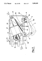
- FIG. 1 is a schematic side view in vertical elevation
- FIG. 2 is, in enlarged scale, a partial section made according to plane I--I of FIG. 1;
- FIG. 3 is a schematic partial section made according to plane II--II of FIG. 2;
- FIG. 4 is, in enlarged scale, part of a section made according to plane III--III;
- FIG. 5 is the simplified scheme of the pneumatic circuit for the supply of the various actuators with which the machine is equipped.
- FIG. 1 the box-shaped frame of the machine is represented, on the top of which are arranged the self-centering platform (2), rotatable around a vertical axis, on which the wheel is blocked and centered; and a fixed post (3) to whose top end is mounted at right angles a horizontal arm (4), which on its free end has a toolhead arm (5) attached.
- an unbeading devise (6) which essentially comprises a moving arm (7) pivoted at the side of the frame (1) by means of a vertical-axis pivot (8) and equipped at its free end with a trowel-shaped unbeading tool (9).
- the means for the blocking and positioning of the toolhead arm (5) and the horizontal arm (4) are of known type.
- the rotation of the self-centering arm (2) like the activating of the unbeading devise (6) are produced pneumatically by the action of one pneumatic cylinder (10) housed inside the frame (1).
- Said cylinder is equipped with two stems, the front section of one of them having a rack (13) externally positioned on it, which can engage with a pinion (14) coaxially mounted and idle on the shaft (15) of the rotatable platform (2).
- the pinion (14) exhibits frontally a plurality of triangular teeth (16) corresponding to the teeth of a hub (17) coupled coaxially and axially slidably on same shaft (15).
- the hub (17) has a throat in which the ends of a fork (18) are inserted, whose parallel movements with respect to the axis of the shaft (15) determine the engagement or non-engagement of the frontal teeth (16) of the pinion (14) with those of the hub (17).
- a spring (19) acting on the hub (17), tends to hold the hub (17) and the pinion (14) in the engaged position, keeping them together during rotation.
- a small hydraulic cylinder (20) acts on the fork (18) to produce, antagonistically with regard to the spring (19), the distancing of the hub (17) from the pinion (14) and therefore the disengagement.
- the small cylinder (20) is constantly fed and begins emptying only when the work stroke of cylinder (20), aimed at producing rotation of the platform (2) is commanded via the activating of the valve (21).
- the self-centering platform (2) is free to rotate in either direction around its axis as long as the command which produces the engaging of the hub (17) with the pinion (14) is not given.
- the fact that the platform (2) is "normally" rotatably free is advantageous for the performance of those maneuvers, such as the positioning of the valve, insertion of the inner tube (if necessary) and the tire bead which the operator performs during the mounting of the tire.
- valve (22) On the compressed-air conduit which links the valve (21) to the small cylinder (20) a valve (22) is positioned in series, which is mechanically activated by action of the moving arm (7) of the unbeading devise (6).
- a fast-emptying valve (42) In the conduit which links said valve (21) with the cylinder (10) a fast-emptying valve (42) is positioned, by means of which, during the return stroke of the piston of the cylinder (10), the air is evacuated without passing through valve (21).
- the speed of the work stroke of the cylinder (10) is regulated by means of a hydraulic system associated with the front section of the stem (11) which exhibits externally the rack (13).
- Said front section of the stem (11) is internally hollow and therein is coupled with an axially slidable piston element (23), which is fixed to the frame (1).
- Said piston element (23) defines a closed chamber of variable volume (24) within the front part of the stem (11), which communicates with a reservoir (28) containing liquid under pressure through a conduit whose first part comprises a through-hole (25) bored in the piston element (23).
- a calibrated no-return valve (26) aimed at permitting the unidirectional flow of liquid from the reservoir (28) to the closed chamber (24), and an adjustable throttle valve (27) are located in parallel.
- the reservoir (28) is only partially filled with liquid and is pressurised by means of compressed air coming from a tank (59).
- the liquid contained in the closed chamber (24) is forced to flow to the reservoir (28) through the throttle valve (27) which by regulating the flow determines the velocity of the stem of the pneumatic cylinder (10).
- the flow inverts and almost all of the liquid flows from the reservoir (28) to the closed chamber (24) by going through the valve (26). In this way the return-stroke of the piston is effected.
- the coupling between the first section of the stem (11) and the piston element (23) is schematically represented by the hydraulic cylinder (29).
- the second section of the stem (12) of the piston of the cylinder (10) is attached to the end of a chain (30) which has its other end fixed to a point approximately halfway along the moving arm (7) of the unbeading devise (6).
- the chain (30) is bent around two idler wheels (31) and (32) and is linked to a spring (33) whose function is to maintain said chain (30) in a state of tension also when the second section of the stem (12) is fully out of the pneumatic cylinder (10) (rest position).
- the moving arm (7) which is pivoted by a vertical pivot (8) to the side of the frame (1), is held with its unbeading tool against a fixed striker (36) with the help of another spring (60).
- the moving arm (7) acts, via element (37), on the valve (22) keeping it in the position illustrated in FIG. 2.
- the valve (22) is put into the closed position and the small pneumatic cylinder (20) remains under pressure and maintains the hub (17) in a disengaged position with respect to the pinion (14).
- the valve (21) can be activated in order to command the activation of the pneumatic cylinder (10), which in its work-stroke pulls the moving arm, previously distanced by hand, to the striker (36) so that it can perform the unbeading operation.
- the platform (2) is not made to rotate by this action since the pinion (14) is disengaged from the rotatable hub (17) and idles on the shaft (15).
- the platform (2) is self-centering and is provided with a plurality of jaws (38) permitting the gripping of the wheel rim.
- the opening and closing movements of the rim-gripping jaws are effected by action of a second hydraulic cylinder (39) positioned coaxially to the shaft (15) of the platform (2) and commanded by means of a valve (40).
- the cylinder is fed by means of a coaxial conduit (41) bored in the lower part of the stem (39).
- each of which exhibits a slot (45) normal to the axis.
- the number of arms (44) is exactly equal to the number of jaws (38) present on the platform (2).
- Each jaw (38) functions mechanically as the member with a connecting rod function in a hinged parallelogram where the opposite member acts as frame.
- each jaw (38) The hinge pivot axes (46) and (47) of each jaw (38) are parallel.
- One of the members with crank function of each jaw (38) is formed by two parallel cornered levers (48), symmetrically coupled and provided with a coupling pivot (49) with axis parallel to the hinge axes (46) and (47), which fits into the slot (45) of the arm (44).
- the two cornered levers (48) are hinged to the body of the platform (2) by means of a pivot (50).
- the remaining member with crank function in said hinged parallelogram is represented by the rod (51) which is hinged, by one of its ends, to the jaw (38) by means of the hinge pivot (47) and by its other end to the body of the platform (2) by means of the pivot (52).
- each jaw (38) To the body of each jaw (38) is mounted a last section, or exit mouth (54) of a conduit (53) having a flexible intermediate section.
- the exit mouths (54) are located in proximity to the gripping organs of the jaws (38) with the aim of permitting, on command, the entrance of compressed air between the tire and the rim in order to begin the inflation of tires without inner tubes (this is to force the bead of the tire into position on the wheelhub).
- the compressed air is sent to the conduits (53) via an annular chamber (55) positioned coaxially external to the cylinder (39).
- the sending of the air to the conduits (53) is commanded by means of a pedal-action valve (56).
- FIG. 5 shows, coming from the tank (59), an air source whose function is the "normal" inflation of the tires.
- the use of this air source is made possible by the presence of a valve (61).
- the tank (59), linkable to the distribution network of compressed air, is constituted by a straight tubular-section structural element, part of whose convex exterior surface acts as part of the upper external body of the machine, on which are mounted the post (3) and the self-centering platform (2). To this structural element are mounted the side walls (57) and the upper wall (58), which together constitute the frame (2) of the machine.
Landscapes
- Engineering & Computer Science (AREA)
- Mechanical Engineering (AREA)
- Manipulator (AREA)
Abstract
Description
Claims (7)
Priority Applications (1)
| Application Number | Priority Date | Filing Date | Title |
|---|---|---|---|
| US07/515,967 US5050659A (en) | 1990-04-27 | 1990-04-27 | Machine for the removal and replacement of tires for the wheels of automobiles |
Applications Claiming Priority (1)
| Application Number | Priority Date | Filing Date | Title |
|---|---|---|---|
| US07/515,967 US5050659A (en) | 1990-04-27 | 1990-04-27 | Machine for the removal and replacement of tires for the wheels of automobiles |
Publications (1)
| Publication Number | Publication Date |
|---|---|
| US5050659A true US5050659A (en) | 1991-09-24 |
Family
ID=24053554
Family Applications (1)
| Application Number | Title | Priority Date | Filing Date |
|---|---|---|---|
| US07/515,967 Expired - Fee Related US5050659A (en) | 1990-04-27 | 1990-04-27 | Machine for the removal and replacement of tires for the wheels of automobiles |
Country Status (1)
| Country | Link |
|---|---|
| US (1) | US5050659A (en) |
Cited By (12)
| Publication number | Priority date | Publication date | Assignee | Title |
|---|---|---|---|---|
| EP0557618A1 (en) * | 1992-02-28 | 1993-09-01 | CORGHI S.p.A. | Bead release device for tyre removal machines |
| US5490552A (en) * | 1993-09-09 | 1996-02-13 | Vignoli; Giuliano | Pneumatically operated tire removal machine |
| US6062289A (en) * | 1998-03-24 | 2000-05-16 | Hennessy Industries, Inc. | Laminated clamp for rim holding tire changers |
| EP1245414A3 (en) * | 2001-03-27 | 2002-12-04 | GIULIANO S.r.l. | Device for rotary movement of vehicle wheel mounting flanges in tire changing machines |
| US20030131947A1 (en) * | 2002-01-17 | 2003-07-17 | Sicam S.R.L. | Assembly for actuation of lateral bead-breaking arm for tyre changing machines |
| US20110120660A1 (en) * | 2009-11-24 | 2011-05-26 | Aymar Brandon P | Car tire attachment mechanism |
| US8307874B1 (en) | 2008-01-25 | 2012-11-13 | Hunter Engineering Company | Tire changing method and machine with angularly positionable drive axis |
| US20150047789A1 (en) * | 2013-07-23 | 2015-02-19 | Hennessy Industries, Inc. | Tire Changing Machine With Bead Loosener Arm |
| WO2015170273A1 (en) * | 2014-05-07 | 2015-11-12 | Gino Ferrari | A de-beading device for tires changing machines |
| US20150343863A1 (en) * | 2014-05-30 | 2015-12-03 | Snap-On Equipment Srl A Unico Socio | Mounting/demounting tool unit with preloaded tool |
| ITUB20155378A1 (en) * | 2015-11-10 | 2017-05-10 | Snap On Equip Srl Unico Socio | Tire changer machine |
| WO2017081553A1 (en) * | 2015-11-10 | 2017-05-18 | Snap-On Equipment S.R.L. | Tyre changing machine |
Citations (4)
| Publication number | Priority date | Publication date | Assignee | Title |
|---|---|---|---|---|
| US3905413A (en) * | 1973-08-30 | 1975-09-16 | Clifford C Myers | Tubeless tire changer |
| US4209053A (en) * | 1977-08-10 | 1980-06-24 | Francis Du Quesne | Apparatus for fitting and removing an automobile tire |
| US4750538A (en) * | 1984-06-29 | 1988-06-14 | Francis Du Quesne | Mechanism for holding a wheel in a device for fitting tires to and removing tires from wheel rims |
| US4884611A (en) * | 1988-10-24 | 1989-12-05 | Schmidt Raymond H | Tire changing machine |
-
1990
- 1990-04-27 US US07/515,967 patent/US5050659A/en not_active Expired - Fee Related
Patent Citations (4)
| Publication number | Priority date | Publication date | Assignee | Title |
|---|---|---|---|---|
| US3905413A (en) * | 1973-08-30 | 1975-09-16 | Clifford C Myers | Tubeless tire changer |
| US4209053A (en) * | 1977-08-10 | 1980-06-24 | Francis Du Quesne | Apparatus for fitting and removing an automobile tire |
| US4750538A (en) * | 1984-06-29 | 1988-06-14 | Francis Du Quesne | Mechanism for holding a wheel in a device for fitting tires to and removing tires from wheel rims |
| US4884611A (en) * | 1988-10-24 | 1989-12-05 | Schmidt Raymond H | Tire changing machine |
Cited By (22)
| Publication number | Priority date | Publication date | Assignee | Title |
|---|---|---|---|---|
| US5381843A (en) * | 1992-02-22 | 1995-01-17 | Corghi - S.P.A. | Bead release device for tire removal machines |
| EP0557618A1 (en) * | 1992-02-28 | 1993-09-01 | CORGHI S.p.A. | Bead release device for tyre removal machines |
| US5490552A (en) * | 1993-09-09 | 1996-02-13 | Vignoli; Giuliano | Pneumatically operated tire removal machine |
| US6062289A (en) * | 1998-03-24 | 2000-05-16 | Hennessy Industries, Inc. | Laminated clamp for rim holding tire changers |
| EP1245414A3 (en) * | 2001-03-27 | 2002-12-04 | GIULIANO S.r.l. | Device for rotary movement of vehicle wheel mounting flanges in tire changing machines |
| US20030131947A1 (en) * | 2002-01-17 | 2003-07-17 | Sicam S.R.L. | Assembly for actuation of lateral bead-breaking arm for tyre changing machines |
| US8307874B1 (en) | 2008-01-25 | 2012-11-13 | Hunter Engineering Company | Tire changing method and machine with angularly positionable drive axis |
| US20110120660A1 (en) * | 2009-11-24 | 2011-05-26 | Aymar Brandon P | Car tire attachment mechanism |
| US8136567B2 (en) * | 2009-11-24 | 2012-03-20 | Aymar Brandon P | Car tire attachment mechanism |
| US9162544B2 (en) * | 2013-07-23 | 2015-10-20 | Hennessy Industries, Inc. | Tire changing machine with bead loosener arm |
| US20150047789A1 (en) * | 2013-07-23 | 2015-02-19 | Hennessy Industries, Inc. | Tire Changing Machine With Bead Loosener Arm |
| WO2015170273A1 (en) * | 2014-05-07 | 2015-11-12 | Gino Ferrari | A de-beading device for tires changing machines |
| US9873298B2 (en) | 2014-05-07 | 2018-01-23 | Gino Ferrari | De-beading device for tire-changing machines |
| US20150343863A1 (en) * | 2014-05-30 | 2015-12-03 | Snap-On Equipment Srl A Unico Socio | Mounting/demounting tool unit with preloaded tool |
| US11001108B2 (en) * | 2014-05-30 | 2021-05-11 | Snap-On Equipment Srl A Unico Socio | Mounting/demounting tool unit with preloaded tool |
| ITUB20155378A1 (en) * | 2015-11-10 | 2017-05-10 | Snap On Equip Srl Unico Socio | Tire changer machine |
| WO2017081553A1 (en) * | 2015-11-10 | 2017-05-18 | Snap-On Equipment S.R.L. | Tyre changing machine |
| CN108473010A (en) * | 2015-11-10 | 2018-08-31 | 斯耐普昂仪器有限公司 | tire changer |
| US20180370302A1 (en) * | 2015-11-10 | 2018-12-27 | Snap-On Equipment S.R.L. | Tyre changing machine |
| CN108473010B (en) * | 2015-11-10 | 2020-09-04 | 斯耐普昂仪器有限公司 | Tyre mounting/dismounting machine |
| US10828949B2 (en) * | 2015-11-10 | 2020-11-10 | Snap-On Equipment S.R.L. | Tyre changing machine |
| US11148482B2 (en) | 2015-11-10 | 2021-10-19 | Snap-On Equipment S.R.L. | Tyre changing machine |
Similar Documents
| Publication | Publication Date | Title |
|---|---|---|
| AU723510B1 (en) | Rivet setting device | |
| GB2050901A (en) | Torque control apparatus for pneumatic impact wrench | |
| US3225529A (en) | Tree shaking mechanism | |
| GB2040775A (en) | Blind riveting tool | |
| EP0039976A2 (en) | A device for the transfer of articles to be machined on machine tools from one work station to the next one | |
| JP2002262626A (en) | Rice transplanter | |
| US1146193A (en) | Fluid-pressure chuck-actuating machine. | |
| US3822797A (en) | Control valve operating mechanism | |
| US510036A (en) | Pump attachment for velocipedes | |
| US2587969A (en) | Motor-driven cutting and breaking machine | |
| WO2017022654A1 (en) | Vibration test machine | |
| US1869698A (en) | Steering mechanism for automobiles | |
| JP6952496B2 (en) | Industrial robot | |
| US3603206A (en) | Air-hydraulic linear feed device | |
| US2197848A (en) | Power lift attachment for tractors | |
| US572051A (en) | duryea | |
| CA2462016C (en) | Pneumatic strapping machine | |
| US707246A (en) | Pneumatic power-hammer. | |
| US1430292A (en) | Work clamping and cushioning attachment for pneumatic hammers | |
| IT201900015704A1 (en) | ELECTRONIC ACTUATOR FOR THE CONTROL OF A SEQUENTIAL GEARBOX | |
| JPH0387630A (en) | material testing machine | |
| JPH08323566A (en) | Drive shaft assembly equipment | |
| SU1454689A1 (en) | Adaptive clamping device | |
| SU1393523A1 (en) | Forge manipulator bar | |
| JP2002262623A (en) | Rice transplanter |
Legal Events
| Date | Code | Title | Description |
|---|---|---|---|
| AS | Assignment |
Owner name: G.S. S.R.L., ITALY Free format text: ASSIGNMENT OF ASSIGNORS INTEREST.;ASSIGNOR:SCALAMBRA, GIORGIO;REEL/FRAME:005323/0994 Effective date: 19900409 |
|
| FPAY | Fee payment |
Year of fee payment: 4 |
|
| REFU | Refund |
Free format text: REFUND - PAYMENT OF MAINTENANCE FEE, 8TH YR, SMALL ENTITY (ORIGINAL EVENT CODE: R284); ENTITY STATUS OF PATENT OWNER: LARGE ENTITY |
|
| LAPS | Lapse for failure to pay maintenance fees | ||
| FP | Lapsed due to failure to pay maintenance fee |
Effective date: 19990924 |
|
| AS | Assignment |
Owner name: G.S.S.R.L., ITALY Free format text: CHANGE OF NAME;ASSIGNOR:ORIZIA S.R.L.;REEL/FRAME:011122/0224 Effective date: 19991216 Owner name: ORIZIA S.R.L., ITALY Free format text: MERGER;ASSIGNOR:G.S. S.R.L.;REEL/FRAME:011219/0425 Effective date: 19991216 |
|
| AS | Assignment |
Owner name: SNAP-ON EQUIPMENT S.R.L., ITALY Free format text: CHANGE OF NAME;ASSIGNOR:G.S. S.R.L.;REEL/FRAME:013943/0792 Effective date: 20020930 |
|
| STCH | Information on status: patent discontinuation |
Free format text: PATENT EXPIRED DUE TO NONPAYMENT OF MAINTENANCE FEES UNDER 37 CFR 1.362 |