US5044408A - Device for moving the back rest in weaving machines - Google Patents
Device for moving the back rest in weaving machines Download PDFInfo
- Publication number
- US5044408A US5044408A US07/552,560 US55256090A US5044408A US 5044408 A US5044408 A US 5044408A US 55256090 A US55256090 A US 55256090A US 5044408 A US5044408 A US 5044408A
- Authority
- US
- United States
- Prior art keywords
- bolt
- driving wheel
- seating
- eccentric member
- back rest
- Prior art date
- Legal status (The legal status is an assumption and is not a legal conclusion. Google has not performed a legal analysis and makes no representation as to the accuracy of the status listed.)
- Expired - Fee Related
Links
- 238000009941 weaving Methods 0.000 title claims abstract description 18
- 230000007246 mechanism Effects 0.000 claims abstract description 17
- 230000008878 coupling Effects 0.000 claims description 24
- 238000010168 coupling process Methods 0.000 claims description 24
- 238000005859 coupling reaction Methods 0.000 claims description 24
- 210000000078 claw Anatomy 0.000 claims description 11
- 230000033001 locomotion Effects 0.000 description 22
- 230000010363 phase shift Effects 0.000 description 4
- 239000004744 fabric Substances 0.000 description 3
- 230000005540 biological transmission Effects 0.000 description 2
- 230000004048 modification Effects 0.000 description 2
- 238000012986 modification Methods 0.000 description 2
- 241001282160 Percopsis transmontana Species 0.000 description 1
- 235000014676 Phragmites communis Nutrition 0.000 description 1
- 230000008901 benefit Effects 0.000 description 1
- 230000008859 change Effects 0.000 description 1
- 238000010276 construction Methods 0.000 description 1
- 238000000034 method Methods 0.000 description 1
- 230000001360 synchronised effect Effects 0.000 description 1
Images


Classifications
-
- D—TEXTILES; PAPER
- D03—WEAVING
- D03D—WOVEN FABRICS; METHODS OF WEAVING; LOOMS
- D03D49/00—Details or constructional features not specially adapted for looms of a particular type
- D03D49/04—Control of the tension in warp or cloth
- D03D49/12—Controlling warp tension by means other than let-off mechanisms
- D03D49/14—Compensating for tension differences during shedding
Definitions
- the present invention concerns a device for moving the back rest in weaving machines, in particular according to a periodical movement.
- said periodical movement of the back rest can be obtained by means of an eccentric, driven by the main shaft of the weaving machine.
- This known embodiment is usually also provided with adjusting means to set the eccentricity.
- the setting of the eccentricity may involve a phase shift between the movements made respectively by the harnesses and the back rest. It is obvious that the phase between said movements has to be reset.
- the movement of the back rest has to be more or less in phase with the opening and closing of the shed. It is known, however, that, depending on the cloth to be woven, the movement of the harnesses in relation to the movement of the sley or the main shaft of the weaving machine may be changed. In order to obtain, in case of such a change, that said movement of the back rest, which has been obtained by the movement of the main shaft, remains in phase with the opening and closing of the shed, also the phase between the main shaft and the movement of the back rest has to be set.
- this is done by driving the eccentric by means of a gear wheel clutch, such that, through the release of these clutches and through the mutual turning of the gear wheels, the setting can be executed.
- the present invention concerns a device for moving the back rest in weaving machines which does not have the disadvantages of conventional phase setting devices, in other words, which has as an advantage that the setting of said phase is very simple and is not limited to a number of present values.
- the invention concerns a device for moving the back rest in weaving machines, in particular according to a periodical movement, consisting of two moveable supporting mechanisms in between which the back rest is mounted; at least one eccentric for moving the supporting mechanisms; a driving wheel to drive the eccentric; and driving means to drive the driving wheel; characterized in that means have been provided in between the driving wheel and the eccentric, allowing for a continuous setting of the phase of the eccentric in relation to the driving wheel, whereby said means consist of a seating connected to the driving wheel and placed in a centric position in relation to that driving wheel; an element which fits in the seating and which can be turned around in relation to said seating, and to which the eccentric is coupled; and clamping means which can clamp the turnable element in any required angle position in the seating.
- the above-mentioned seating and the element which fits in it are conically shaped, whereas the clamping means consist of a bolt-shaped element which fastens the conical element axially in the seating as it is screwed.
- FIG. 1 is a schematic representation of a weaving machine which uses the device according to the invention
- FIG. 2 shows a view of the part indicated in FIG. 1 as F2 to a greater scale
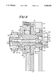
- FIG. 3 is a cross-section according to line III--III in FIG. 2, but for a different position;
- FIG. 4 shows a view similar to that in FIG. 3, but for another position
- FIG. 5 shows a cross-section, to a greater scale, according to line V--V in FIG. 3;
- FIGS. 6 and 7 represent the part shown in FIG. 5 in various positions.
- FIG. 1 is a schematic representation of a weaving machine having as main parts the warp beam 1, the warp 2, the back rest 3, the harnesses 4, the harness drive 5, the shed 6, the sley 7 with the reed 8, the formed cloth 9, the sand roller 10, the cloth beam 11 and the main drive motor 12.
- the back rest 3 is mounted on each end in a supporting mechanism 13 which is moved to and fro by means of a device 14.
- the movement of the back rest 3 is in this case periodical and synchronized with the movement of the harnesses 4.
- the driving wheel 15 of said device 14, which consists, for example, of a gear is coupled to the main shaft 16 of the weaving machine, for example by means of a gear 17 placed on it.
- the main shaft 16, for that matter, is coupled to the harness drive 5 in the known way via a transmission 18 with a transmission ratio of 1/2.
- the present invention is special in that the device 14, as shown in FIG. 3, is made up of the combination of the above-mentioned supporting mechanisms 13 in between which the back rest 3 has been mounted; at least one eccentric 19 to move the supporting mechanisms 13 and which has been provided with setting means 20 to modify the eccentricity; the above-mentioned driving wheel 15, which drives the eccentric 19; and driving means to drive said driving wheel 15, which consists, in this case, of the gear 17, the main shaft 16 and the main drive motor 12; whereby means 21 are provided in between the driving wheel 15 and the eccentric 19 which allow for a continuous setting of the phase of the eccentric in relation to the driving wheel 15.
- These means 21 mainly consist in this case of a smooth seating 22, centrically formed in the driving wheel 15, an element 23 which fits in the seating 22 and which can be turned around in relation to the driving wheel 15 to which the eccentric 19 has been attached, and clamping means which can clamp the turnable element 23 in the seating 22 according to any required angle position.
- the seating 22 is mounted directly in the driving wheel 15, and said seating 22 and the element 23 are conically shaped.
- the clamping means preferably consist of a bolt-shaped element 24, which is made up of a threaded end 25 which can be axially screwed in the narrowest end 26 of the conical element 23, a screw head 27 and a collar 28 which can operate in conjunction with the driving wheel 15 or any other support whatsoever, in such a way that the conical element 23 can be clamped in the seating 22 according to the set angle position as a result of the screwing of screw head 27.
- the collar 28 can also be formed by means of a washer.
- the eccentric 19 and the setting means 20 is arbitrary.
- the eccentric is made up of a pivot 32 designed to make the eccentric movement, and a claw coupling 33 between the pivot 32 and the above-mentioned element 23, whereby said claw coupling 33 is made such that its first coupling element 34 is placed in an eccentric position and is attached onto or is part of the element 23, whereas the second coupling element 35 is attached eccentrically to the pivot 32.
- the pivot 32 is attached onto the element 23 by means of a bolt 36 which moves freely through a bore hole 37 into the element 23 and which is screwed into the pivot 32 with its threaded end 38.
- Both the bore hole 37 and the bolt 36 are placed in an eccentric position in relation to the element 23, but in a centric position with relation to the coupling part 34 of the claw coupling 33.
- the bolt 36 is placed in an eccentric position in relation to the pivot 32, but in a centric position in relation to the coupling element 35 of the claw coupling 33.
- the head of the bolt 36 is countersunk under the bolt-shaped element 24.
- said bolt 36 has an internal hexagon 39 or something similar, while the bolt-shaped element 24 is provided with a bore hole 40 which makes the hexagon 39 accessible.
- the bolt 36 does not fit in this bore hole 40, however, and thus it cannot be taken out of the bore hole 37 without the bolt-shaped element 24 being removed.
- the above-mentioned supporting mechanisms 13 which convert the eccentrical movement of the eccentric 19 in a periodical movement of the back rest 3 may, of course, be of an arbitrary form.
- these supporting mechanisms 13 mainly consist of an arm 41 which is borne with one end around the pivot 32 and which is coupled with hinges at its other end to a second arm 42, which, in turn, is attached at its opposite end in a rotatable way to a support 44 attached onto the frame 43 of the weaving machine.
- the back rest 3 is preferably mounted on the arms 41 by means of elastic, bendable supports 45, each consisting of at least two parallel plate springs 46 and 47 which, at one end 48, are fixed onto the arm 41 and, at the other ends, are interconnected by means of an element 49 in which the shaft end 50 of the back rest 3 is mounted.
- the supports 45 may be arranged either horizontally as represented in FIG. 2 or in any other suitable direction.
- the driving wheel 15 is driven at the same speed as the main shaft 16 of the weaving machine.
- the working of the device 14 can be easily deduced from FIGS. 3 to 7.
- the pivot 32 moves around the axis of rotation 51 of the element 23 and the driving wheel 15, in particular according to a movement 52 as indicated in FIG. 2, with an eccentricity E.
- the eccentricity E in this case equals the distance between said axis of rotation 51 and the axial axis 53 of the pivot 32.
- the bolt 36 is unscrewed until a situation as represented in FIG. 4 is obtained, whereby the pivot 32 and the second coupling element 35 are pushed away from the first coupling element 34 as the head of the bolt 36 is prevented from making a notable axial movement due to the presence of the bolt-shaped element 24.
- the eccentricity E can then be modified by turning the second coupling element 35 of the claw coupling.
- the axis 53 makes a circular movement 54 as represented in FIG. 5, such that the eccentricity E can be set from zero to the maximum distance possible between the axis of rotation 51 and the axis 53.
- the claw coupling 33 is then closed again by screwing the bolt 36.
- the original phase can be easily reset by loosening the clamping means 24 and by turning the element 23 in the opposite sense in its seating 22, in particular until a situation as represented in FIG. 7 is obtained.
- the element 23 is then again clamped in the seating 22 by screwing the bolt-shaped element 24.
- the device 14 according to the invention also makes it possible to cause a phase shift between the eccentric 19 and the driving wheel 15 in the case of a modification of the mutual movement of the harnesses in relation to the main shaft of the weaving machine.
- the clamping means 24 merely have to be loosened, the element 23 has to be turned in its seating 22, and the clamping means 24 have to be tightened again.
- the device 14 allows for a continuous setting in this case, as the element 23 can be secured to the driving wheel 15 according to an arbitrary angle position.
- the device 14 according to the invention also allows for a phase shift according to any required value.
- the device 14 can be used in combination with any sort of eccentric, whereby this eccentric does not necessarily have to be mounted directly onto the element 23, and whereby said eccentric does not necessarily have to have an adjustable eccentricity.
Landscapes
- Engineering & Computer Science (AREA)
- Textile Engineering (AREA)
- Looms (AREA)
Abstract
A device for moving a back rest in weaving machines includes two movable supporting mechanisms between which the back rest is mounted, an eccentric for moving the supporting mechanisms and whose eccentricity can be modified, and a driving wheel for driving the eccentric. A mechanism provided between the driving wheel and the eccentric permits a continuous setting of the phase of the eccentric in relation to the driving wheel. The mechanism includes a seating formed in the driving wheel, an element which fits in the seating and which can be axially turned in relation to the driving wheel to which the eccentric is coupled, and a clamp for clamping the element at any required angular position in the seating.
Description
The present invention concerns a device for moving the back rest in weaving machines, in particular according to a periodical movement.
It is known that, in weaving machines, the back rest has to move to and fro in accordance with the harness motion, this in order to obtain that, in spite of the opening and closing of the shed, the warp tension remains practically the same. As known from U.S. Pat. No. 3,567,354, the required periodical movement to this end can be obtained by means of the connecting rods which are connected to the back rest and driven by the sley.
It is also known that said periodical movement of the back rest can be obtained by means of an eccentric, driven by the main shaft of the weaving machine. This known embodiment is usually also provided with adjusting means to set the eccentricity. The setting of the eccentricity may involve a phase shift between the movements made respectively by the harnesses and the back rest. It is obvious that the phase between said movements has to be reset.
In order to obtain that the warp tension remains practically the same in spite of the opening and closing of the shed, the movement of the back rest has to be more or less in phase with the opening and closing of the shed. It is known, however, that, depending on the cloth to be woven, the movement of the harnesses in relation to the movement of the sley or the main shaft of the weaving machine may be changed. In order to obtain, in case of such a change, that said movement of the back rest, which has been obtained by the movement of the main shaft, remains in phase with the opening and closing of the shed, also the phase between the main shaft and the movement of the back rest has to be set.
In the known embodiments, this is done by driving the eccentric by means of a gear wheel clutch, such that, through the release of these clutches and through the mutual turning of the gear wheels, the setting can be executed.
It is clear that this is a time-consuming method which does not allow for continuous setting.
The present invention concerns a device for moving the back rest in weaving machines which does not have the disadvantages of conventional phase setting devices, in other words, which has as an advantage that the setting of said phase is very simple and is not limited to a number of present values.
To this aim, the invention concerns a device for moving the back rest in weaving machines, in particular according to a periodical movement, consisting of two moveable supporting mechanisms in between which the back rest is mounted; at least one eccentric for moving the supporting mechanisms; a driving wheel to drive the eccentric; and driving means to drive the driving wheel; characterized in that means have been provided in between the driving wheel and the eccentric, allowing for a continuous setting of the phase of the eccentric in relation to the driving wheel, whereby said means consist of a seating connected to the driving wheel and placed in a centric position in relation to that driving wheel; an element which fits in the seating and which can be turned around in relation to said seating, and to which the eccentric is coupled; and clamping means which can clamp the turnable element in any required angle position in the seating.
In preference, the above-mentioned seating and the element which fits in it are conically shaped, whereas the clamping means consist of a bolt-shaped element which fastens the conical element axially in the seating as it is screwed.
In order to better explain the characteristics of the invention, by way of example only and without being limitative in any way, the following preferred embodiment is described with reference to the accompanying drawings, where:
FIG. 1 is a schematic representation of a weaving machine which uses the device according to the invention;
FIG. 2 shows a view of the part indicated in FIG. 1 as F2 to a greater scale;
FIG. 3 is a cross-section according to line III--III in FIG. 2, but for a different position;
FIG. 4 shows a view similar to that in FIG. 3, but for another position;
FIG. 5 shows a cross-section, to a greater scale, according to line V--V in FIG. 3;
FIGS. 6 and 7 represent the part shown in FIG. 5 in various positions.
FIG. 1 is a schematic representation of a weaving machine having as main parts the warp beam 1, the warp 2, the back rest 3, the harnesses 4, the harness drive 5, the shed 6, the sley 7 with the reed 8, the formed cloth 9, the sand roller 10, the cloth beam 11 and the main drive motor 12.
As shown in FIG. 2, the back rest 3 is mounted on each end in a supporting mechanism 13 which is moved to and fro by means of a device 14. The movement of the back rest 3 is in this case periodical and synchronized with the movement of the harnesses 4. To this aim, the driving wheel 15 of said device 14, which consists, for example, of a gear, is coupled to the main shaft 16 of the weaving machine, for example by means of a gear 17 placed on it. The main shaft 16, for that matter, is coupled to the harness drive 5 in the known way via a transmission 18 with a transmission ratio of 1/2.
The present invention is special in that the device 14, as shown in FIG. 3, is made up of the combination of the above-mentioned supporting mechanisms 13 in between which the back rest 3 has been mounted; at least one eccentric 19 to move the supporting mechanisms 13 and which has been provided with setting means 20 to modify the eccentricity; the above-mentioned driving wheel 15, which drives the eccentric 19; and driving means to drive said driving wheel 15, which consists, in this case, of the gear 17, the main shaft 16 and the main drive motor 12; whereby means 21 are provided in between the driving wheel 15 and the eccentric 19 which allow for a continuous setting of the phase of the eccentric in relation to the driving wheel 15. These means 21 mainly consist in this case of a smooth seating 22, centrically formed in the driving wheel 15, an element 23 which fits in the seating 22 and which can be turned around in relation to the driving wheel 15 to which the eccentric 19 has been attached, and clamping means which can clamp the turnable element 23 in the seating 22 according to any required angle position.
In preference, the seating 22 is mounted directly in the driving wheel 15, and said seating 22 and the element 23 are conically shaped.
The clamping means preferably consist of a bolt-shaped element 24, which is made up of a threaded end 25 which can be axially screwed in the narrowest end 26 of the conical element 23, a screw head 27 and a collar 28 which can operate in conjunction with the driving wheel 15 or any other support whatsoever, in such a way that the conical element 23 can be clamped in the seating 22 according to the set angle position as a result of the screwing of screw head 27. It is clear that the collar 28 can also be formed by means of a washer.
It is clear that the driving wheel 15 and the element 23 have to be borne in an appropriate way, for example as indicated, by means of bearings 29 and 30 mounted in a housing 31.
The nature of the eccentric 19 and the setting means 20 is arbitrary. According to the embodiment described in FIG. 3, the eccentric is made up of a pivot 32 designed to make the eccentric movement, and a claw coupling 33 between the pivot 32 and the above-mentioned element 23, whereby said claw coupling 33 is made such that its first coupling element 34 is placed in an eccentric position and is attached onto or is part of the element 23, whereas the second coupling element 35 is attached eccentrically to the pivot 32. The pivot 32 is attached onto the element 23 by means of a bolt 36 which moves freely through a bore hole 37 into the element 23 and which is screwed into the pivot 32 with its threaded end 38. Both the bore hole 37 and the bolt 36 are placed in an eccentric position in relation to the element 23, but in a centric position with relation to the coupling part 34 of the claw coupling 33. The bolt 36 is placed in an eccentric position in relation to the pivot 32, but in a centric position in relation to the coupling element 35 of the claw coupling 33.
The head of the bolt 36 is countersunk under the bolt-shaped element 24. In order to be able to turn the bolt 36 without having to remove the bolt-shaped element 24, said bolt 36 has an internal hexagon 39 or something similar, while the bolt-shaped element 24 is provided with a bore hole 40 which makes the hexagon 39 accessible. The bolt 36 does not fit in this bore hole 40, however, and thus it cannot be taken out of the bore hole 37 without the bolt-shaped element 24 being removed.
The above-mentioned supporting mechanisms 13 which convert the eccentrical movement of the eccentric 19 in a periodical movement of the back rest 3 may, of course, be of an arbitrary form. In preference, use is to be made of a construction as represented in FIG. 2, in which these supporting mechanisms 13 mainly consist of an arm 41 which is borne with one end around the pivot 32 and which is coupled with hinges at its other end to a second arm 42, which, in turn, is attached at its opposite end in a rotatable way to a support 44 attached onto the frame 43 of the weaving machine.
The back rest 3 is preferably mounted on the arms 41 by means of elastic, bendable supports 45, each consisting of at least two parallel plate springs 46 and 47 which, at one end 48, are fixed onto the arm 41 and, at the other ends, are interconnected by means of an element 49 in which the shaft end 50 of the back rest 3 is mounted. The supports 45 may be arranged either horizontally as represented in FIG. 2 or in any other suitable direction.
It should be noted that the driving wheel 15 is driven at the same speed as the main shaft 16 of the weaving machine.
The working of the device 14 can be easily deduced from FIGS. 3 to 7.
In the position according to FIG. 3, as the driving wheel 15 rotates, the pivot 32 moves around the axis of rotation 51 of the element 23 and the driving wheel 15, in particular according to a movement 52 as indicated in FIG. 2, with an eccentricity E. The eccentricity E in this case equals the distance between said axis of rotation 51 and the axial axis 53 of the pivot 32.
When the eccentricity E is modified, the bolt 36 is unscrewed until a situation as represented in FIG. 4 is obtained, whereby the pivot 32 and the second coupling element 35 are pushed away from the first coupling element 34 as the head of the bolt 36 is prevented from making a notable axial movement due to the presence of the bolt-shaped element 24.
The eccentricity E can then be modified by turning the second coupling element 35 of the claw coupling. As the coupling elements 34 and 35 are readjusted in relation to each other, the axis 53, however, makes a circular movement 54 as represented in FIG. 5, such that the eccentricity E can be set from zero to the maximum distance possible between the axis of rotation 51 and the axis 53. The claw coupling 33 is then closed again by screwing the bolt 36.
It is clear that the setting of a different eccentricity as described above also results in a phase shift F, as is shown in FIGS. 5 and 6, which represent a view before and after the modification of the eccentricity respectively, whereby H represents the rotation of the second coupling element 35 in relation to the first coupling element 34.
According to the present invention, the original phase can be easily reset by loosening the clamping means 24 and by turning the element 23 in the opposite sense in its seating 22, in particular until a situation as represented in FIG. 7 is obtained. The element 23 is then again clamped in the seating 22 by screwing the bolt-shaped element 24.
The device 14 according to the invention also makes it possible to cause a phase shift between the eccentric 19 and the driving wheel 15 in the case of a modification of the mutual movement of the harnesses in relation to the main shaft of the weaving machine. In this case, the clamping means 24 merely have to be loosened, the element 23 has to be turned in its seating 22, and the clamping means 24 have to be tightened again.
It is clear that the device 14 allows for a continuous setting in this case, as the element 23 can be secured to the driving wheel 15 according to an arbitrary angle position.
The device 14 according to the invention, for reasons other than those mentioned above, also allows for a phase shift according to any required value.
It is also clear that the device 14 can be used in combination with any sort of eccentric, whereby this eccentric does not necessarily have to be mounted directly onto the element 23, and whereby said eccentric does not necessarily have to have an adjustable eccentricity.
The present invention is in no way limited to the embodiments described by way of example and shown in the accompanying drawings; on the contrary, such a device for moving the back rest in weaving machines can be made in various forms and dimensions while still remaining within the scope of the invention.
Claims (13)
1. A device for periodically moving a back rest in a weaving machine, comprising:
means for supporting the back rest including two moveable supporting mechanisms between which the back rest is mounted; means including at least one eccentric member for moving the supporting mechanisms; drive means including a driving wheel for driving the eccentric member; driving means for driving the driving wheel; and continuous phase setting means between the driving wheel and the eccentric member for continuously setting the phase of the eccentric member in relation to the driving wheel, said continuous phase setting means comprising a seating connected to the driving wheel in a centric position relative to the driving wheel; a turnable element rotatably fitted in the seating and coupled to the eccentric member; and clamping means for clamping the turnable element in any required angular position in relation to said seating.
2. A device as claimed in claim 1, wherein said turnable element and said seating are conically shaped.
3. A device as claimed in claim 1, wherein the clamping means comprises means including a bolt-shaped element axially screwed in the turnable element for fastening the turnable element in said seating.
4. A device as claimed in claim 3, wherein the bolt-shaped element comprises a collar which rests on a side flank of the seating when the bolt-shaped element is axially screwed into the turnable element.
5. A device as claimed in claim 1, wherein the eccentric member comprises eccentricity setting means for modifying the eccentricity of the eccentric member.
6. A device as claimed in claim 1, wherein the eccentric member comprises a pivot and said supporting mechanisms are mounted on said pivot, and said eccentric member also comprises a claw coupling placed in between said pivot and said turnable element, said claw coupling comprising a first coupling element mounted eccentrically onto the turnable element and a second coupling element on which said pivot is mounted, said second coupling element and said pivot being mounted eccentrically in relation to each other.
7. A device as claimed in claim 6, comprising means including a bolt for tightening the claw coupling, said bolt passing through the turnable element and being situated parallel to an axis of rotation of the turnable element and centric in relation to said claw coupling.
8. A device as claimed in claim 7, wherein the clamping means comprise a bolt-shaped element, and wherein said bolt is countersunk under the bolt-shaped element, said bolt-shaped element comprising means including a bore hole for providing access to a head of said bolt such that the claw coupling can be loosened by turning the head, the bolt-shaped element preventing the bolt from axially shifting.
9. A device as claimed in claim 1, wherein the driving wheel comprises a gear coupled to a main shaft of the weaving machine and having the same speed of revolution as the main shaft.
10. A device as claimed in claim 9, wherein said seating is formed directly in said gear.
11. A device as claimed in claim 1, wherein each of the supporting mechanisms comprises an arm connected to the eccentric member at one end and rotatably coupled to a second arm at a second end, said second arm being rotatably mounted at an end thereof to a frame of the weaving machine.
12. A device as claimed in claim 11, further comprising means including elastic supports for mounting the back rest on said support mechanisms.
13. A device as claimed in claim 12, wherein each of said elastic supports comprises at least two parallel plate springs fixed at one end to said supporting mechanisms, and connected with each other at a second end to provide support for the back rest.
Applications Claiming Priority (2)
| Application Number | Priority Date | Filing Date | Title |
|---|---|---|---|
| BE8900779A BE1004382A3 (en) | 1989-07-17 | 1989-07-17 | Device for moving the trail at looms. |
| BE8900779 | 1989-07-17 |
Publications (1)
| Publication Number | Publication Date |
|---|---|
| US5044408A true US5044408A (en) | 1991-09-03 |
Family
ID=3884252
Family Applications (1)
| Application Number | Title | Priority Date | Filing Date |
|---|---|---|---|
| US07/552,560 Expired - Fee Related US5044408A (en) | 1989-07-17 | 1990-07-16 | Device for moving the back rest in weaving machines |
Country Status (4)
| Country | Link |
|---|---|
| US (1) | US5044408A (en) |
| EP (1) | EP0409306A1 (en) |
| JP (1) | JPH03137250A (en) |
| BE (1) | BE1004382A3 (en) |
Cited By (3)
| Publication number | Priority date | Publication date | Assignee | Title |
|---|---|---|---|---|
| US5558132A (en) * | 1994-07-30 | 1996-09-24 | Lindauer Dornier Gesellschaft Mbh | Adjustable warp tension roll support in a weaving loom |
| US20110132488A1 (en) * | 2009-12-04 | 2011-06-09 | Taiwan Textile Research Institute | Weaving machines and three-dimensional woven fabrics |
| US20120227855A1 (en) * | 2009-12-04 | 2012-09-13 | Taiwan Textile Research Institute | Weaving machines and three-dimensional woven fabrics |
Families Citing this family (8)
| Publication number | Priority date | Publication date | Assignee | Title |
|---|---|---|---|---|
| BE1004624A3 (en) * | 1990-11-22 | 1992-12-22 | Picanol Nv | SUPPORT DEVICE FOR TRAIL in a weaving machine. |
| DE4427129C2 (en) * | 1994-07-30 | 1998-07-30 | Dornier Gmbh Lindauer | Tensioning unit for the weaving chain of a weaving machine |
| EP0937796A1 (en) * | 1998-02-18 | 1999-08-25 | Sulzer Rüti Ag | Warp threads tensioning device for a loom and loom with such a device |
| DE19856308B4 (en) * | 1998-12-07 | 2005-02-24 | Lindauer Dornier Gmbh | Method for compensating the elongation or tension change in a warp and loom for performing the method |
| DE19915952A1 (en) * | 1998-12-07 | 2000-10-12 | Dornier Gmbh Lindauer | Improved method for compensating the change in elongation or tension in a warp and weaving machine to carry out the method |
| DE10159236C1 (en) * | 2001-12-03 | 2003-10-09 | Dornier Gmbh Lindauer | Loom for weaving leno fabrics has an additional guide rod for the leno warps, at the back rest roller for the band of warps, to give an independent tension adjustment from the standing warps as the shed changes |
| CN102146609A (en) * | 2010-11-13 | 2011-08-10 | 江苏万工科技集团有限公司 | Rear beam driving mechanism of jet loom |
| CN102409473A (en) * | 2011-09-26 | 2012-04-11 | 江苏万工科技集团有限公司 | Three-gear sliding block warp loosening mechanism |
Citations (4)
| Publication number | Priority date | Publication date | Assignee | Title |
|---|---|---|---|---|
| US3072153A (en) * | 1959-02-06 | 1963-01-08 | Fieldcrest Mills Inc | Method and apparatus for weaving variant-height-loop terry fabrics |
| US3552447A (en) * | 1969-06-04 | 1971-01-05 | North American Rockwell | Loom let-off |
| US3567354A (en) * | 1967-09-20 | 1971-03-02 | Strake Maschf Nv | Apparatus for controlling the warp tension in a weaving machine |
| US4256147A (en) * | 1978-07-24 | 1981-03-17 | Saurer - Diederichs Societe Anonyme | Weaving loom |
-
1989
- 1989-07-17 BE BE8900779A patent/BE1004382A3/en not_active IP Right Cessation
-
1990
- 1990-07-03 EP EP90201780A patent/EP0409306A1/en not_active Withdrawn
- 1990-07-16 US US07/552,560 patent/US5044408A/en not_active Expired - Fee Related
- 1990-07-17 JP JP2189266A patent/JPH03137250A/en active Pending
Patent Citations (4)
| Publication number | Priority date | Publication date | Assignee | Title |
|---|---|---|---|---|
| US3072153A (en) * | 1959-02-06 | 1963-01-08 | Fieldcrest Mills Inc | Method and apparatus for weaving variant-height-loop terry fabrics |
| US3567354A (en) * | 1967-09-20 | 1971-03-02 | Strake Maschf Nv | Apparatus for controlling the warp tension in a weaving machine |
| US3552447A (en) * | 1969-06-04 | 1971-01-05 | North American Rockwell | Loom let-off |
| US4256147A (en) * | 1978-07-24 | 1981-03-17 | Saurer - Diederichs Societe Anonyme | Weaving loom |
Cited By (7)
| Publication number | Priority date | Publication date | Assignee | Title |
|---|---|---|---|---|
| US5558132A (en) * | 1994-07-30 | 1996-09-24 | Lindauer Dornier Gesellschaft Mbh | Adjustable warp tension roll support in a weaving loom |
| US20110132488A1 (en) * | 2009-12-04 | 2011-06-09 | Taiwan Textile Research Institute | Weaving machines and three-dimensional woven fabrics |
| US8015999B2 (en) * | 2009-12-04 | 2011-09-13 | Taiwan Textile Research Institute | Weaving machines and three-dimensional woven fabrics |
| US20110265906A1 (en) * | 2009-12-04 | 2011-11-03 | Taiwan Textile Research Institute | Weaving machines and three-dimensional woven fabrics |
| US20120227855A1 (en) * | 2009-12-04 | 2012-09-13 | Taiwan Textile Research Institute | Weaving machines and three-dimensional woven fabrics |
| US8286668B2 (en) * | 2009-12-04 | 2012-10-16 | Taiwan Textile Research Institute | Weaving machines and three-dimensional woven fabrics |
| US8662112B2 (en) * | 2009-12-04 | 2014-03-04 | Taiwan Textile Research Institute | Weaving machines and three-dimensional woven fabrics |
Also Published As
| Publication number | Publication date |
|---|---|
| BE1004382A3 (en) | 1992-11-10 |
| JPH03137250A (en) | 1991-06-11 |
| EP0409306A1 (en) | 1991-01-23 |
Similar Documents
| Publication | Publication Date | Title |
|---|---|---|
| US5044408A (en) | Device for moving the back rest in weaving machines | |
| DE3854613T2 (en) | Belt tensioner with detachable belt tension damper. | |
| DE69416212T2 (en) | Fuel gas supply system for an internal combustion engine of a vehicle | |
| DE3906510C2 (en) | ||
| US4479734A (en) | Adjusting mechanism for position-adjustable connected structural parts, especially a driving-belt tension mechanism with a clamping coverplate | |
| US4470183A (en) | Roll construction | |
| US4784005A (en) | Crank drive having four spacially extending axes intersecting in one point | |
| US2859630A (en) | Motion transmitting mechanism | |
| US2627188A (en) | Crank arm adjustable in length and angular position | |
| DE2529949B2 (en) | Motor vehicle windshield wipers | |
| DE102017118233A1 (en) | Ring tensioner with tensioning roller-positioning adjustment means | |
| JPH0543111Y2 (en) | ||
| KR100566521B1 (en) | Tension Roller for Twisting Machine | |
| US6311607B1 (en) | Device for altering the displacement volume of a hydrostatic machine | |
| DE3623016C1 (en) | Shuttleless weaving machine for the single-shot production of double-pile fabric | |
| DE68909263T2 (en) | Weft thread store for weaving machines. | |
| JPH04228645A (en) | Assembling method of operating member of rotating dobby machine, this operating member and rotating dobby machine equipped with this operating member | |
| US4036266A (en) | Take-up motion for looms | |
| DE69325724T2 (en) | VIBRATION SCREEN | |
| DE2940875A1 (en) | Belt driven vehicle dynamo mounting - has single adjusting nut for setting belt tension | |
| DE2339854C2 (en) | Device for the automatic control of the headlight range of motor vehicle headlights | |
| DE4301850A1 (en) | Automatic mechanical transmission belt tensioning system | |
| CN209340432U (en) | A kind of strainer and transmission device | |
| DE9417388U1 (en) | Locking mechanism for the lid of a laboratory centrifuge | |
| JPH10130986A (en) | Opening apparatus in weaving machine |
Legal Events
| Date | Code | Title | Description |
|---|---|---|---|
| AS | Assignment |
Owner name: PICANOL N.V., BELGIUM Free format text: ASSIGNMENT OF ASSIGNORS INTEREST.;ASSIGNORS:VANDEWEGHE, MICHEL;LEFEVER, BART;VANDERSYPPE, STEFAAN;REEL/FRAME:005421/0571 Effective date: 19900608 |
|
| REMI | Maintenance fee reminder mailed | ||
| LAPS | Lapse for failure to pay maintenance fees | ||
| FP | Lapsed due to failure to pay maintenance fee |
Effective date: 19950906 |
|
| STCH | Information on status: patent discontinuation |
Free format text: PATENT EXPIRED DUE TO NONPAYMENT OF MAINTENANCE FEES UNDER 37 CFR 1.362 |