US5042602A - Loader - Google Patents
Loader Download PDFInfo
- Publication number
- US5042602A US5042602A US07/568,890 US56889090A US5042602A US 5042602 A US5042602 A US 5042602A US 56889090 A US56889090 A US 56889090A US 5042602 A US5042602 A US 5042602A
- Authority
- US
- United States
- Prior art keywords
- fore
- engine room
- radiator
- engine
- disposed
- Prior art date
- Legal status (The legal status is an assumption and is not a legal conclusion. Google has not performed a legal analysis and makes no representation as to the accuracy of the status listed.)
- Expired - Lifetime
Links
Images


Classifications
-
- E—FIXED CONSTRUCTIONS
- E02—HYDRAULIC ENGINEERING; FOUNDATIONS; SOIL SHIFTING
- E02F—DREDGING; SOIL-SHIFTING
- E02F9/00—Component parts of dredgers or soil-shifting machines, not restricted to one of the kinds covered by groups E02F3/00 - E02F7/00
- E02F9/08—Superstructures; Supports for superstructures
- E02F9/0858—Arrangement of component parts installed on superstructures not otherwise provided for, e.g. electric components, fenders, air-conditioning units
- E02F9/0866—Engine compartment, e.g. heat exchangers, exhaust filters, cooling devices, silencers, mufflers, position of hydraulic pumps in the engine compartment
-
- B—PERFORMING OPERATIONS; TRANSPORTING
- B60—VEHICLES IN GENERAL
- B60K—ARRANGEMENT OR MOUNTING OF PROPULSION UNITS OR OF TRANSMISSIONS IN VEHICLES; ARRANGEMENT OR MOUNTING OF PLURAL DIVERSE PRIME-MOVERS IN VEHICLES; AUXILIARY DRIVES FOR VEHICLES; INSTRUMENTATION OR DASHBOARDS FOR VEHICLES; ARRANGEMENTS IN CONNECTION WITH COOLING, AIR INTAKE, GAS EXHAUST OR FUEL SUPPLY OF PROPULSION UNITS IN VEHICLES
- B60K11/00—Arrangement in connection with cooling of propulsion units
- B60K11/02—Arrangement in connection with cooling of propulsion units with liquid cooling
- B60K11/04—Arrangement or mounting of radiators, radiator shutters, or radiator blinds
Definitions
- the present invention relates to a loader such as a construction loader, an agriculture loader and the like, but which has a cab and an engine room arranged in the fore and rear direction of its body, in order from the foreside, as well as a working attachment disposed in its fore space outside the body, and more specifically to a cooling system which accommodates a liquid-cooled internal combustion engine, a radiator for cooling an engine cooling liquid, a radiator for cooling a working oil and a cooling fan within the engine room and is adapted to cool both the radiators with the cooling air flow produced by the cooling fan.
- radiator cooling system has been known the ones disclosed in Japanese Laid Open Utility Model Publication No. 1986-106429 (refer to as a first conventional embodiment hereinafter) and in U.S. Pat. No. 4,815,550 (Mather et al.) (refer to as a second conventional embodiment hereinafter).
- a deep rear door is so pivotally disposed as to open and close a rear maintenance opening on the rear side of an engine room.
- a radiator for cooling an engine cooling liquid and a radiator for cooling a working oil are arranged in order from the foreside within the space inside of the rear door and supported by means of the rear door.
- An axial fan is so disposed as to face the radiator for cooling the engine cooling liquid from the foreside.
- the rear door Since there are arranged two radiators in series, the rear door largely projects rearwards so that the rear portion of the loader body largely overhangs. Therefore, the total length of the body becomes longer by the overhanging distance.
- the working oil cooling radiator is disposed between the engine cooling liquid cooling radiator and the rear panel of the rear door, it is difficult to visually notice a clogged condition of the radiator in case that it is clogged by foreign substances such as dusts, straw debris and the like. Therefore, the working oil tends to overheat. When the cleaning of the working oil cooling radiator is carried out, it is necessary to previously dismount the engine cooling liquid cooling radiator from the rear door. As a result, it takes much labor.
- a bonnet In the upper space of an engine room on the rear side of a cab there are arranged a bonnet, a working oil cooling radiator, an engine cooling liquid cooling radiator and a radial cooling fan in order from above.
- a cooling air sucked through an air induction port of the bonnet is adapted to flow through the working oil cooling radiator and the engine cooling liquid cooling radiator in order and then to be discharged from an air discharge port of a rear door.
- the engine cooling liquid cooling radiator is disposed in the deep portion of the engine room below the working oil cooling radiator, it is difficult to visually notice its clogged condition in case that it is clogged by foreign substances. Therefore, the engine cooling liquid tends to overheat. When the engine cooling liquid cooling radiator is cleaned, it is necessary to previously dismount the working oil cooling radiator from the body. As a result, it takes much labor.
- the two radiators and the cooling fan are arranged in a pile above the engine, the upper portion of the engine room can't help projecting upward. Therefore, the rearward field of vision from the cab becomes bad.
- the loader according to the present invention is constructed as follows.
- the first invention is constructed as follows.
- a liquid-cooled internal combustion engine, a first radiator for cooling a engine cooling liquid, a cooling fan, a fan driving means and a second radiator for cooling a working oil are accommodated within an engine room partitioned from an outside space by means of an engine room wall.
- An upper maintenance opening is formed in the upper portion of the engine room wall, and a rear maintenance opening is formed in the rear portion thereof.
- the upper maintenance opening is so covered as to be opened and closed by an upper cover member provided with an air induction port.
- the rear opening is so covered as to be opened and closed by a rear cover member provided with an air discharge port.
- One of both radiators is so disposed as to face the rear maintenance opening, and the other thereof is so disposed as to face the upper maintenance opening.
- the cooling fan By operating the cooling fan by means of the fan driving means, the air within the upper portion of the engine room is sucked into the engine room through the air induction port so as to pass along the other radiator, the cooling fan and one radiator in order and is finally discharge outside the engine room from the air discharge port of the rear cover member.
- the thickness dimension of the rear cover member in the fore and rear direction can be small by that portion. Therefore, an overhang of the rear portion of the loader body can be small and the total length of the body can be shortened.
- the first radiator for cooling the engine cooling liquid is so disposed as to face the rear maintenance opening and the second radiator for cooling the working oil is so disposed as to face the upper maintenance opening, the following advantage can be provided. That is, since a fresh outside air is supplied to the second radiator, the cooling efficiency is high and it is possible to make the radiator smaller in dimension.
- the second invention is constructed as follows.
- a cab disposed in the foreside portion of the loader body is so supported by the body as to be changed over between a driving position in which the cab is pivoted forward and downward and a maintenance position in which the cab is pivoted backward and upward.
- An engine room disposed in the rear portion of the body is partitioned from the outside space by means of an engine room wall and accommodates a liquid-cooled internal combustion engine, a first radiator for cooling an engine cooling liquid and an air cleaner.
- a fore maintenance opening is formed in the fore wall portion of the engine room. The fore maintenance opening is so covered as to be opened and closed by means of a rear wall member of the cab.
- An air induction pipe of the air cleaner is fixedly secured at its inlet portion to the body.
- An intake muffler to be connected to the air cleaner is fixedly secured to a pivoting portion of the cab.
- the intake muffler is air-tightly connected at its outlet portion with the inlet portion of the air induction pipe so as to intercommunicate with each other.
- the cab is changed over to the maintenance position on the rear and upper side, the intercommunication between the outlet portion of the intake muffler and the inlet portion of the air induction pipe is cancelled.
- the intake muffler for reducing the intake noise of the engine is disposed in the space outside the engine room, it becomes possible to make the remarkable reduction of the intake noise by provision of the muffling chamber having a large capacity compatible with the compaction of the engine room.
- the third invention is constructed as follows.
- a loader is of the skid steer type.
- a cab is disposed in the foreside portion of a loader body, and an engine room is disposed in the rear portion thereof.
- a hydraulic transmission room is disposed in the space below the cab.
- the cab is provided with a lower surface member, a rear surface member and a seat to be fixedly secured to the lower surface member and is so supported as to be changed over between the driving position in which it is pivoted forward and downward and the maintenance position in which it is pivoted rearward and upward.
- a liquid-cooled internal combustion engine In the engine room partitioned from the outside space by means of an engine room wall there are provided a liquid-cooled internal combustion engine, a first radiator for cooling an engine cooling liquid, a cooling fan, a fan driving means and a second radiator for cooling a working oil.
- An upper maintenance opening formed in the upper portion of the engine room wall is so covered as to be opened and closed by means of an upper cover member.
- a rear maintenance opening formed in the rear portion of the engine room wall is so covered as to be opened and closed by means of a rear cover member.
- a fore maintenance opening formed in the fore portion of the engine room wall is so covered as to be opened and closed by means of a rear surface member of the cab.
- a maintenance opening for the hydraulic transmission room partitioned from the outside space by means of a transmission room wall is formed at least in the upper portion of the transmission room wall and is so covered as to be opened and closed by means of the lower surface member of the cab.
- FIGS. 1 through 10 show one embodiment of the present invention
- FIG. 1 is a perspective view of a loader
- FIG. 2 is a side view of the loader
- FIG. 3 is a back view of the loader
- FIG. 4 is a vertical sectional side view of a principal portion of the loader
- FIG. 5 is a horizontal sectional plan view of a principal portion of the loader
- FIG. 6 is a sectional view along VI--VI directed line in FIG. 4;
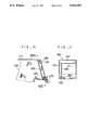
- FIG. 7 is a partial plan view of the rear portion of the loader
- FIG. 8 is a sectional view along VIII--VIII directed line in FIG. 4;
- FIG. 9 is a view showing a maintenance position of the loader corresponding to FIG. 4.
- FIG. 10 is a perspective view of a schematic construction of the loader body
- FIGS. 11 through 17 show a plurality of variants of the aforementioned embodiment
- FIGS. 11 and 12 shows a first variant
- FIG. 11 is a partial view corresponding to FIG. 4 and a vertical sectional side view of the rear portion of the loader;
- FIG. 12 is a partial sectional plan view of FIG. 11;
- FIGS. 13 through 15 show a second variant
- FIG. 13 is a view corresponding to FIG. 4;
- FIG. 14 a perspective view of the rear portion of a cab
- FIG. 15 is a sectional view along XV--XV directed line in FIG. 13;
- FIGS. 16 and 17 show a third variant
- FIG. 16 is a partial view corresponding to FIG. 13.
- FIG. 17 is a sectional view along XVII--XVII directed line in FIG. 16.
- FIGS. 1 through 10 show one embodiment of the present invention.
- the present invention is applied to a skid steer loader shown in the aforementioned U.S. Pat No. 4,815,550.
- the skid steer loader 1 comprises a body 2 supported by a pair of front wheels 3, 3 and a pair of rear wheels 4, 4.
- the symbols F and B designate a foreside and a rear side respectively
- the symbols L and R disignate a left side and a rignt side with respect to the advancing direction respectively.
- the body 2 comprises a pair of left and right main frames 6, 6 and boom-supporting frames 7, 7 projected upward from the rear portions of the respective main frames 6, 6 (refer to FIG. 10).
- a cab 8 is disposed in the space between both the main frames 6, 6 on the foreside of the body 2.
- the cab 8 is provided with a driver seat 9 and a head guard 10 covering the seat 9.
- the head guard 10 comprises left and right guard members 11, 11 and a ceiling member 12, and its full front portion and its rear upper portion are openable.
- a window 13 of each guard member 11 is covered with a wire gauze 14.
- An engine room 16 (herein, not illustrated) is formed in the rear portion of the body 2 so as to cover both the space between the respective rear portions of the paired main frames 6, 6 and the space between the paired boom-supporting frames 7, 7.
- a rear cover member 49 and an upper cover member 55 are opened as well as the cab 8 is pivoted to the maintenance position on the rear upper side at the time of maintenance, the engine room 16 is adapted to allow various machines and appliances therewithin readily to be accessed.
- a hydraulic working device 20 is constructed as follows.
- Booms 21, 21 are supported at their rear ends by the upper portions of the respective boom-supporting frames 7, 7 through pivot pins 22, 22 and are adapted to be actuated by means of hydraulic cylinders 23, 23 so as to be vertically raised and lowered.
- a bucket 24 as a working attachment is supported by the front portions of the booms 21 through pivot pins 25, 25 and is actuated by means of hydraulic cylinders 26, 26 so as to be vertically pivoted. Thereby, the bucket 24 is supported in such a manner as forward projecting in front of the body 2.
- the cab 8 comprises a lower surface member 31 provided with a lower surface plate 31a and a rear surface member 32 provided with a reversed-L shaped rear surface plate 32a which are fixedly secured between the left and right guard members 11, 11 and has the seat 9 fixed to the upper surface of the lower surface plate 31a.
- the cab 8 is vertically pivotally supported at its rear pivoted portions 33, 33 by the body 2 through pivot pins 34, 34 so as to be able to be changed over between the driving position A (refer to FIG. 4 ) in which it is fixedly secured to the body 2 by means of a fixing member 36 in the forward-pivoted state and the maintenance position C (refer to FIG. 9) in which it is pivoted to the rear upper side after cancellation of the secured condition of the fixing member 36.
- the cab 8 is held in the maintenance position C by means of extended gas cylinder 37.
- an engine room wall 40 which partitions the engine room 16 from the outside space comprises an upper wall portion 41, a lower wall portion 42, a left wall portion 43, a right wall portion 44, a fore wall portion 45 and a rear wall portion 46.
- a rear maintenance opening 48 formed in the rear wall portion 46 is so covered as to be opened and closed by means of the rear cover member 49 provided with a plurality of slit-like air-discharge ports 50.
- the rear cover member 49 is supported by the right side of the rear wall portion 46 through a hinge 51 pivotally in the fore and rear direction and is adapted to be brought into air-tight contact with the peripheral edge of the rear maintenance opening 48 through a gasket 52.
- the upper cover member 55 comprises an upper surface plate 56 provided with a plurality of slit-like air-induction ports 57 and a lower surface plate 58 provided with a rectangular through-hole 59 and has a sound-absorbing chamber 60 formed between both these plates 56, 58.
- the upper surface plate 56 is vertically pivotally mounted at its fore portion to the upper wall portion 41 through a hinge 61 and is adapted to be brought into air-tight contact with the peripheral edge of the upper maintenance opening 54 through a gasket 62.
- a sound-absorbing material (not illustrated) is attached to the inner surrounding surfaces of the upper surface plate 56 and the lower surface plate 58.
- a fore maintenance opening 64 is formed in the fore wall portion 45 in the inclined and forward facing manner and is so covered as to be opened an closed by means of a cover plate 32b fixedly secured to the rear side of the rear surface plate 32a of the cab 8.
- the rear surface plate 32 of the cab 8 is composed of both theses plates 32a, 32b.
- the cover plate 32b is adapted to be brought into air-tight contact with the peripheral edge of the fore maintenance opening 64 through a gasket 66.
- a liquid-cooled vertical diesel engine 70 whose crankshaft 71 extends in the fore and rear direction.
- the engine 70 is supported by the engine room wall 40 through four pieces of vibro-isolating rubbers 72.
- An air cleaner 74 is disposed in the upper portion of the left space outside the engine 70 so as to extend in the fore and rear direction.
- a connection pipe 76 as an inlet portion of an air induction pipe 75 of the air cleaner 74 is fixedly secured to the upper wall portion 41 of the engine room wall 40 by means of a bracket 77.
- the connection pipe 76 and the air cleaner 74 are connected to each other by means of a rubber hose 78.
- a resonance type intake muffler 80 is fixedly secured to the upper side of the cover plate 32b on the foreside of the pivoted portion 33 of the cab 8 corresponding to the connection pipe 76. As shown in FIGS.
- the intake muffler 80 comprises the muffling chamber 81 having a trapezoidal cross section, a louver type inlet portion 82 formed in the right wall of the chamber and a round outlet portion 83 formed in the fore wall thereof intercommunicated with each other.
- the outlet portion 83 of the intake muffler 80 is air-tightly connected in communication with the connection pipe 76 through a gasket 84.
- the communication between the outlet portion 83 of the intake muffler 80 and the connection pipe 76 is cancelled. Since the intake muffler 80 is disposed outside the engine room 16, it can have a large capacity easily. As a result, the intake noise can be sufficiently reduced.
- An exhaust muffler 86 is disposed in a midway height portion of the right space outside the engine 70 so as to extend in the fore and rear direction and is supported by the engine 70.
- a discharge portion of a muffler exhaust pipe 87 at its rear end is inserted into a through hole 49a of the rear cover member 49.
- first radiator 89 for cooling an engine cooling liquid and an axial cooling fan 90 in order from rear side.
- the first radiator 89 is so disposed as to face the rear maintenance opening 48.
- a forward projecting input shaft 91 of the cooling fan 90 is interlocking connected to the rear portion of the crankshaft 71 of the engine 70 through a wrapping connector type fan driving means 92 (herein, a belt transmission means).
- a make-up tank 94 for the engine cooling liquid is disposed on the right upper side of the first radiator 89, and a battery 95 is disposed on the lower side of the first radiator 89.
- a fuel tank 96 and a working oil tank 97 are disposed on both the right and left sides of the engine room 16 respectively. That is, liquid-tight space 98, 99 are formed outside the respective rear portions of both the main frames 6, 6 in the right and left direction respectively so that an engine fuel can be stored in the left liquid-tight space 98 and a working oil for a hydraulic working device 20 and a hydraulic transmission 101 can be stored in the right liquid-tight space 99.
- a hydraulic transmission room 102 is disposed in the space between the fore portions of both the main frames 6. 6 and below the cab 8 and is partitioned from the outside space by means of a transmission room wall 103.
- the hydraulic transmission room 102 and the engine room 16 are air-tightly partitioned by means of a removable partition wall 105 through a gasket 106.
- a maintenance opening 108 of the hydraulic transmission room 102 comprises an upper opening 109 and a fore opening 110 formed in the transmission room wall 103. Both these openings 109, 110 are so covered as to be opened and closed by means of the lower surface plate 31a of the cab 8 and the cover plate 31b projected from the fore portion of the lower surface plate 31a. Both these plates 31a, 31b are brought into air-tight contact with the peripheral edge of the maintenance opening 108 through a gasket 113.
- hydraulic pumps 115, 115 for moving the loader 1 and one working hydraulic pump 116 in order from behind.
- These hydraulic pumps are positive displacement ones and have a common input shaft 117 projecting rearward so as to be interlockingly connected to the fore portion of the crankshaft 71.
- Two, left and right hydraulic motors 119, 119 for moving the loader 1 (herein, only right motor 119 is illustrated) are disposed below the hydraulic pumps 115, 115, and the respective hydraulic motors 119 are adapted to rotatively drive fore and rear sprocket wheels 122, 123 for driving tired wheels 3, 4 through fore and rear chains 120, 121.
- a portion of the working oil delivered from the respective hydraulic pump 115, 115, 116 is adapted to be returned to a working oil reservoir 97 via a second radiator 125 for cooling the working oil.
- the second radiator 125 comprises a large number of U-shaped tubes and corrugated fins attached to the surfaces of the tubes and is disposed in the upper space behind the engine 70 so as to face the upper maintenance opening 54. It is fixedly secured to the lower surface plate 58 of the upper cover member 55.
- two maneuvering levers 127 for moving the loader and two pedals 128 for operating the hydraulic working device are mounted to the body 2 at the left and right foreside positions of the hydraulic transmission room 102.
- the atmosphere is induced into the air cleaner 74 via the following route.
- the atmosphere on the right outside of the head guard 10 is sucked into the muffling chamber 81 which extends largely from the inlet portion 82 of the intake muffler 80 in the left and right direction. It is muffled while passing therethrough and then is induced into the air-cleaner 74 through the connection pipe 76 and the rubber hose 78 in order.
- Both the radiators 89, 125 are adapted to be air-cooled as follows.
- the cooling fan 90 when the cooling fan 90 is operated by the fan driving means 92 as the engine 70 is operated, the atmosphere on the upper outside of the engine room 16 is sucked into the sound-absorbing chamber 60 from the air-induction port 57 of the upper cover member 55 so as to cool the second radiator 125 while flowing from there into the engine room 16 via the through-hole 59 of the lower surface plate 58. Subsequently, the air flown into the engine room 16 serves to cool the first radiator 89 while being discharged rearward by the cooling fan 90 and is discharged behind the body 2 throug the discharge port 50 of the rear cover member 49.
- the air in the upper space of the engine room 16 is discharged together with the above-mentioned cooling air flow through the air-discharge port 50, the upper space of the engine room 16 can be prevented from being excessively heated by the radiation heat from the engine 70. Thereby, the cab 8 is hardly subject to the heating from the engine room 16 so as to improve a comfortable ride.
- noise energy is remarkably reduced by means of bent passages and sound-absorbing material while the sound transmitting through the air passes through the sound-absorbing chamber 60.
- the upper portion of the boom-supporting frame 7 is extended rearward from the pivot portion of the boom pivot pin 22 to the upside of the rear end position of the upper cover member 55. Thereby, the engine noise is prevented from being discharged to the left and right space outside the body 2 from the air induction port 57.
- the measurement results are as follows.
- the noise level at the ear position of a driver taking the seat was at 89 dB in the second conventional embodiment and at 82 dB in the present invention. Thereupon, it could be reduced by as much as 7 dB.
- Mean value of the noise levels at four positions 7 m away from the respective fore, rear, left and right surfaces of the loader body in the horizontal direction was at 74 dB in the second conventional embodiment and at 68 dB in the present invention. Thereupon, it could be reduced by as much as 6 dB.
- the loader 1 is capable of reducing noises during its movement and its working, the comfortable ride within the cab 8 is improved by reduction of the noise level as well as it becomes possible to carry out a night working even around a dwelling spot requiring quiet circumstances.
- the upper cover member 55 is pivoted upward so as to be held in its open position Y by means of a gas cylinder (not illustrated).
- a worker can readily access the lower surface of the second radiator 125 from behind so that a visual checking of a clogging condition caused by foreign substances such as dusts and dirts and a cleaning of a heat transfer surface by means of an air-blow can be carried out.
- a replacement of an element of the air cleaner 74 and a make-up of the cooling liquid of the first radiator 89 can be done.
- the rear maintenance opening 48 is opened. Thereby, a worker can readily access the rear surface of the first radiator 89 from behind so that the visual checking of a clogging condition caused by foreign substances such as dusts and dirts and the cleaning of the heat transfer surface by means of the air-blow can be carried out.
- the first radiator 89 is demounted from the main frames 6, 6, the fan driving means 92 and the rear portion of the engine 70 can be readily maintained.
- the fore maintenance opening 64 of the engine room wall 40 is opened so that the fore portion of the engine 70 can be readily maintained as well as the maintenance opening 108 of the transmission room wall 103 is opened so that the hydraulic transmission 101 can be readily maintained.
- FIGS. 11 through 17 show a plurality of variants.
- a component member having the same construction as that in the above-mentioned embodiments is designated by the same symbol in principle.
- FIGS. 11 and 12 show a first variant.
- a rear cover member 249 is so formed as to deep project rearward and accommodates a first radiator 289 within its inner space.
- the first radiator 189 is supported by main frames 206 through brackets (not illustrated).
- the aforementioned first radiator may be supported by a rear cover member 249 instead of the main frames 206.
- a rear cover member 249 when the rear cover member 249 is opened, a worker can access the foreside of the radiator.
- FIGS. 13 through 15 show a second variant.
- a connection pipe 376 for an air cleaner 374 is fixedly secured to a bracket 377 in the forward upward opened state, and an intake muffler 380 is fixedly secured to the rear and lower portion of a cab 308.
- a plurality of baffle plates 385 are arranged within a muffling chamber 381 of the intake muffler 380.
- FIGS. 16 and 17 show a third variant.
- a muffling chamber 481 of an intake muffler 480 is disposed within the rear upper portion of a cab 408 and is connected in communication with an outlet portion 483 through a communication passage 485 provided along a left guard member 411.
- the outlet portion 483 is connected in communication with a connection pipe 476.
- the loader may be of the type provided with a gear transmission.
- the booms for the hydraulic working device may be pivotally mounted to the intermediate portion or to the fore portion of the loader body. Further, the working attachment may be directly driven by means of operation arms supported by the fore portion of the body.
- the liquid-cooled internal combustion engine may be a gasoline engine, a gas engine and the like.
- the cooling fan for the first radiator for cooling the engine cooling liquid may be of the radial type.
- the cooling fan can be readily disposed in any space within the engine room, and the fan delivery port may be communicated with the front side of the first radiator through a duct.
- the fan driving means comprises an electric motor to be driven by means of a dynamo as an accessory of the engine or a battery.
- the second radiator for cooling the working oil may be detachably secured to the engine room wall instead of the upper cover member.
- the first radiator for cooling the engine cooling liquid may be so disposed as to face the upper maintenance opening as well as the second radiator for cooling the working oil may be so disposed as to face the rear maintenance opening.
- the driver seat of the cab may be fixedly secured to the main frames and only the head guard may be pivoted.
- both the rear cover member and the upper cover member of the engine room wall are only required to cover the rear maintenance opening and the upper maintenance opening so as to be opened and closed thereby, they may be of the slide type or of the detachable type.
- the upper cover member and the rear cover member may be integrately formed as one member.
- the upper maintenance opening and the rear maintenance opening may be separately formed so as not to communicate with each other.
Landscapes
- Engineering & Computer Science (AREA)
- Mining & Mineral Resources (AREA)
- Civil Engineering (AREA)
- General Engineering & Computer Science (AREA)
- Structural Engineering (AREA)
- Chemical & Material Sciences (AREA)
- Combustion & Propulsion (AREA)
- Transportation (AREA)
- Mechanical Engineering (AREA)
- Component Parts Of Construction Machinery (AREA)
- Cooling, Air Intake And Gas Exhaust, And Fuel Tank Arrangements In Propulsion Units (AREA)
Abstract
Description
Claims (17)
Applications Claiming Priority (2)
| Application Number | Priority Date | Filing Date | Title |
|---|---|---|---|
| JP9686289 | 1989-08-18 | ||
| JP1-96862[U] | 1989-08-18 |
Publications (1)
| Publication Number | Publication Date |
|---|---|
| US5042602A true US5042602A (en) | 1991-08-27 |
Family
ID=14176265
Family Applications (1)
| Application Number | Title | Priority Date | Filing Date |
|---|---|---|---|
| US07/568,890 Expired - Lifetime US5042602A (en) | 1989-08-18 | 1990-08-17 | Loader |
Country Status (1)
| Country | Link |
|---|---|
| US (1) | US5042602A (en) |
Cited By (35)
| Publication number | Priority date | Publication date | Assignee | Title |
|---|---|---|---|---|
| US5518358A (en) * | 1994-08-24 | 1996-05-21 | New Holland North America, Inc. | Skid steer loader with tiltable cab |
| US5520500A (en) * | 1994-08-24 | 1996-05-28 | New Holland North America, Inc. | Method and apparatus for tilting a skid steer loader cab |
| USD407415S (en) | 1997-10-17 | 1999-03-30 | Deere & Company | Outer surface of a lift arm |
| USD407417S (en) | 1997-10-17 | 1999-03-30 | Deere & Company | Canopy |
| US5918694A (en) * | 1997-10-17 | 1999-07-06 | Deere & Company | Pivotable control lever mechanism |
| US5941330A (en) * | 1997-10-17 | 1999-08-24 | Deere & Company | Operator enclosure |
| US6092616A (en) * | 1998-06-05 | 2000-07-25 | Caterpillar S.A.R.L. | Cooling system for a skid steer loader |
| USD437862S1 (en) | 1999-11-05 | 2001-02-20 | Deere & Company | Window section |
| EP1079030A1 (en) * | 1999-08-26 | 2001-02-28 | Komatsu Ltd | Work vehicle |
| US6308795B2 (en) * | 1998-12-03 | 2001-10-30 | Caterpillar Inc. | Radiator mounting arrangement for a work machine |
| US6408969B1 (en) * | 1998-03-26 | 2002-06-25 | Vibromax Bodenverdichtungsmaschinen Gmbh | Road roller |
| US6431299B1 (en) | 2000-04-05 | 2002-08-13 | Clark Equipment Company | Cooling air ducting for excavator |
| US6454294B1 (en) * | 1998-07-14 | 2002-09-24 | Miller St. Nazianz | High clearance vehicle |
| US20030070861A1 (en) * | 2001-10-12 | 2003-04-17 | Dahl Jeffrey A. | Wheeled work machine and frame assembly having a flat radiator |
| US6758266B1 (en) * | 1998-02-27 | 2004-07-06 | Volvo Wheel Loader Ab | Work machine having a hydraulic liquid cooling and heating system |
| US20050264038A1 (en) * | 2004-05-26 | 2005-12-01 | Clark Equipment Company | Relocatable position operator seat station for loader |
| US6983728B1 (en) * | 2004-08-02 | 2006-01-10 | Cnh America Llc | Skid steer loader including muffler support for engine |
| US20060254095A1 (en) * | 2003-09-10 | 2006-11-16 | Hajime Ishii | Construction machine |
| US20060269386A1 (en) * | 2005-05-26 | 2006-11-30 | Caterpillar Inc. | Lift boom assembly |
| USD570381S1 (en) * | 2007-04-24 | 2008-06-03 | Kabushiki Kaisha Toyota Jidoshokki | Cabin for working vehicles |
| US20090178880A1 (en) * | 2006-01-20 | 2009-07-16 | Komatsu Ltd. | Air-Suction-Noise Reduction Device and Working Machine With the Same |
| US20090195023A1 (en) * | 2008-01-31 | 2009-08-06 | Michael David Case | Seat Securing Apparatus |
| US20090195025A1 (en) * | 2008-01-31 | 2009-08-06 | James Shurts | Tether Attachment For Seat Tilting |
| US20090235879A1 (en) * | 2008-03-18 | 2009-09-24 | Volvo Construction Equipment Holding Sweden Ab | Engine room for construction equipment |
| EP2302140A1 (en) * | 2009-09-29 | 2011-03-30 | Kubota Corporation | Swivel frame |
| US20110154810A1 (en) * | 2008-09-18 | 2011-06-30 | Yanmar Co., Ltd. | Engine device |
| US20120103711A1 (en) * | 2010-11-03 | 2012-05-03 | Caterpillar Inc. | Diesel particulate filter packaging and method of directing airflow in a skid steer machine |
| US20120205072A1 (en) * | 2011-02-11 | 2012-08-16 | Taylor Lance A | Hvac system for a work vehicle |
| US20130022432A1 (en) * | 2011-07-18 | 2013-01-24 | Caterpillar Forest Products Inc. | Engine cooling system |
| US20130175109A1 (en) * | 2010-11-17 | 2013-07-11 | Masahiro Takatsuji | Diesel Particulate Filter Mounting Structure for Industrial Vehicle |
| US20130255911A1 (en) * | 2012-03-29 | 2013-10-03 | Kubota Corporation | Working machine |
| US20160024752A1 (en) * | 2013-03-15 | 2016-01-28 | Yanmar Co., Ltd. | Engine device |
| CN110984262A (en) * | 2019-12-06 | 2020-04-10 | 山河智能装备股份有限公司 | Skid-steer loader |
| US20240191468A1 (en) * | 2022-12-12 | 2024-06-13 | Great Plains Manufacturing, Inc. | Work machine with automatic cab tilting |
| EP4563752A1 (en) * | 2023-12-01 | 2025-06-04 | Kubota Corporation | Working machine |
Citations (5)
| Publication number | Priority date | Publication date | Assignee | Title |
|---|---|---|---|---|
| US3866580A (en) * | 1973-11-05 | 1975-02-18 | Caterpillar Tractor Co | Air-cooled enclosure for an engine |
| JPS61106429A (en) * | 1984-06-06 | 1986-05-24 | エムハート グラス マシーネリー インヴェストメンツ インコーポレイテッド | Method and device for forming parison from molten glass gob |
| US4606422A (en) * | 1985-03-06 | 1986-08-19 | Deere & Company | Cooling air delivery systems |
| US4696361A (en) * | 1984-03-23 | 1987-09-29 | Owatonna Manufacturing Company | Swing-up radiator and oil cooler assembly |
| US4815550A (en) * | 1987-08-21 | 1989-03-28 | Clark Equipment Company | Engine cooling system for skid steer loaders |
-
1990
- 1990-08-17 US US07/568,890 patent/US5042602A/en not_active Expired - Lifetime
Patent Citations (5)
| Publication number | Priority date | Publication date | Assignee | Title |
|---|---|---|---|---|
| US3866580A (en) * | 1973-11-05 | 1975-02-18 | Caterpillar Tractor Co | Air-cooled enclosure for an engine |
| US4696361A (en) * | 1984-03-23 | 1987-09-29 | Owatonna Manufacturing Company | Swing-up radiator and oil cooler assembly |
| JPS61106429A (en) * | 1984-06-06 | 1986-05-24 | エムハート グラス マシーネリー インヴェストメンツ インコーポレイテッド | Method and device for forming parison from molten glass gob |
| US4606422A (en) * | 1985-03-06 | 1986-08-19 | Deere & Company | Cooling air delivery systems |
| US4815550A (en) * | 1987-08-21 | 1989-03-28 | Clark Equipment Company | Engine cooling system for skid steer loaders |
Cited By (59)
| Publication number | Priority date | Publication date | Assignee | Title |
|---|---|---|---|---|
| US5518358A (en) * | 1994-08-24 | 1996-05-21 | New Holland North America, Inc. | Skid steer loader with tiltable cab |
| US5520500A (en) * | 1994-08-24 | 1996-05-28 | New Holland North America, Inc. | Method and apparatus for tilting a skid steer loader cab |
| AU731402B2 (en) * | 1997-10-17 | 2001-03-29 | Deere & Company | Operator enclosure |
| USD407417S (en) | 1997-10-17 | 1999-03-30 | Deere & Company | Canopy |
| US5918694A (en) * | 1997-10-17 | 1999-07-06 | Deere & Company | Pivotable control lever mechanism |
| US5941330A (en) * | 1997-10-17 | 1999-08-24 | Deere & Company | Operator enclosure |
| USD407415S (en) | 1997-10-17 | 1999-03-30 | Deere & Company | Outer surface of a lift arm |
| KR100506960B1 (en) * | 1997-10-17 | 2005-11-21 | 디어 앤드 캄파니 | Worker Enclosure |
| US6758266B1 (en) * | 1998-02-27 | 2004-07-06 | Volvo Wheel Loader Ab | Work machine having a hydraulic liquid cooling and heating system |
| US6408969B1 (en) * | 1998-03-26 | 2002-06-25 | Vibromax Bodenverdichtungsmaschinen Gmbh | Road roller |
| US6092616A (en) * | 1998-06-05 | 2000-07-25 | Caterpillar S.A.R.L. | Cooling system for a skid steer loader |
| US6454294B1 (en) * | 1998-07-14 | 2002-09-24 | Miller St. Nazianz | High clearance vehicle |
| US6308795B2 (en) * | 1998-12-03 | 2001-10-30 | Caterpillar Inc. | Radiator mounting arrangement for a work machine |
| EP1079030A1 (en) * | 1999-08-26 | 2001-02-28 | Komatsu Ltd | Work vehicle |
| US6357820B1 (en) * | 1999-08-26 | 2002-03-19 | Komatsu Limited | Work vehicle |
| USD437862S1 (en) | 1999-11-05 | 2001-02-20 | Deere & Company | Window section |
| US6431299B1 (en) | 2000-04-05 | 2002-08-13 | Clark Equipment Company | Cooling air ducting for excavator |
| US20030070861A1 (en) * | 2001-10-12 | 2003-04-17 | Dahl Jeffrey A. | Wheeled work machine and frame assembly having a flat radiator |
| US20060254095A1 (en) * | 2003-09-10 | 2006-11-16 | Hajime Ishii | Construction machine |
| US7338114B2 (en) * | 2003-09-10 | 2008-03-04 | Hitachi Construction Machinery Co., Ltd. | Construction machine |
| US20050264038A1 (en) * | 2004-05-26 | 2005-12-01 | Clark Equipment Company | Relocatable position operator seat station for loader |
| US7396070B2 (en) | 2004-05-26 | 2008-07-08 | Clark Equipment Company | Relocatable position operator seat station for loader |
| US6983728B1 (en) * | 2004-08-02 | 2006-01-10 | Cnh America Llc | Skid steer loader including muffler support for engine |
| US20060021593A1 (en) * | 2004-08-02 | 2006-02-02 | Banks Clayton E Jr | Skid steer loader including muffler support for engine |
| US20060269386A1 (en) * | 2005-05-26 | 2006-11-30 | Caterpillar Inc. | Lift boom assembly |
| US20070104566A1 (en) * | 2005-05-26 | 2007-05-10 | Caterpillar S.A.R.L. | Method of lifting a boom assembly |
| US7264435B2 (en) | 2005-05-26 | 2007-09-04 | Caterpillar S.A.R.L. | Lift boom assembly |
| US7578651B2 (en) | 2005-05-26 | 2009-08-25 | Caterpillar S.A.R.L. | Method of lifting a boom assembly |
| US20090178880A1 (en) * | 2006-01-20 | 2009-07-16 | Komatsu Ltd. | Air-Suction-Noise Reduction Device and Working Machine With the Same |
| USD570381S1 (en) * | 2007-04-24 | 2008-06-03 | Kabushiki Kaisha Toyota Jidoshokki | Cabin for working vehicles |
| US20090195023A1 (en) * | 2008-01-31 | 2009-08-06 | Michael David Case | Seat Securing Apparatus |
| US20090195025A1 (en) * | 2008-01-31 | 2009-08-06 | James Shurts | Tether Attachment For Seat Tilting |
| US7588287B2 (en) * | 2008-01-31 | 2009-09-15 | Cnh America Llc | Seat securing apparatus |
| US7806466B2 (en) * | 2008-01-31 | 2010-10-05 | Cnh America Llc | Tether attachment for seat tilting |
| US20090235879A1 (en) * | 2008-03-18 | 2009-09-24 | Volvo Construction Equipment Holding Sweden Ab | Engine room for construction equipment |
| US8196555B2 (en) * | 2008-03-18 | 2012-06-12 | Volvo Construction Equipment Holding Sweden Ab | Engine room for construction equipment |
| US20110154810A1 (en) * | 2008-09-18 | 2011-06-30 | Yanmar Co., Ltd. | Engine device |
| US9322310B2 (en) | 2008-09-18 | 2016-04-26 | Yanmar Co., Ltd. | Engine device |
| EP2302140A1 (en) * | 2009-09-29 | 2011-03-30 | Kubota Corporation | Swivel frame |
| US8556014B2 (en) * | 2010-11-03 | 2013-10-15 | Caterpillar Inc. | Diesel particulate filter packaging and method of directing airflow in a skid steer machine |
| US20120103711A1 (en) * | 2010-11-03 | 2012-05-03 | Caterpillar Inc. | Diesel particulate filter packaging and method of directing airflow in a skid steer machine |
| US20130175109A1 (en) * | 2010-11-17 | 2013-07-11 | Masahiro Takatsuji | Diesel Particulate Filter Mounting Structure for Industrial Vehicle |
| US20120205072A1 (en) * | 2011-02-11 | 2012-08-16 | Taylor Lance A | Hvac system for a work vehicle |
| US8561740B2 (en) * | 2011-02-11 | 2013-10-22 | Cnh America Llc | HVAC system for a work vehicle |
| US20130022432A1 (en) * | 2011-07-18 | 2013-01-24 | Caterpillar Forest Products Inc. | Engine cooling system |
| US8770329B2 (en) * | 2011-07-18 | 2014-07-08 | Caterpillar Forest Products Inc. | Engine cooling system |
| US9327582B2 (en) * | 2012-03-29 | 2016-05-03 | Kubota Corporation | Working machine having a condenser and protection cover |
| US20130255911A1 (en) * | 2012-03-29 | 2013-10-03 | Kubota Corporation | Working machine |
| US20160024752A1 (en) * | 2013-03-15 | 2016-01-28 | Yanmar Co., Ltd. | Engine device |
| US9683348B2 (en) * | 2013-03-15 | 2017-06-20 | Yanmar Co., Ltd. | Engine device |
| CN110984262A (en) * | 2019-12-06 | 2020-04-10 | 山河智能装备股份有限公司 | Skid-steer loader |
| US20230018044A1 (en) * | 2019-12-06 | 2023-01-19 | Sunward Intelligent Equipment Co., Ltd. | Skid steer loader |
| US12180671B2 (en) * | 2019-12-06 | 2024-12-31 | Sunward Intelligent Equipment Co., Ltd. | Skid steer loader |
| US20240191468A1 (en) * | 2022-12-12 | 2024-06-13 | Great Plains Manufacturing, Inc. | Work machine with automatic cab tilting |
| US20240191467A1 (en) * | 2022-12-12 | 2024-06-13 | Great Plains Manufacturing, Inc. | Tilting cab for work machine |
| US12466496B2 (en) * | 2022-12-12 | 2025-11-11 | Great Plains Manufacturing, Inc. | Work machine with automatic cab tilting |
| EP4563752A1 (en) * | 2023-12-01 | 2025-06-04 | Kubota Corporation | Working machine |
| US20250179767A1 (en) * | 2023-12-01 | 2025-06-05 | Kubota Corporation | Working machine |
| US12553214B2 (en) * | 2023-12-01 | 2026-02-17 | Kubota Corporation | Working machine |
Similar Documents
| Publication | Publication Date | Title |
|---|---|---|
| US5042602A (en) | Loader | |
| US6435264B1 (en) | Cooling system for working vehicle | |
| US8550198B2 (en) | Construction machine | |
| JP6888988B2 (en) | combine | |
| US8403089B2 (en) | Use of fan shroud to ventilate engine compartment | |
| EP0311853B1 (en) | Skid steer loader and method of assembly | |
| JPH08268091A (en) | Engine intake structure of construction machinery | |
| JP2511364Y2 (en) | Work vehicle | |
| JP2511365Y2 (en) | Work vehicle engine intake system | |
| US12371876B2 (en) | Work machine | |
| JPH0724439Y2 (en) | Skid steer work vehicle | |
| JP7173919B2 (en) | work vehicle | |
| CA2576165A1 (en) | Slewing type working machine | |
| JP2000211378A (en) | Engine intake system of construction equipment | |
| JPWO2004099581A1 (en) | Cooling device for work vehicle | |
| JP4066089B2 (en) | Tractor engine room | |
| JP2509282Y2 (en) | Work vehicle engine accessory mounting structure | |
| JP2557571B2 (en) | Lone tractor fuel cock mounting structure | |
| JP3623918B2 (en) | Cooling air flow device for traveling vehicle | |
| US12546089B2 (en) | Construction machine | |
| JP3386958B2 (en) | Work machine air cleaner air guide device | |
| JPS5911782Y2 (en) | Noise reduction device for work vehicles | |
| JP2788181B2 (en) | Air cleaner mounting structure of compaction machine | |
| JP3472162B2 (en) | Heat exchanger for construction machinery | |
| JP3271831B2 (en) | Peripheral structure of engine in work vehicle |
Legal Events
| Date | Code | Title | Description |
|---|---|---|---|
| AS | Assignment |
Owner name: TOYO UMPANKI CO., LTD., JAPAN Free format text: ASSIGNMENT OF ASSIGNORS INTEREST.;ASSIGNORS:NAKATANI, TOSHINORI;SUENAGA, KOJI;REEL/FRAME:005413/0790 Effective date: 19900709 |
|
| STCF | Information on status: patent grant |
Free format text: PATENTED CASE |
|
| FEPP | Fee payment procedure |
Free format text: PAYOR NUMBER ASSIGNED (ORIGINAL EVENT CODE: ASPN); ENTITY STATUS OF PATENT OWNER: LARGE ENTITY |
|
| FPAY | Fee payment |
Year of fee payment: 4 |
|
| FPAY | Fee payment |
Year of fee payment: 8 |
|
| FEPP | Fee payment procedure |
Free format text: PAYER NUMBER DE-ASSIGNED (ORIGINAL EVENT CODE: RMPN); ENTITY STATUS OF PATENT OWNER: LARGE ENTITY Free format text: PAYOR NUMBER ASSIGNED (ORIGINAL EVENT CODE: ASPN); ENTITY STATUS OF PATENT OWNER: LARGE ENTITY |
|
| FPAY | Fee payment |
Year of fee payment: 12 |