US5030173A - Spring loaded telescopic tube take-up - Google Patents
Spring loaded telescopic tube take-up Download PDFInfo
- Publication number
- US5030173A US5030173A US07/500,379 US50037990A US5030173A US 5030173 A US5030173 A US 5030173A US 50037990 A US50037990 A US 50037990A US 5030173 A US5030173 A US 5030173A
- Authority
- US
- United States
- Prior art keywords
- tube
- bearing support
- support tube
- slider
- belt
- Prior art date
- Legal status (The legal status is an assumption and is not a legal conclusion. Google has not performed a legal analysis and makes no representation as to the accuracy of the status listed.)
- Expired - Lifetime
Links
- 230000006835 compression Effects 0.000 claims abstract description 7
- 238000007906 compression Methods 0.000 claims abstract description 7
- 230000000007 visual effect Effects 0.000 claims description 4
- 238000010276 construction Methods 0.000 description 3
- 239000002184 metal Substances 0.000 description 3
- 230000002411 adverse Effects 0.000 description 2
- 238000001816 cooling Methods 0.000 description 2
- 238000010438 heat treatment Methods 0.000 description 2
- 239000000853 adhesive Substances 0.000 description 1
- 230000001070 adhesive effect Effects 0.000 description 1
- 239000011324 bead Substances 0.000 description 1
- 230000008602 contraction Effects 0.000 description 1
- 238000005461 lubrication Methods 0.000 description 1
- 239000002245 particle Substances 0.000 description 1
- 230000001012 protector Effects 0.000 description 1
Images

Classifications
-
- B—PERFORMING OPERATIONS; TRANSPORTING
- B65—CONVEYING; PACKING; STORING; HANDLING THIN OR FILAMENTARY MATERIAL
- B65G—TRANSPORT OR STORAGE DEVICES, e.g. CONVEYORS FOR LOADING OR TIPPING, SHOP CONVEYOR SYSTEMS OR PNEUMATIC TUBE CONVEYORS
- B65G23/00—Driving gear for endless conveyors; Belt- or chain-tensioning arrangements
- B65G23/44—Belt or chain tensioning arrangements
-
- F—MECHANICAL ENGINEERING; LIGHTING; HEATING; WEAPONS; BLASTING
- F16—ENGINEERING ELEMENTS AND UNITS; GENERAL MEASURES FOR PRODUCING AND MAINTAINING EFFECTIVE FUNCTIONING OF MACHINES OR INSTALLATIONS; THERMAL INSULATION IN GENERAL
- F16H—GEARING
- F16H7/00—Gearings for conveying rotary motion by endless flexible members
- F16H7/08—Means for varying tension of belts, ropes or chains
- F16H7/10—Means for varying tension of belts, ropes or chains by adjusting the axis of a pulley
- F16H7/12—Means for varying tension of belts, ropes or chains by adjusting the axis of a pulley of an idle pulley
- F16H7/1254—Means for varying tension of belts, ropes or chains by adjusting the axis of a pulley of an idle pulley without vibration damping means
- F16H7/1263—Means for varying tension of belts, ropes or chains by adjusting the axis of a pulley of an idle pulley without vibration damping means where the axis of the pulley moves along a substantially straight path
-
- F—MECHANICAL ENGINEERING; LIGHTING; HEATING; WEAPONS; BLASTING
- F16—ENGINEERING ELEMENTS AND UNITS; GENERAL MEASURES FOR PRODUCING AND MAINTAINING EFFECTIVE FUNCTIONING OF MACHINES OR INSTALLATIONS; THERMAL INSULATION IN GENERAL
- F16H—GEARING
- F16H7/00—Gearings for conveying rotary motion by endless flexible members
- F16H7/08—Means for varying tension of belts, ropes or chains
- F16H2007/0802—Actuators for final output members
- F16H2007/0806—Compression coil springs
-
- F—MECHANICAL ENGINEERING; LIGHTING; HEATING; WEAPONS; BLASTING
- F16—ENGINEERING ELEMENTS AND UNITS; GENERAL MEASURES FOR PRODUCING AND MAINTAINING EFFECTIVE FUNCTIONING OF MACHINES OR INSTALLATIONS; THERMAL INSULATION IN GENERAL
- F16H—GEARING
- F16H7/00—Gearings for conveying rotary motion by endless flexible members
- F16H7/08—Means for varying tension of belts, ropes or chains
- F16H2007/0876—Control or adjustment of actuators
- F16H2007/088—Manual adjustment
-
- F—MECHANICAL ENGINEERING; LIGHTING; HEATING; WEAPONS; BLASTING
- F16—ENGINEERING ELEMENTS AND UNITS; GENERAL MEASURES FOR PRODUCING AND MAINTAINING EFFECTIVE FUNCTIONING OF MACHINES OR INSTALLATIONS; THERMAL INSULATION IN GENERAL
- F16H—GEARING
- F16H7/00—Gearings for conveying rotary motion by endless flexible members
- F16H7/08—Means for varying tension of belts, ropes or chains
- F16H2007/0889—Path of movement of the finally actuated member
- F16H2007/0891—Linear path
Definitions
- the invention relates to belt take-ups which support bearings for conveyors.
- the present invention is a further development of the belt take-ups shown in my U.S. Pat. Nos. 3,832,910 and 4,803,804.
- These belt take-ups provide unyielding support for the bearings which support the pulley shaft.
- Some belts are stiff, strong and unyielding so that small incremental adjustment of the belt tension can over stress the belt and do major damage.
- small foreign particles getting between the belt and a driver or idler pulley can untrack or destroy the belt.
- product build-up on the pulley surface adversely affects the belt life and stress.
- Metal belts in particular, are affected by heating and cooling which can cause contraction or loosening of the belt by expansion.
- a spring loaded belt take-up is provided to overcome these problems.
- the take-up is provided with a scale for adjusting belts to a predetermined tension.
- the spring loading also can compensate for the adverse affects of heating and cooling of the belts.
- the take-up is provided with a visual readout indicating the amount of spring deflection from no load to full load to enable effective tension control on the belt.
- a load cell can be employed with an electric circuit to shut down conveyors if there is too little or too much slack in the belt as sensed by the load cell.
- the bearing support tube is telescopically received in an intermediate tube called the slider which contains a spring which bears against the end of the bearing support tube.
- a floating nut is fixed to the slider tube and a threaded rod causes movement of the nut and the slider tube to compress or release tension on the spring as the threaded rod is rotated.
- a third outer tube, called the body, supports the threaded rod adjuster for rotation and telescopically receives the bearing support and slider tubes.
- the indicia for readout on spring tension is provided on the exposed end of the bearing support tube.
- the end of the slider tube can be used as the pointer or bench mark for reading the scale.
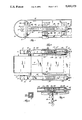
- FIG. 1 is a side elevational view of a belt take-up in accordance with the invention.
- FIG. 2 is a top view showing two belt take-ups, one in fragmentary section.
- FIG. 3 is a sectional view along line 3--3 of FIG. 1.
- FIG. 4 is a diagrammatic view of a modified embodiment.
- FIG. 5 is a cross-section of a modified embodiment of the bearing tube.
- FIG. 6 is an enlarged fragmentary sectional view of the assembly of the spring.
- FIG. 7 is a view similar to FIG. 4 with a different orientation of the load cell.
- a belt 10 is shown which is supported on an idler pulley 12 having a shaft 14 supported in a bearing block 16.
- the belt take-up of the invention includes a bearing support tube 18 which has a mounting plate 20 fixed to the bearing by bolts 22.
- the bearing tube 18 is telescopically received in a slider tube 24 which is supported for recti-linear movement in a third tube outer support tube 28.
- the tube 24 fits into the inside or within the internal cross-section of the tube 28.
- the tube 18 is provided with a side wall having two inclined side wall sections 21, 23 which form a recess 27.
- This recess 27 accommodates and provides clearance for a weld bead or flash 29 which is formed at the joint of the edges of the metal when the tube is formed.
- the recess 27 can be provided with tension indicia 60 as hereinafter described.
- the indicia may be imprinted on an adhesive label and affixed to the surfaces 21, 23 within the outline of the tube so the label will not be scraped away by the outer tube 24 during adjustment of the tension on the bearing support which cause relative movement of the edge 70 of the slider 24 along the gradations or indicia 60.
- the tube 28 is provided with mounting flanges 30 and 32 which are welded to the side of the tube 28 and can be secured by bolts 34 and 36 to the conveyor metal side frame 40.
- the tubes 18, 24 and 28 have a square cross-section as shown in FIG. 3. However, round tubes with keyways or other interfitting geometric cross-section to prevent relative rotation can be utilized.
- adjustment means are provided for adjustably biasing the bearing tube 18 in the direction of arrow 41, FIGS. 1 and 2.
- the adjustment means comprises a threaded rod 50 and a nut 52 having a reduced diameter boss 53 extending therefrom. Reduced boss 53 is placed in hole 57. Then plate 59 is welded to boss 53. The nut is thus loosely fitted into the tube 24. However, the fit of plate 59 in the tube 24 prevents rotation of the nut.
- a square end 54 can be provided on the end of threaded rod for use with a wrench for tightening or loosening the threaded rod 50.
- a nut 56 is threaded on the rod 50 and welded to the rod 50 and located within the end wall 61 of body tube 28.
- the nut 56 bears against tube end wall 61.
- Biasing pressure is afforded by a spring 58 located within the tube 24.
- the spring bears against the lock plate 59 of the floating nut assembly 52 and the end 62 of the bearing support tube 18 to bias the tube 18 in the direction of arrow 41.
- a lock nut is provided on the threaded rod 50 outside the end wall 61.
- a lock plate 59 is welded on the projecting hub 53 on the nut 52.
- the hub 53 projects through an aperture 69 in the end wall 51 of the slider tube 24.
- the aperture 69 is sized to provide a loose fit on the hub 53.
- the lock plate 59, hub 53 and nut 52 thus provide a loose threaded support for the rod 50 to avoid misalignment problems and assure smooth rotational adjustment of the rod 50.
- the spring bears between the end wall 62 and on the lock plate 59 of the floating nut assembly 52. Thus, the bias load goes directly from the spring to the adjuster rod 50.
- the tube 24 simply encloses the spring and serves as a shroud.
- the tube 24 also provides support for bearing tube 18 and functions as a tube container and thread protector.
- the end wall 62 is provided with an aperture 61 for lubrication access.
- a scale 60 can be provided on the bearing tube 18 with the scale readout occurring at the end 70 of the tube 24.
- the scale 60 is desirably numbered on the face 11 as shown in FIG. 1. Then the scale will be in the correct orientation for use on either side of the conveyor.
- a load cell 90 is located between the nut 52 and the end 73 of the spring 58.
- the load cell 90 is electrically connected to a circuit means 79 which can include an electric meter 81 to provide a visual readout of the state of compression of the spring and load cell.
- the load cell 90 can be provided with an aperture 91 (FIGS. 4 and 7).
- the circuit 79 can include a motor controller 82 which can interrupt the circuit to the motor 83 when the belt is at a pre-selected high or low tension value.
- FIG. 7 shows the load cell 90 between the end wall 61 of tube 28 and the nut 56. In this arrangement connection of the circuit wires to the load cell is more convenient.
Landscapes
- Engineering & Computer Science (AREA)
- General Engineering & Computer Science (AREA)
- Mechanical Engineering (AREA)
- Structure Of Belt Conveyors (AREA)
Abstract
A belt take-up for a conveyor is provided with an internal compression spring to adjustably bias the bearing support tube to control tension on the conveyor belt. A scale on the bearing tube can provide a readout of the tension. A load cell can be employed to control a circuit to stop the conveyor motor when extreme high or low tensions of the belt are sensed.
Description
The invention relates to belt take-ups which support bearings for conveyors.
The present invention is a further development of the belt take-ups shown in my U.S. Pat. Nos. 3,832,910 and 4,803,804. These belt take-ups provide unyielding support for the bearings which support the pulley shaft. Some belts are stiff, strong and unyielding so that small incremental adjustment of the belt tension can over stress the belt and do major damage. Moreover, small foreign particles getting between the belt and a driver or idler pulley can untrack or destroy the belt. Additionally, product build-up on the pulley surface adversely affects the belt life and stress. Metal belts, in particular, are affected by heating and cooling which can cause contraction or loosening of the belt by expansion.
A spring loaded belt take-up is provided to overcome these problems. The take-up is provided with a scale for adjusting belts to a predetermined tension. The spring loading also can compensate for the adverse affects of heating and cooling of the belts. The take-up is provided with a visual readout indicating the amount of spring deflection from no load to full load to enable effective tension control on the belt. Rather than utilize a spring, a load cell can be employed with an electric circuit to shut down conveyors if there is too little or too much slack in the belt as sensed by the load cell.
In accordance with the invention, the bearing support tube is telescopically received in an intermediate tube called the slider which contains a spring which bears against the end of the bearing support tube. A floating nut is fixed to the slider tube and a threaded rod causes movement of the nut and the slider tube to compress or release tension on the spring as the threaded rod is rotated. A third outer tube, called the body, supports the threaded rod adjuster for rotation and telescopically receives the bearing support and slider tubes. The indicia for readout on spring tension is provided on the exposed end of the bearing support tube. The end of the slider tube can be used as the pointer or bench mark for reading the scale.
Further objects, advantages and features of the invention will become apparent from the disclosure.
FIG. 1 is a side elevational view of a belt take-up in accordance with the invention.
FIG. 2 is a top view showing two belt take-ups, one in fragmentary section.
FIG. 3 is a sectional view along line 3--3 of FIG. 1.
FIG. 4 is a diagrammatic view of a modified embodiment.
FIG. 5 is a cross-section of a modified embodiment of the bearing tube.
FIG. 6 is an enlarged fragmentary sectional view of the assembly of the spring.
FIG. 7 is a view similar to FIG. 4 with a different orientation of the load cell.
Although the disclosure hereof is detailed and exact to enable those skilled in the art to practice the invention, the physical embodiments herein disclosed merely exemplify the invention which may be embodied in other specific structure. The scope of the invention is defined in the claims appended hereto.
In the drawings a belt 10 is shown which is supported on an idler pulley 12 having a shaft 14 supported in a bearing block 16.
The belt take-up of the invention includes a bearing support tube 18 which has a mounting plate 20 fixed to the bearing by bolts 22. The bearing tube 18 is telescopically received in a slider tube 24 which is supported for recti-linear movement in a third tube outer support tube 28. The tube 24 fits into the inside or within the internal cross-section of the tube 28. In a modified embodiment the tube 18 is provided with a side wall having two inclined side wall sections 21, 23 which form a recess 27. This recess 27 accommodates and provides clearance for a weld bead or flash 29 which is formed at the joint of the edges of the metal when the tube is formed. The recess 27 can be provided with tension indicia 60 as hereinafter described. The indicia may be imprinted on an adhesive label and affixed to the surfaces 21, 23 within the outline of the tube so the label will not be scraped away by the outer tube 24 during adjustment of the tension on the bearing support which cause relative movement of the edge 70 of the slider 24 along the gradations or indicia 60. The tube 28 is provided with mounting flanges 30 and 32 which are welded to the side of the tube 28 and can be secured by bolts 34 and 36 to the conveyor metal side frame 40. In the disclosed construction, the tubes 18, 24 and 28 have a square cross-section as shown in FIG. 3. However, round tubes with keyways or other interfitting geometric cross-section to prevent relative rotation can be utilized.
In accordance with the invention, adjustment means are provided for adjustably biasing the bearing tube 18 in the direction of arrow 41, FIGS. 1 and 2. In the disclosed construction, the adjustment means comprises a threaded rod 50 and a nut 52 having a reduced diameter boss 53 extending therefrom. Reduced boss 53 is placed in hole 57. Then plate 59 is welded to boss 53. The nut is thus loosely fitted into the tube 24. However, the fit of plate 59 in the tube 24 prevents rotation of the nut. A square end 54 can be provided on the end of threaded rod for use with a wrench for tightening or loosening the threaded rod 50.
A nut 56 is threaded on the rod 50 and welded to the rod 50 and located within the end wall 61 of body tube 28. The nut 56 bears against tube end wall 61. Biasing pressure is afforded by a spring 58 located within the tube 24. The spring bears against the lock plate 59 of the floating nut assembly 52 and the end 62 of the bearing support tube 18 to bias the tube 18 in the direction of arrow 41. A lock nut is provided on the threaded rod 50 outside the end wall 61. A lock plate 59 is welded on the projecting hub 53 on the nut 52. The hub 53 projects through an aperture 69 in the end wall 51 of the slider tube 24. The aperture 69 is sized to provide a loose fit on the hub 53. The lock plate 59, hub 53 and nut 52 thus provide a loose threaded support for the rod 50 to avoid misalignment problems and assure smooth rotational adjustment of the rod 50. The spring bears between the end wall 62 and on the lock plate 59 of the floating nut assembly 52. Thus, the bias load goes directly from the spring to the adjuster rod 50. The tube 24 simply encloses the spring and serves as a shroud. The tube 24 also provides support for bearing tube 18 and functions as a tube container and thread protector. In this regard the end wall 62 is provided with an aperture 61 for lubrication access.
A scale 60 can be provided on the bearing tube 18 with the scale readout occurring at the end 70 of the tube 24. The scale 60 is desirably numbered on the face 11 as shown in FIG. 1. Then the scale will be in the correct orientation for use on either side of the conveyor.
In use of the belt tensioner rotational movement of the screw 50 by applying torque to the end 54 will cause movement of the tube 24 to compress or release tension on the spring. The corresponding force is applied to the end 62 of the tube as shown in FIG. 2.
In an alternate construction as shown in FIG. 4, a load cell 90 is located between the nut 52 and the end 73 of the spring 58. The load cell 90 is electrically connected to a circuit means 79 which can include an electric meter 81 to provide a visual readout of the state of compression of the spring and load cell. The load cell 90 can be provided with an aperture 91 (FIGS. 4 and 7). The circuit 79 can include a motor controller 82 which can interrupt the circuit to the motor 83 when the belt is at a pre-selected high or low tension value. FIG. 7 shows the load cell 90 between the end wall 61 of tube 28 and the nut 56. In this arrangement connection of the circuit wires to the load cell is more convenient.
Claims (11)
1. A belt take-up including a bearing support tube, a slider tube and a body tube, said bearing support tube interfitting in said slider tube to provide relative longitudinal movement but not rotational movement, said bearing support tube having an end and being telescopically and reciprocally received in said slider tube with said bearing support tube and said slider tube being supported in said body and including means for adjustably biasing the bearing support tube and wherein said means for adjustably biasing said bearing support tube comprises a threaded rod having a free end, means for rotatably supporting the threaded rod in said body tube and for limiting axial movement of said rod, a nut threadably received on said rod and secured to said slider tube and a spring between said nut and said bearing support tube and telescoped over said threaded rod and said spring engaging said bearing support tube end which is spaced from the end of said bearing support tube to provide clearance for adjustment of said threaded rod to afford the bearing tube to float against the spring bias in a recti-linear path during tension on the belt so that rotation of said threaded rod causes movement of said nut and said slider tube to compress or reduce the compression of said spring and thereby vary the compression on said bearing support tube.
2. The belt take-up of claim 1 wherein said means for adjustably biasing said bearing support tube comprises a threaded rod, means for rotatably supporting the threaded rod in said body tube and for limiting axial movement of said rod, and nut threadably received on said rod and secured to said slider tube and a spring between said nut and said bearing support tube so that rotation of said threaded rod causes movement of said nut and said slider tube to compress or reduce the compression of said spring and thereby vary the compression on said bearing support tube and its bearing.
3. The belt take-up of claim 1 wherein said means for adjustably biasing said bearing support tube includes a load cell and circuit means connected to said load cell to provide a visual readout of the state of said load cell,
means for supporting said load cell within said body tube in a position to react to the compressive forces on said bearing support tube.
4. A belt take-up in accordance with claim 3 wherein said load cell has a central aperture and is located within said slider tube said slider tube having a threaded end member and said load cell being located between said end member of said slider tube and the end of said bearing tube and being arranged around said threaded rod.
5. A belt take-up in accordance with claim 3 wherein said load cell is located within said slider tube and between an end of said spring and the nut assembly.
6. A belt take-up in accordance with claim 1 wherein said bearing support tube has a scale with indicia for readout of the compressive force on said bearing support tube when under load.
7. A belt take-up including a bearing support tube, a slider tube and an outer body tube, said bearing support tube interfitting in said slider tube to provide relative longitudinal movement but not rotational movement, said bearing support tube being telescopically and reciprocally received in said slider tube with said bearing support tube and said slider tube being supported in said outer tube and including means within said body tube for adjustably biasing the bearing support tube to provide a predetermined compressive load on said belt take-up.
8. The belt take-up of claim 7 wherein said means for adjustably biasing said bearing support tube comprises a threaded rod, means for rotatably supporting the threaded rod in said body tube and for limiting axial movement of said rod, a nut threadably received on said rod and secured to said slider tube and a spring between said nut and said bearing support tube so that rotation of said threaded rod causes movement of said nut and said slider tube to compress or reduce the compression of said spring and thereby vary the tension on said bearing support tube and enable the bearing tube to float back and forth in response to changes in belt tension.
9. The belt take-up of claim 3 including a second belt take-up both of said belt take-ups in combination with a motor driven conveyor having bearing blocks connected to said belt take-up bearing support tubes, a shaft with a pulley rotatably supported in said bearing blocks, a conveyor frame for supporting the belt take-ups and a conveyor belt arranged around said pulley whereby said means for adjustably biasing the bearing support tubes in said belt take-ups affords belt tension adjustment and circuit means connecting said load cell to a switch to change the state of equipment associated with the conveyor assembly if the tension in the belt attains a pre-selected level.
10. The combination of claim 9 including indicia on said bearing support tubes to measure the tension on said belt.
11. A belt take-up according to claim 7 wherein said slider tube has an end which telescopes over an exposed portion of said bearing support tube during adjustment of said biasing means and a scale on said exposed portion which cooperates with said slider tube end to provide a visual read out of the bearing force on said bearing tube.
Priority Applications (1)
| Application Number | Priority Date | Filing Date | Title |
|---|---|---|---|
| US07/500,379 US5030173A (en) | 1990-03-28 | 1990-03-28 | Spring loaded telescopic tube take-up |
Applications Claiming Priority (1)
| Application Number | Priority Date | Filing Date | Title |
|---|---|---|---|
| US07/500,379 US5030173A (en) | 1990-03-28 | 1990-03-28 | Spring loaded telescopic tube take-up |
Publications (1)
| Publication Number | Publication Date |
|---|---|
| US5030173A true US5030173A (en) | 1991-07-09 |
Family
ID=23989156
Family Applications (1)
| Application Number | Title | Priority Date | Filing Date |
|---|---|---|---|
| US07/500,379 Expired - Lifetime US5030173A (en) | 1990-03-28 | 1990-03-28 | Spring loaded telescopic tube take-up |
Country Status (1)
| Country | Link |
|---|---|
| US (1) | US5030173A (en) |
Cited By (52)
| Publication number | Priority date | Publication date | Assignee | Title |
|---|---|---|---|---|
| EP0497045A1 (en) * | 1991-01-30 | 1992-08-05 | Teleflex Incorporated | Modular cargo drive unit for a conveyor |
| US5183441A (en) * | 1992-02-03 | 1993-02-02 | Ingersoll-Rand Company | Belt sander tensioner |
| US5259821A (en) * | 1991-12-27 | 1993-11-09 | Bryant Products, Inc. | Linear spacing device |
| US5302162A (en) * | 1992-11-05 | 1994-04-12 | Precor Incorporated | Exercise treadmill with tension-limited belt adjustment |
| US5546665A (en) * | 1994-03-17 | 1996-08-20 | Jackmauh; John A. | Motorcycle rear wheel alignment system |
| US5772549A (en) * | 1995-12-12 | 1998-06-30 | Muhr Und Bender | Belt tensioning device |
| US6030305A (en) * | 1998-09-28 | 2000-02-29 | Ingersoll-Rand Company | Semi-automatic tensioner for a belt drive system |
| US6200036B1 (en) * | 1999-09-28 | 2001-03-13 | Reliance Electric Technologies, Llc | Take-up frame system and method with force feedback |
| US20030109343A1 (en) * | 2001-12-11 | 2003-06-12 | Lee Martinson | Drive belt stabilizer system |
| US6679149B2 (en) * | 1999-07-06 | 2004-01-20 | Premark Feg L.L.C. | Band saw apparatus with blade tensioner and related method |
| US20050014588A1 (en) * | 2003-07-18 | 2005-01-20 | Gebrian Peter Louis | Bi-directional drivebelt tensioning device |
| US20050037878A1 (en) * | 2003-08-14 | 2005-02-17 | York International Corporation | Motor belt tensioning construction for an air handling unit |
| US20050178215A1 (en) * | 2004-02-18 | 2005-08-18 | Edward Mayer | Linkage and sensor assembly |
| US20060183585A1 (en) * | 2005-02-11 | 2006-08-17 | Quantum Corporation | Integrated belt tensioning devices and associated methods |
| US7181845B2 (en) | 2003-02-28 | 2007-02-27 | Bryant Products, Inc. | Roller with integral bearing assembly mount and method for manufacturing same |
| US20080044117A1 (en) * | 2006-08-21 | 2008-02-21 | Reliance Electric Technologies, Llc | Load indicating take-up frame |
| US20080113836A1 (en) * | 2006-11-14 | 2008-05-15 | General Electric Company, A New York Corporation | Automatic tensioning mount for belts |
| US20090062046A1 (en) * | 2007-09-04 | 2009-03-05 | Robert Lindemann | Belt tensioner with adjustable slider plate and replaceable pulley |
| US20090188331A1 (en) * | 2008-01-24 | 2009-07-30 | Ebm Mill & Elevator Supply Inc. | Belt conveying tension measuring system |
| US20090255348A1 (en) * | 2008-01-24 | 2009-10-15 | Ebm Properties Inc. | Belt conveying tension measuring system |
| DE102008024314A1 (en) | 2008-05-20 | 2009-11-26 | Bizerba Gmbh & Co Kg | Conveyor belt has belt body, at which two guide rollers are held, and endless belt is guided through guide rollers, where guide rollers have fine adjustment with adjusting screw |
| US7673738B2 (en) | 2003-05-02 | 2010-03-09 | Ancra International Llc | Steerable/retractable cargo power drive unit |
| ITCR20080019A1 (en) * | 2008-10-02 | 2010-04-03 | Protec Srl | SLIDING SUPPORT FOR BEARINGS |
| CN103015302A (en) * | 2012-12-21 | 2013-04-03 | 中联重科股份有限公司 | Belt tensioning device and pavement milling equipment |
| US20130095968A1 (en) * | 2011-10-14 | 2013-04-18 | D B Industries, Inc. | Cable drive and tension assembly |
| CN103508163A (en) * | 2013-01-22 | 2014-01-15 | 山西长治维特衡器有限公司 | Belt tensioning device |
| WO2014029011A1 (en) * | 2012-08-23 | 2014-02-27 | Woodhaven Capital Corp. | Belt conveyor |
| EP2957164A1 (en) * | 2014-06-18 | 2015-12-23 | Deere & Company | Inclined conveyor assembly for a combine harvester |
| USD750864S1 (en) | 2013-09-06 | 2016-03-01 | Bryant Products Inc. | Conveyor belt tightener |
| CN105366286A (en) * | 2015-09-30 | 2016-03-02 | 湖南晟通天力汽车有限公司 | Automobile, belt-type transmission system thereof and tension adjusting device |
| US9371189B1 (en) | 2013-10-16 | 2016-06-21 | Bryant Products, Inc. | Telescoping belt tightener with integrated bearing housing |
| US20160230851A1 (en) * | 2015-02-06 | 2016-08-11 | FLIR Belgium BVBA | Belt drive tensioning system |
| US20170114639A1 (en) * | 2015-05-08 | 2017-04-27 | Joy Mm Delaware, Inc. | Controlling a conveyor in a mining system |
| US9643786B1 (en) | 2016-05-20 | 2017-05-09 | Bryant Products, Inc. | Food-grade telescoping belt tightener |
| WO2017181188A1 (en) * | 2016-04-15 | 2017-10-19 | Joy Mm Delaware, Inc. | Systems and methods for tensioning a conveyor in a mining system |
| CN107269784A (en) * | 2017-08-04 | 2017-10-20 | 陕西中烟工业有限责任公司 | A kind of V-belt pre-tightening apparatus and its application method |
| US10071862B1 (en) | 2017-03-10 | 2018-09-11 | Flexicon Corporation | Automated tensioning system for cable or chain conveyor |
| US20180319602A1 (en) * | 2017-05-03 | 2018-11-08 | Dematic Corp. | Conveyor belt drive system and configuration |
| US20180332772A1 (en) * | 2017-05-22 | 2018-11-22 | Claas Selbstfahrende Erntemaschinen Gmbh | Header |
| US10149437B2 (en) * | 2016-03-01 | 2018-12-11 | Cnh Industrial America Llc | Feeder conveyor assembly tensioning mechanism |
| US20190256295A1 (en) * | 2018-02-21 | 2019-08-22 | Dyco, Inc. | Cable tensioner |
| US20190380273A1 (en) * | 2018-06-18 | 2019-12-19 | Deere & Company | Draper belt tensioner with worm and sector gear |
| US20200000038A1 (en) * | 2018-07-02 | 2020-01-02 | Cnh Industrial America Llc | System for adjusting the conveyor belt tension force within an agricultural harvester |
| US10569960B2 (en) | 2018-07-19 | 2020-02-25 | Joy Global Underground Mining Llc | System and method for tensioning a conveyor in a mining system |
| RU205735U1 (en) * | 2021-02-03 | 2021-08-03 | Денис Сергеевич Новиков | ENGINE CHAIN TENSIONER |
| RU206175U1 (en) * | 2021-02-03 | 2021-08-26 | Денис Сергеевич Новиков | ENGINE CHAIN TENSIONER |
| US11273990B2 (en) * | 2019-11-18 | 2022-03-15 | Cnh Industrial America Llc | Draper belt tensioning system |
| US20220154806A1 (en) * | 2019-02-25 | 2022-05-19 | Borgwarner Sweden Ab | Chain tensioning of a hybrid drive module |
| US11536350B1 (en) * | 2021-06-28 | 2022-12-27 | Lennox Industries Inc. | Tensioning systems and methods |
| CN117566377A (en) * | 2024-01-17 | 2024-02-20 | 山东中博重工机械有限公司 | Belt conveyor with adjustable conveying path |
| CN117922908A (en) * | 2023-12-22 | 2024-04-26 | 新疆天鹅现代农业机械装备有限公司 | Horizontal cotton conveying belt of cotton picker with sliding rail type adjustable tensioning force |
| US20240147905A1 (en) * | 2022-11-03 | 2024-05-09 | Kuhn Sas | Belt tensioning system |
Citations (7)
| Publication number | Priority date | Publication date | Assignee | Title |
|---|---|---|---|---|
| US2407499A (en) * | 1946-09-10 | Measured tension control for | ||
| US3422692A (en) * | 1967-05-10 | 1969-01-21 | Int Harvester Co | Belt tightener with stretch indicating means |
| US3520182A (en) * | 1967-06-05 | 1970-07-14 | Kelk Ltd George | Load cells |
| US3832910A (en) * | 1972-06-15 | 1974-09-03 | C Bryant | Telescopic belt tightener |
| US4583961A (en) * | 1983-06-23 | 1986-04-22 | Toyota Jidosha Kabushiki Kaisha | Belt tensioner |
| US4803804A (en) * | 1987-09-14 | 1989-02-14 | Bryant Charles B | Telescopic belt tightener |
| US4820283A (en) * | 1988-01-13 | 1989-04-11 | Baxter Travenol Laboratories, Inc. | Shear force gauge |
-
1990
- 1990-03-28 US US07/500,379 patent/US5030173A/en not_active Expired - Lifetime
Patent Citations (7)
| Publication number | Priority date | Publication date | Assignee | Title |
|---|---|---|---|---|
| US2407499A (en) * | 1946-09-10 | Measured tension control for | ||
| US3422692A (en) * | 1967-05-10 | 1969-01-21 | Int Harvester Co | Belt tightener with stretch indicating means |
| US3520182A (en) * | 1967-06-05 | 1970-07-14 | Kelk Ltd George | Load cells |
| US3832910A (en) * | 1972-06-15 | 1974-09-03 | C Bryant | Telescopic belt tightener |
| US4583961A (en) * | 1983-06-23 | 1986-04-22 | Toyota Jidosha Kabushiki Kaisha | Belt tensioner |
| US4803804A (en) * | 1987-09-14 | 1989-02-14 | Bryant Charles B | Telescopic belt tightener |
| US4820283A (en) * | 1988-01-13 | 1989-04-11 | Baxter Travenol Laboratories, Inc. | Shear force gauge |
Cited By (92)
| Publication number | Priority date | Publication date | Assignee | Title |
|---|---|---|---|---|
| EP0497045A1 (en) * | 1991-01-30 | 1992-08-05 | Teleflex Incorporated | Modular cargo drive unit for a conveyor |
| US5259821A (en) * | 1991-12-27 | 1993-11-09 | Bryant Products, Inc. | Linear spacing device |
| US5183441A (en) * | 1992-02-03 | 1993-02-02 | Ingersoll-Rand Company | Belt sander tensioner |
| US5302162A (en) * | 1992-11-05 | 1994-04-12 | Precor Incorporated | Exercise treadmill with tension-limited belt adjustment |
| US5546665A (en) * | 1994-03-17 | 1996-08-20 | Jackmauh; John A. | Motorcycle rear wheel alignment system |
| US5772549A (en) * | 1995-12-12 | 1998-06-30 | Muhr Und Bender | Belt tensioning device |
| US6030305A (en) * | 1998-09-28 | 2000-02-29 | Ingersoll-Rand Company | Semi-automatic tensioner for a belt drive system |
| US6679149B2 (en) * | 1999-07-06 | 2004-01-20 | Premark Feg L.L.C. | Band saw apparatus with blade tensioner and related method |
| US6200036B1 (en) * | 1999-09-28 | 2001-03-13 | Reliance Electric Technologies, Llc | Take-up frame system and method with force feedback |
| US20030109343A1 (en) * | 2001-12-11 | 2003-06-12 | Lee Martinson | Drive belt stabilizer system |
| US20040097312A1 (en) * | 2001-12-11 | 2004-05-20 | Lee Martinson | Drive belt stabilizer system |
| US7181845B2 (en) | 2003-02-28 | 2007-02-27 | Bryant Products, Inc. | Roller with integral bearing assembly mount and method for manufacturing same |
| US7673738B2 (en) | 2003-05-02 | 2010-03-09 | Ancra International Llc | Steerable/retractable cargo power drive unit |
| US20050014588A1 (en) * | 2003-07-18 | 2005-01-20 | Gebrian Peter Louis | Bi-directional drivebelt tensioning device |
| US7207913B2 (en) | 2003-07-18 | 2007-04-24 | Dade Behring Inc. | Bi-directional drivebelt tensioning device |
| US20050037878A1 (en) * | 2003-08-14 | 2005-02-17 | York International Corporation | Motor belt tensioning construction for an air handling unit |
| US7338400B2 (en) | 2003-08-14 | 2008-03-04 | Johnson Controls Technology Company | Motor belt tensioning construction for an air handling unit |
| US7296487B2 (en) * | 2004-02-18 | 2007-11-20 | Curtiss Wright Controls, Inc. | Linkage and sensor assembly |
| US20070277625A1 (en) * | 2004-02-18 | 2007-12-06 | Curtiss Wright Controls, Inc. | Linkage and sensor assembly |
| US20050178215A1 (en) * | 2004-02-18 | 2005-08-18 | Edward Mayer | Linkage and sensor assembly |
| US7430927B2 (en) * | 2004-02-18 | 2008-10-07 | Curtiss Wright Controls, Inc. | Linkage and sensor assembly |
| EP1691109A3 (en) * | 2005-02-11 | 2006-11-22 | Quantum Corporation | Integrated belt tensioning devices and associated methods |
| US20060183585A1 (en) * | 2005-02-11 | 2006-08-17 | Quantum Corporation | Integrated belt tensioning devices and associated methods |
| US20080044117A1 (en) * | 2006-08-21 | 2008-02-21 | Reliance Electric Technologies, Llc | Load indicating take-up frame |
| US7493825B2 (en) * | 2006-08-21 | 2009-02-24 | Reliance Electric Technologies, Llc | Load indicating take-up frame |
| US20080113836A1 (en) * | 2006-11-14 | 2008-05-15 | General Electric Company, A New York Corporation | Automatic tensioning mount for belts |
| US8128074B2 (en) * | 2006-11-14 | 2012-03-06 | General Electric Company | Automatic tensioning mount for belts |
| US20090062046A1 (en) * | 2007-09-04 | 2009-03-05 | Robert Lindemann | Belt tensioner with adjustable slider plate and replaceable pulley |
| US20090188331A1 (en) * | 2008-01-24 | 2009-07-30 | Ebm Mill & Elevator Supply Inc. | Belt conveying tension measuring system |
| US20090255348A1 (en) * | 2008-01-24 | 2009-10-15 | Ebm Properties Inc. | Belt conveying tension measuring system |
| US7806004B2 (en) | 2008-01-24 | 2010-10-05 | Ebm Properties Inc. | Belt conveying tension measuring system |
| US8024983B2 (en) | 2008-01-24 | 2011-09-27 | Ebm Properties Inc. | Belt conveying tension measuring system |
| DE102008024314A1 (en) | 2008-05-20 | 2009-11-26 | Bizerba Gmbh & Co Kg | Conveyor belt has belt body, at which two guide rollers are held, and endless belt is guided through guide rollers, where guide rollers have fine adjustment with adjusting screw |
| DE102008024314B4 (en) * | 2008-05-20 | 2017-05-18 | Bizerba SE & Co. KG | conveyor belt |
| ITCR20080019A1 (en) * | 2008-10-02 | 2010-04-03 | Protec Srl | SLIDING SUPPORT FOR BEARINGS |
| US20130095968A1 (en) * | 2011-10-14 | 2013-04-18 | D B Industries, Inc. | Cable drive and tension assembly |
| US8974334B2 (en) * | 2011-10-14 | 2015-03-10 | D B Industries, Llc | Cable drive and tension assembly |
| US8770390B2 (en) | 2012-08-23 | 2014-07-08 | Woodhaven Capital Corp. | Belt conveyor |
| WO2014029011A1 (en) * | 2012-08-23 | 2014-02-27 | Woodhaven Capital Corp. | Belt conveyor |
| CN103015302B (en) * | 2012-12-21 | 2015-09-16 | 中联重科股份有限公司 | Belt tensioning device and pavement milling equipment |
| CN103015302A (en) * | 2012-12-21 | 2013-04-03 | 中联重科股份有限公司 | Belt tensioning device and pavement milling equipment |
| CN103508163A (en) * | 2013-01-22 | 2014-01-15 | 山西长治维特衡器有限公司 | Belt tensioning device |
| USD750864S1 (en) | 2013-09-06 | 2016-03-01 | Bryant Products Inc. | Conveyor belt tightener |
| US9371189B1 (en) | 2013-10-16 | 2016-06-21 | Bryant Products, Inc. | Telescoping belt tightener with integrated bearing housing |
| US9485915B2 (en) * | 2014-06-18 | 2016-11-08 | Deere & Company | Combine harvester having a feederhouse |
| US20150366139A1 (en) * | 2014-06-18 | 2015-12-24 | Deere & Company | Combine Harvester Having a Feederhouse |
| EP2957164A1 (en) * | 2014-06-18 | 2015-12-23 | Deere & Company | Inclined conveyor assembly for a combine harvester |
| US20160230851A1 (en) * | 2015-02-06 | 2016-08-11 | FLIR Belgium BVBA | Belt drive tensioning system |
| US10156290B2 (en) * | 2015-02-06 | 2018-12-18 | FLIR Belgium BVBA | Belt drive tensioning system |
| US9809393B2 (en) | 2015-05-08 | 2017-11-07 | Joy Mm Delaware, Inc. | Controlling a conveyor in a mining system |
| US20170114639A1 (en) * | 2015-05-08 | 2017-04-27 | Joy Mm Delaware, Inc. | Controlling a conveyor in a mining system |
| US9776803B2 (en) * | 2015-05-08 | 2017-10-03 | Joy Mm Delaware, Inc. | Controlling a conveyor in a mining system |
| CN105366286A (en) * | 2015-09-30 | 2016-03-02 | 湖南晟通天力汽车有限公司 | Automobile, belt-type transmission system thereof and tension adjusting device |
| CN105366286B (en) * | 2015-09-30 | 2017-09-26 | 湖南晟通天力汽车有限公司 | Automobile and its belt Transmission system and tensile force adjusting device |
| US10149437B2 (en) * | 2016-03-01 | 2018-12-11 | Cnh Industrial America Llc | Feeder conveyor assembly tensioning mechanism |
| US10486911B2 (en) | 2016-04-15 | 2019-11-26 | Joy Global Underground Mining Llc | Systems and methods for tensioning a conveyor in a mining system |
| US9932177B2 (en) | 2016-04-15 | 2018-04-03 | Joy Mm Delaware, Inc. | Systems and methods for tensioning a conveyor in a mining system |
| US10793366B2 (en) | 2016-04-15 | 2020-10-06 | Joy Global Underground Mining Llc | Systems and methods for tensioning a conveyor in a mining system |
| AU2017250380B2 (en) * | 2016-04-15 | 2022-06-16 | Joy Global Underground Mining Llc | Systems and methods for tensioning a conveyor in a mining system |
| CN111661569A (en) * | 2016-04-15 | 2020-09-15 | 久益环球地下采矿有限责任公司 | System and method for tensioning a conveyor in a mining system |
| CN109311596A (en) * | 2016-04-15 | 2019-02-05 | 久益环球地下采矿有限责任公司 | System and method for tensioning a conveyor in a mining system |
| CN109311596B (en) * | 2016-04-15 | 2020-07-07 | 久益环球地下采矿有限责任公司 | System and method for tensioning a conveyor in a mining system |
| WO2017181188A1 (en) * | 2016-04-15 | 2017-10-19 | Joy Mm Delaware, Inc. | Systems and methods for tensioning a conveyor in a mining system |
| US9643786B1 (en) | 2016-05-20 | 2017-05-09 | Bryant Products, Inc. | Food-grade telescoping belt tightener |
| NO344672B1 (en) * | 2017-03-10 | 2020-03-02 | Flexicon Corp | Automated tensioning system for cable or chain conveyor |
| AU2018230405B9 (en) * | 2017-03-10 | 2020-03-26 | Flexicon Corporation | Automated tensioning system for cable or chain conveyor |
| AU2018230405B2 (en) * | 2017-03-10 | 2020-03-05 | Flexicon Corporation | Automated tensioning system for cable or chain conveyor |
| WO2018165436A1 (en) | 2017-03-10 | 2018-09-13 | Flexicon Corporation | Automated tensioning system for cable or chain conveyor |
| US10071862B1 (en) | 2017-03-10 | 2018-09-11 | Flexicon Corporation | Automated tensioning system for cable or chain conveyor |
| US10384879B2 (en) * | 2017-05-03 | 2019-08-20 | Dematic Corp. | Conveyor belt drive system and configuration |
| US20180319602A1 (en) * | 2017-05-03 | 2018-11-08 | Dematic Corp. | Conveyor belt drive system and configuration |
| US20180332772A1 (en) * | 2017-05-22 | 2018-11-22 | Claas Selbstfahrende Erntemaschinen Gmbh | Header |
| US10575467B2 (en) * | 2017-05-22 | 2020-03-03 | Claas Selbstfahrende Erntemaschinen Gmbh | Agricultural header |
| CN107269784A (en) * | 2017-08-04 | 2017-10-20 | 陕西中烟工业有限责任公司 | A kind of V-belt pre-tightening apparatus and its application method |
| US20190256295A1 (en) * | 2018-02-21 | 2019-08-22 | Dyco, Inc. | Cable tensioner |
| US10421614B2 (en) * | 2018-02-21 | 2019-09-24 | Dyco, Inc. | Cable tensioner |
| US10660272B2 (en) * | 2018-06-18 | 2020-05-26 | Deere & Company | Draper belt tensioner with worm and sector gear |
| US20190380273A1 (en) * | 2018-06-18 | 2019-12-19 | Deere & Company | Draper belt tensioner with worm and sector gear |
| US20200000038A1 (en) * | 2018-07-02 | 2020-01-02 | Cnh Industrial America Llc | System for adjusting the conveyor belt tension force within an agricultural harvester |
| US10918019B2 (en) * | 2018-07-02 | 2021-02-16 | Cnh Industrial America Llc | System for adjusting the conveyor belt tension force within an agricultural harvester |
| US10569960B2 (en) | 2018-07-19 | 2020-02-25 | Joy Global Underground Mining Llc | System and method for tensioning a conveyor in a mining system |
| US20220154806A1 (en) * | 2019-02-25 | 2022-05-19 | Borgwarner Sweden Ab | Chain tensioning of a hybrid drive module |
| US11273990B2 (en) * | 2019-11-18 | 2022-03-15 | Cnh Industrial America Llc | Draper belt tensioning system |
| RU206175U1 (en) * | 2021-02-03 | 2021-08-26 | Денис Сергеевич Новиков | ENGINE CHAIN TENSIONER |
| RU205735U1 (en) * | 2021-02-03 | 2021-08-03 | Денис Сергеевич Новиков | ENGINE CHAIN TENSIONER |
| US11536350B1 (en) * | 2021-06-28 | 2022-12-27 | Lennox Industries Inc. | Tensioning systems and methods |
| US20220412438A1 (en) * | 2021-06-28 | 2022-12-29 | Lennox Industries Inc. | Tensioning systems and methods |
| US11859720B2 (en) | 2021-06-28 | 2024-01-02 | Lennox Industries Inc. | Tensioning systems and methods |
| US20240147905A1 (en) * | 2022-11-03 | 2024-05-09 | Kuhn Sas | Belt tensioning system |
| CN117922908A (en) * | 2023-12-22 | 2024-04-26 | 新疆天鹅现代农业机械装备有限公司 | Horizontal cotton conveying belt of cotton picker with sliding rail type adjustable tensioning force |
| CN117566377A (en) * | 2024-01-17 | 2024-02-20 | 山东中博重工机械有限公司 | Belt conveyor with adjustable conveying path |
| CN117566377B (en) * | 2024-01-17 | 2024-03-29 | 山东中博重工机械有限公司 | Belt conveyor with adjustable conveying path |
Similar Documents
| Publication | Publication Date | Title |
|---|---|---|
| US5030173A (en) | Spring loaded telescopic tube take-up | |
| US6131302A (en) | Device for measuring the extension of a threaded bolt or screw | |
| US5584627A (en) | Load indicating fasteners | |
| US4767383A (en) | Adjustable tensioner for belt and chain drives | |
| US4170826A (en) | Longitudinal measuring device with longitudinally displaceable scale | |
| US5005424A (en) | Machine and method for uniaxial mechanical material testing | |
| US4573952A (en) | Tensioning device with a control mechanism for the tension of a belt | |
| CN1094589C (en) | Method and device for marking loads | |
| US3955636A (en) | Weighing apparatus for truck and vehicle loads | |
| US4198921A (en) | Fluid pressure actuators indicator | |
| US4185504A (en) | Apparatus for measuring the pre-tension of a threaded bolt | |
| US6003657A (en) | Self-indicating tensioner for a belt scraper | |
| US3867990A (en) | Weighing apparatus for truck and vehicle loads | |
| US6892585B2 (en) | Variable amplification bolt load indicator apparatus and a method of making and using the apparatus | |
| US11971086B2 (en) | Cable tensioner | |
| WO2001020286A1 (en) | Web tension transducer apparatus | |
| US3382710A (en) | Torque-measuring devices | |
| US2706903A (en) | Torque measuring device | |
| SU993062A1 (en) | Method of checking threaded joint tightening force | |
| KR200216726Y1 (en) | Chain tensioner | |
| US4653318A (en) | Electronic stator measurement device | |
| SU916791A1 (en) | Fastening bolt indicating device | |
| KR100260642B1 (en) | Adjust bolt for setting the tension of drive belt | |
| JPS59209772A (en) | Detector for clamping force of screw | |
| JPS60152927A (en) | Axial-tension controlling method of clamping bolt and clamping bolt used in this method |
Legal Events
| Date | Code | Title | Description |
|---|---|---|---|
| STCF | Information on status: patent grant |
Free format text: PATENTED CASE |
|
| AS | Assignment |
Owner name: BRYANT PRODUCTS, INC., WISCONSIN Free format text: ASSIGNMENT OF ASSIGNORS INTEREST.;ASSIGNOR:BRYANT, CHARLES B.;REEL/FRAME:006497/0045 Effective date: 19930330 |
|
| FEPP | Fee payment procedure |
Free format text: PAYOR NUMBER ASSIGNED (ORIGINAL EVENT CODE: ASPN); ENTITY STATUS OF PATENT OWNER: SMALL ENTITY |
|
| FPAY | Fee payment |
Year of fee payment: 4 |
|
| FPAY | Fee payment |
Year of fee payment: 8 |
|
| FPAY | Fee payment |
Year of fee payment: 12 |