US502A - Through trees - Google Patents
Through trees Download PDFInfo
- Publication number
- US502A US502A US502DA US502A US 502 A US502 A US 502A US 502D A US502D A US 502DA US 502 A US502 A US 502A
- Authority
- US
- United States
- Prior art keywords
- saw
- machine
- slide
- parts
- arm
- Prior art date
- Legal status (The legal status is an assumption and is not a legal conclusion. Google has not performed a legal analysis and makes no representation as to the accuracy of the status listed.)
- Expired - Lifetime
Links
Images

Classifications
-
- B—PERFORMING OPERATIONS; TRANSPORTING
- B27—WORKING OR PRESERVING WOOD OR SIMILAR MATERIAL; NAILING OR STAPLING MACHINES IN GENERAL
- B27B—SAWS FOR WOOD OR SIMILAR MATERIAL; COMPONENTS OR ACCESSORIES THEREFOR
- B27B11/00—Cross-cut reciprocating saws with power drive; Appurtenances therefor
-
- Y—GENERAL TAGGING OF NEW TECHNOLOGICAL DEVELOPMENTS; GENERAL TAGGING OF CROSS-SECTIONAL TECHNOLOGIES SPANNING OVER SEVERAL SECTIONS OF THE IPC; TECHNICAL SUBJECTS COVERED BY FORMER USPC CROSS-REFERENCE ART COLLECTIONS [XRACs] AND DIGESTS
- Y10—TECHNICAL SUBJECTS COVERED BY FORMER USPC
- Y10T—TECHNICAL SUBJECTS COVERED BY FORMER US CLASSIFICATION
- Y10T83/00—Cutting
- Y10T83/687—By tool reciprocable along elongated edge
- Y10T83/6905—With tool in-feed
- Y10T83/693—Of rectilinearly reciprocating tool
- Y10T83/6935—With in-feed by pivoting carrier
Landscapes
- Life Sciences & Earth Sciences (AREA)
- Engineering & Computer Science (AREA)
- Mechanical Engineering (AREA)
- Wood Science & Technology (AREA)
- Forests & Forestry (AREA)
- Sawing (AREA)
Description
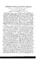
AM PHOTO-LITHO. C0. NYY EEEEEEEEEEEEEEE S) ITED STATES PATENT onirica.
SAMUEL H. HAMILTON, =OF NEW YORK, N, Y.
lIVJZACII-ISIN'IEI FOR SAWING THROUGH TREES, &0.
Specification of Letters Patent No. 502, cla-ted December 7, 18.37.
T0 ali-Z whom t .may concern:
of the city of New York, State of New York, have invented ,a new and useful Improvement in the mode of Sawing Through Trees, Posts, Piles, or other Vertical Objects, and
that the method of constructing and using, the machine by which I effect these objects, is fully set forth and shown in the follow-2 ing description, reference being had to the, drawings and making part of this speciication, wherein the principal Figure No. 1 represents a perspective view of the whole maj chine and the detached Fig. No. 2 repre-y sents certain parts thereof separately andl distinctly, and the same letters and figures of reference apply to the same parts in each figure.
A A are two long bearers, B and B1 are two cross bearers-O is a curved cross bearer to serve as a circular railway in front. D D are two short standards or posts fixed on A A and having between them the upper crossbearer E in which are fixed two other rshort standards or posts F F. These are shown as of wood but may be made of iron and these collectively form the frame on which the traveling and working parts of the machinery are mounted.
In front of the standards D D is on each an arm of ironia, a secured by a forked flanch and pin ZJ Z) to the standards, these arms t a return outward at right angles to form each an axle on which are mounted wheels g g by which the machine may be moved from place toplace. Near the elbow between the arm and axle is the collar 0 c having a stud cl el projecting below and having an eye that is tted to correspond with two eye bolts e e on the outside of each of the frame bearers A A, and in a slide on the outside of the standards D D are fitted two slide bars f f whose lower parts form each a pin that enters into the eye bolts e e and may be withdrawn by hand. Below and behind is the two-part lever and frame H H whose points are bolted into the lower bearers A A and whose fulcrum is formed on each side by the two-part V-formed bars g g, each foremost arm of which is jointed to the arms of the lever H H by a screw, the other arm of the fulcrum being fixed, when required by pins 71, h through an eye into a hole to receive it in the lever H H. When it is desired to move the machine from place to place for use, the lever H H is to be raised beh-ind so as to allow the fulcrum bars g g Be it known that I, SAMUEL HAMILTON, j:
lto come vertically under the part near the joint, the pins h It being put into place, the yback end of the lever H H is to be depressed and the fulcrum bars g g taking the ground beneath, the whole machine and frame will i -the wheels g g, .andthe whole machine may i now be removed to any desired spot, and by reversing the before described operations,
the attending workman will lower'the frame and machine to the ground when it will be 1f-eady for use in other respects now to be set OIt Upon the lower bearer B1 is the solid bearing e' and below the bearer E is the bearing j-these carry the crank and shaft l@ which has a pivot in the bearing 'i and carries the horizontal iy wheel I on the lower shaft, the upper shaft being elongated to receive the horizontal bevel wheel K which gears into the vertical bevel wheel L mounted on the arbor O whose journals are secured vin bearings m m on the top of the standards F F and motion is to be given by manual power to the whole by the crank handles not.
Below the fiy wheel and centering by a ring on a boss turned to receive it on the upper side of the lower bearing plate i is the projecting arm O and above and fitted in the same way on the underside of t-he upper bearing plate y' is the corresponding projecting arm 79 these two arms terminate in each a double T head at Q g1 between which is secured the slide box 1 and the heads are blocked apart from each other and from the slide box to allow the forked parts of the connecting rod s to work between them. This rod s is jointed at the inner end to the crank lc and at the points of the fork to the saw-slide z? fitted to work accurately in the box r which has a slot length-wise in the upper and under sides to allow the pin to slide backward and forward, which joints the connecting rod s t-o the saw slide t on the outer end of the saw slide t is a fiat anch, on which the saw o is firmly screwed, and on the lower side of the slide box 1' at the outer end is a two-part horizontal arm u formed with an elbow to the outer partthe end of which has a fiat face; on this is placed a leather pad to bear so much of the weight of the saw 'v as is needful to keep the point from being depressed on working. Under the outer T-head 91 is a roller w on which this apparatus traverses in the arc of a circle on the curved cross bearer C. Upon the T-head 91 is a small standard with a horizontal pulley X and on a short standard M onone'lower bearer A is a swivel carrying a vertical pulley y and the cord .e carrying the weight N passes through and over these two pulleys in such a way that the pull of the weight N on the cord a draws the saw v toward the object to be sawn. The small horizontal pulley X has its standard fixed in a slot to allow itsrbeing placed nearer to or farther from the center of motion and thereby regulate the pressure of A the saw when cutting.
The method of using said machine as herein described is asfollows. The attending workman having placed the machine so that the weight N will draw the saw 'u against the tree or other object to be sawn will give the saw a rapid alternating motion by turning the crank handles n n, and the saw will cut through the tree or other object to be sawn, the effect of the operation being precisely similar to that of a common straight saw worked by powerful mechani cal means. When the ground or surface upon which the machine stands is uneven, vertical screws through or attached to the frame, or wedges beneath the frame, may be used but the application of these must be regulated by local circumstances on the spot and is independent of any description herein.
The foregoing description and specification represents an application of means for moving and transporting a large machine but it is not intended hereby to confine the machine to that means of transportation from one position to another.
It will be readily perceived, by any skilful machinist, that the above described machine may be made to operate so as to crosscut timber which has been felled, and lies on the ground, without its being necessary to make any substantial changes in the construction or mode of operation of the respective parts thereof, but merely a change of position, with such trifling changes in the arrangement of the respective parts as may be necessary, orconvenient; and which are so obvious as not to require pointing out. Such variation, and application, therefore, I should consider as an invasion of my rights, under my claim as inventor of the above described machine.
In cases where it is convenient to do so, a set of handles similar to those of a handbarrow may be fitted so as to shift their p0- sition and allow the attending workmen to move the whole apparatus by hand asrequired or any other suitable means of transport may be applied. And I the said SAM- UEL H. HAMILTON do hereby declare that YI do not claim as my invention any of the separate parts of the before described machine herein, each having heretofore been used separately and in various combinations for other purposes. But
I do claim as my invention and as not having been before known or used in such a manner and in the like combination- The application of the slide and slide box for carrying the saw and the attaching the two parts of the projecting arm and pad to assist in keeping the saw horizontal in such slide and boX the saw being fitted to work with the slide and boX, in combination with the other mechanical means for directing the cut and workingf the saw to produce the required effect as the same are herein substantially described and set forth.
SAML. H. HAMILTON.
Witnesses OBENEYER BALMER, A. I. HAMILTON.
Publications (1)
| Publication Number | Publication Date |
|---|---|
| US502A true US502A (en) | 1837-12-07 |
Family
ID=2060781
Family Applications (1)
| Application Number | Title | Priority Date | Filing Date |
|---|---|---|---|
| US502D Expired - Lifetime US502A (en) | Through trees |
Country Status (1)
| Country | Link |
|---|---|
| US (1) | US502A (en) |
Cited By (3)
| Publication number | Priority date | Publication date | Assignee | Title |
|---|---|---|---|---|
| WO2017120734A1 (en) | 2016-01-11 | 2017-07-20 | Covidien Lp | Endoscopic reposable surgical clip applier |
| US20220082757A1 (en) * | 2015-06-15 | 2022-03-17 | Nec Corporation | Pluggable optical module and optical communication system |
| WO2026011053A2 (en) | 2024-07-03 | 2026-01-08 | Automated Pet Care Products, Llc D/B/A Whisker | Systems and methods for automatically identifying animal waste |
-
0
- US US502D patent/US502A/en not_active Expired - Lifetime
Cited By (3)
| Publication number | Priority date | Publication date | Assignee | Title |
|---|---|---|---|---|
| US20220082757A1 (en) * | 2015-06-15 | 2022-03-17 | Nec Corporation | Pluggable optical module and optical communication system |
| WO2017120734A1 (en) | 2016-01-11 | 2017-07-20 | Covidien Lp | Endoscopic reposable surgical clip applier |
| WO2026011053A2 (en) | 2024-07-03 | 2026-01-08 | Automated Pet Care Products, Llc D/B/A Whisker | Systems and methods for automatically identifying animal waste |
Similar Documents
| Publication | Publication Date | Title |
|---|---|---|
| US5A (en) | Machine for mortising solid wooden shells of ships' tackle-blocks | |
| US502A (en) | Through trees | |
| US140A (en) | photo-litho | |
| US403462A (en) | Miter-machine | |
| US17A (en) | Thomas blanchaiid | |
| US247A (en) | office | |
| US442471A (en) | Machine for turning and preparing piles or spars | |
| US551392A (en) | Pateick maker | |
| US387757A (en) | baillie | |
| US414275A (en) | Floor-planing machine | |
| US1045370A (en) | Lathe. | |
| US807560A (en) | Floor-dressing machine. | |
| US2704A (en) | James hamilton | |
| US729374A (en) | Sawing-machine. | |
| US1269288A (en) | Circular-saw machine. | |
| US132181A (en) | Improvement in sawing-machines | |
| US57736A (en) | Improvement in machines for tenoning spokes | |
| US229234A (en) | Combined boring | |
| US382230A (en) | Whip-button-rolling machine | |
| US378082A (en) | clabk | |
| US106671A (en) | Improvement in machine for cutting hoops | |
| US1272196A (en) | Portable hand-planer. | |
| US28818A (en) | George storer | |
| US178821A (en) | westman | |
| US140101A (en) | Improvewient in stave-machines |